1971 CHEVROLET CAMARO heating
[x] Cancel search: heatingPage 19 of 88

Downloaded from www.Manualslib.com manuals search engine Driving with Manual Transmissions
The 3-speed manual transmis
sion shift positions follow the
stan
dard pattern shown on the illustra
tion. The 4-speed transmission shift
lever, extending from the floor,has
its special shift pattern diagram
lo
cated on the knob or floor plate.
Depress the clutch pedal fully
be
fore attempting to shift to a differ
ent gear, then release the pedal to
move in that gear. Shifting into 2nd
and 3rd gear
as soon as possible
will add appreciably to your fuel
economy.
Both transmissions, being fully
synchronized, may be downshifted
into 1st gear at any speed below
20
m.p.h. Shift into Reverse gear only
after the car has stopped. Always depress
and release the clutch pedal
fully when shifting.
On Four-Speed
transmission the shift linkage may
be adjusted to allow
"short stroke"
shift lever operation. See your
Chevrolet Dealer.
Also, shift into
"Reverse" before
shutting
off engine. This will permit
the ignition key to be turned to the
"Lock" position.
REMINDER: Before descending a
steep or long grade, down a moun
tain or hillside, reduce speed and
shift into a lower gear (for either
automatic or manual transmission
cars).
Use the brakes sparingly to
prevent them from overheating and
thus reducing brake effectiveness.
16
Turn Signals and Lane
Change Feature
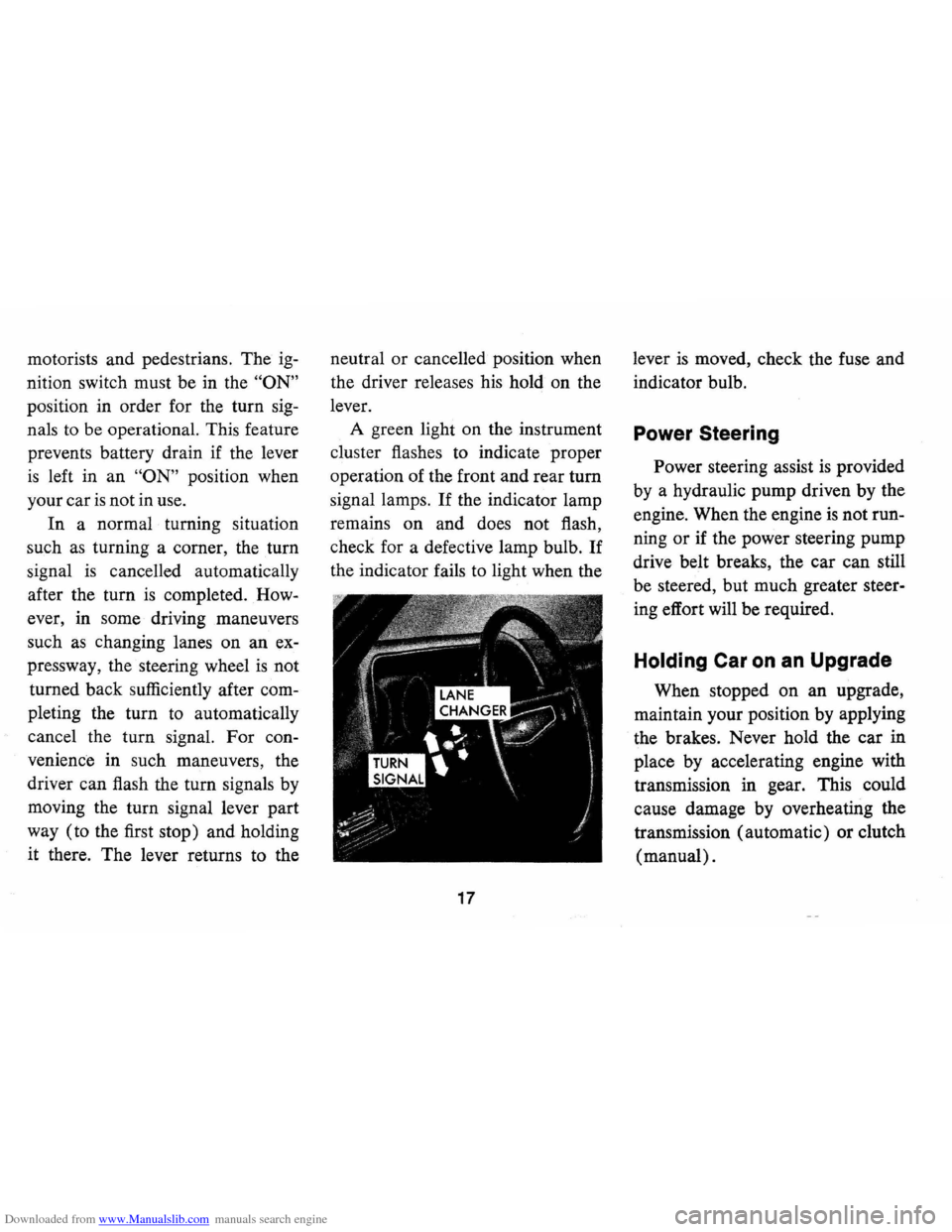
The turn signal lever is located
on the left side of the steering
col
umn immediately under the steer
ing wheel. The lever is moved up
ward to signal a right turn and '
downward to signal a left turn.
Lamps on the front and rear of the
car transmit this signal to other
Page 20 of 88

Downloaded from www.Manualslib.com manuals search engine motorists and pedestrians. The ig
nition switch must be in the "ON"
position in order for the turn sig
nals to be operational. This feature
prevents battery drain if the lever
is left in an "ON" position when
your car
is not in use.
In a normal turning situation
such
as turning a corner, the turn
signal is cancelled automatically
after the turn
is completed. How
ever, in some driving maneuvers
such
as changing lanes on an ex
pressway, the steering wheel
is not
turned back sufficiently after com
pleting the turn to automatically
cancel the turn signal. For con
venience in such maneuvers, the
driver can flash the turn signals by
moving the turn signal lever part
way (to the first stop) and holding
it there. The lever returns to the neutral
or cancelled position when
the driver releases his hold on the
lever.
A green light on the instrument
cluster flashes to indicate proper
operation of the front and rear
tum
signal lamps. If the indicator lamp
remains on and does not flash,
check for a defective lamp bulb.
If
the indicator fails to light when the
17
lever is moved, check the fuse and
indicator bulb.
Power Steering
Power steering assist is provided
by a hydraulic pump driven by the
engine. When the engine
is not run
ning
or if the power steering pump
drive belt breaks, the car can still
be steered, but much greater steer
ing effort will be required.
Holding Car on an Upgrade
When stopped on an upgrade,
maintain your position by applying
the brakes. Never hold the car in
place by accelerating engine with
transmission in gear. This could
cause damage by overheating the
transmission (automatic) or clutch
(manual).
Page 21 of 88

Downloaded from www.Manualslib.com manuals search engine Parking Your Car
Always engage the parking brake
.and place the automatic transmis
sion selector lever in
"Park" posi
tion when leaving your car unat
tended. Also with automatic trans
missions, never park for prolonged
periods with engine idling and
transmission in gear, especially if
your car
is equipped with air con
ditioning. This practice
is detri
mental to the transmission, due to
overheating.
Tilt Steering Wheel
The optional tilt steering wheel
can be tilted up above normal posi
tion to provide additional room for
entrance and exit
as well as selected
driving positions below normal
height. This permits individual
se
lection of the most natural position
for all driving conditions.
On long
trips the steering wheel position can
be changed
to minimize tension and
fatigue.
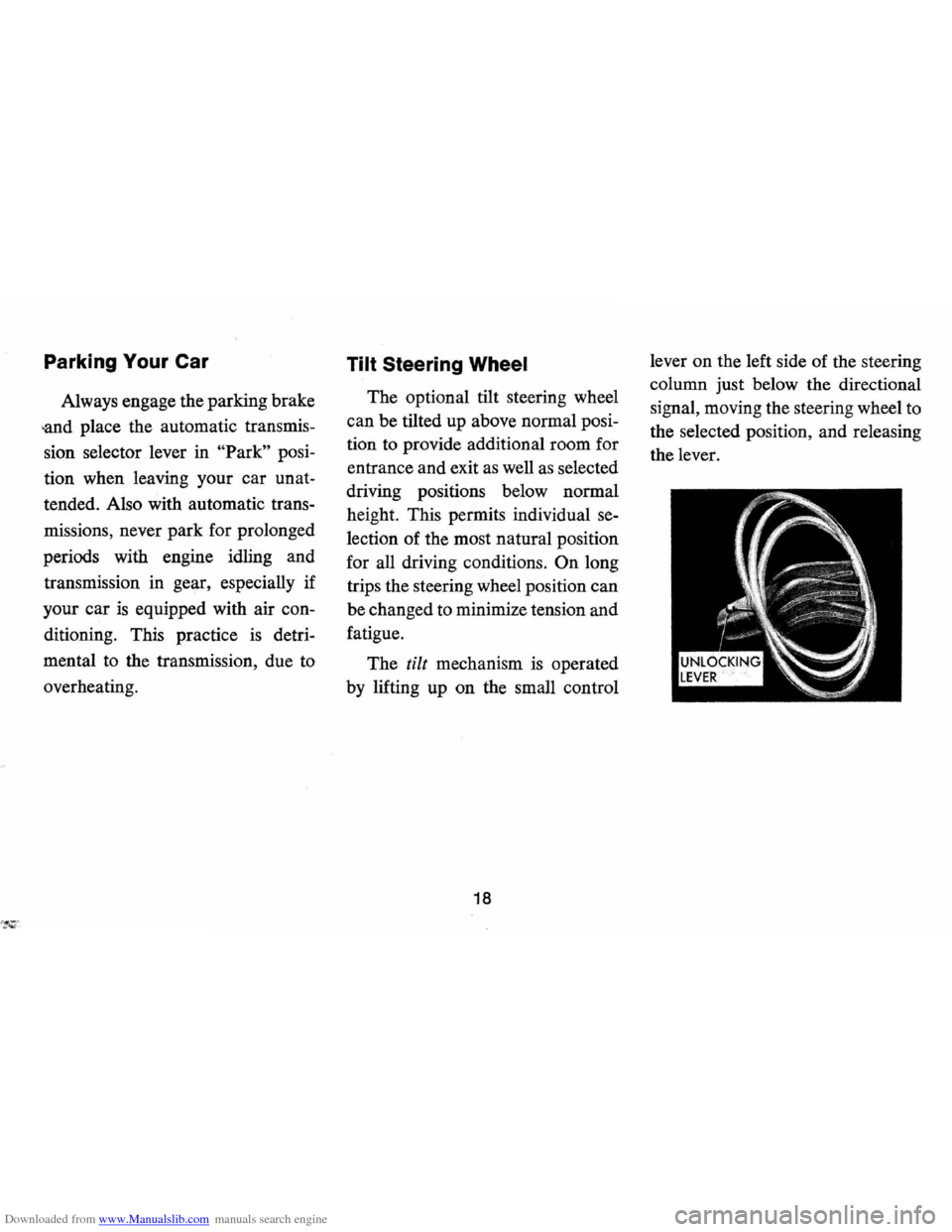
The
tilt mechanism is operated
by lifting up on the small control
18
lever on the left side of the steering
column just below the directional
signal, moving the steering wheel
to
the selected position, and releasing
the lever.
Page 24 of 88

Downloaded from www.Manualslib.com manuals search engine Generator Indicator Light
This light provides a quick check
on the generating system of your
car. The red light will go on when
the ignition key
is in the "on" posi
tion, but before the engine is
started. After the engine starts, the
light should go out and remain out.
If the light remains on when engine
is running, have your Authorized
Chevrolet Dealer locate and correct
the trouble
as soon as possible.
Engine Temperature
Indicator Light
This indicator light is provided
in the instrument cluster to quickly
warn of an overheated engine. With
the ignition
switGh in the START
position, the red TEMP indicator
will light to let you know that it
is
operating properly.
When the engine
is started, the
red light will go out immediately.
It will light up at no other time
unless for some reason the engine
reaches a dangerously high
oper
ating temperature. If the red light
should come on, the engine must be
stopped until the cause of the
over
heating is corrected. Glance at in
strument cluster frequently as you
drive to see if this light
is on.
Brake System Warning
Light
The service brake system is de
signed so that half of the brake sys
tem will provide some braking ac
tion in the event of a hydraulic leak
in the other half of the system.
When the brake apply system
is not
operating properly, a warning light
located at lower left of instrument
cluster (speedometer face) will
glow continuously when the
igni
tion is on after the brakes have been
firmly applied.
On cars equipped
with drum brakes, the light will go
21
out when foot is removed from
brake pedal.
• As a check on bulb condition the
light should glow with the
park
ing brake applied and the igni
tion on. (Light is also a reminder
to release parking brake.)
• Have system repaired if light
does not come on during check.
• This warning light is nota sub
stitute for the visual check of
brake fluid level required
as part
of normal maintenance.
If the light glows red:
• The parking brake is not fully re
leased or,
• The service brake system is par
tially inoperative.
What to do:
1. Check that the parking brake is
released.
2. Pull off the road and stop, care
fully-remembering that:
Page 29 of 88

Downloaded from www.Manualslib.com manuals search engine vehicle, to clear the intake ducts
of snow.
• Keep all windows and vents
closed to reduce dust, road and
wind noise and uncomfortable
drafts.
• For most satisfactory heater op
eration and air circulation, oper
ate fan on low or medium speeds
for normal operation and high
speed for quick warm-up and
during extremely low tempera
tures.
• For adequate rear seat heating,
the area beneath the front seat
must not be blocked by carpet
ing, rags, paper
or other mate
rial and fan should operate on
high blower.
• For additional summer ventila
tion move the
AIR lever to mid
position and the
DEFROSTER
lever to DE-ICE. If greater air
flow is desired, move the FAN
lever down to operate the three-
Rear Window Defroster
To insure clear vision through
the rear window during inclement
weather, the Rear Window De
froster has become established
as a
popular accessory. This unit draws in
air from the passenger compart
ment and directs it against the back
window to remove frost or mois
ture. Its blower has a two-speed
control switch on the instrument
panel.
Four Season Air Conditioning System
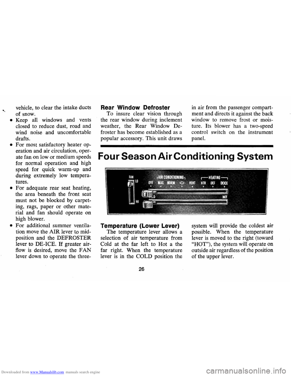
Temperature (Lower Lever)
The temperature lever allows a
selection of air temperature from
Cold at the far left to Hot a the
far right. When the temperature
lever
is in the COLD position the
26
system will provide the coldest air
possible . When the temperature
lever
is moved to the right (toward
"HOT"), the system will operate on
outside air regardless of the position
of the upper lever.
Page 30 of 88

Downloaded from www.Manualslib.com manuals search engine "
Selector (Upper Lever)
This lever provides a selection of
systems available to handle various
heating and cooling requirements
throughout the year. The positions
of the Selector lever are separated
into four (4) major operational
groups
"Off", IIAir Conditioning",
IIVent" and IIHeating". The "Air
Conditioning" and IIHeating"
groups have several positions which
improve the effectiveness of
the
system for various demands.
Fan
The fan lever has four (4) posi
tions from Lo at the top to High at
the bottom. Blower speed
is auto
matically maintained when the
ignition switch
is in the "ON" posi
tion, regardless of the position of
the selector lever. The blower re
mains
ON with the Selector lever
in the
OFF position and the igni
tion switch
ON in order to purge moisture
from the evaporator core
and distributor ducts, thereby help
ing to prevent inadvertent flash
fogging of the windows when the
system
is turned on.
Selector Lever Operation
uOFF" -Shuts the entire system off
but blower automatically remains
operative.
uMAX"-Air from the passenger
compartment is recirculated
through the system and discharged
from the upper outlets when the
temperature lever
is in "Max." cold.
(If the liTem perature" lever is
moved warmer, the system will
automatically
go on outside air.)
The
IIMax." position is used when
maximum cooling
is required under
conditions of high temperature and
humidity.
uNORMAL" -Outside air is passed
through the system and discharged
through the
Ale outlets. This posi-
27
tion is recommended for most air
conditioning situations because of
reduced blower noise and reduction
of cigarette smoke within the
ve
hicle.
uBI-LEVEL"-Outside air is passed
through the system and discharged
from both the upper and lower out
lets. This position
is recommended
for sunny cooler weather where
warm air
is required on the feet
with cooler air above to provide
comfortable breath level. Temper
ature may be adjusted
as desired.
(<> BI-Level position)
NOTE: This position will clear
fogged windows rapidly due to the
dehumidifying effect of the cooling
coils when the outside temperature
is above 30°F.
UVENT" -Air flow and tempera
ture control are the same
as "BI
Level"
except that the compressor
Page 64 of 88

Downloaded from www.Manualslib.com manuals search engine • coolant meeting GM Specification
1899 M should be used.
NOTE: Alcohol or methanol base
coolants or plain water are not rec
ommended for your Camaro at
any time.
Radiator Pressure Cap
The radiator cap, a 15 lb. pres
sure type, must be installed tightly,
otherwise coolant may be lost and
damage to engine may result from
overheating.
Radiator pressure
caps should be checked periodi
cally for proper operation.
If re
placement
is required specify AC.
Thermostat
The cooling system is protected
and controlled by a thermostat in-stalled
in the engine coolant outlet
to maintain a satisfactory operat
ing temperature of the engine. This
thermostat
is designed for continu
ous use through both winter and
summer and need not be changed
seasonally. When replacement
is
necessary, specify United Delco
parts.
Tires
The factory installed tires on
your car are selected to provide the
best all around tire performance
for all normal operation. When in
lated
as recommended in the tire
inflation placard affixed to the left
door of your vehicle, they have the
load carrying capacity to operate
satisfactorily at all loads up to and
including the full rated load speci-
61
fied in that table at all normal high
way speeds. In addition, for those
owners who prefer the utmost in
comfort, optional tire inflation
pressures may be used when loads
of four passengers or less are
carried.
For the added convenience of
owners, many Chevrolet dealers
are equipped to handle tire war
rantyadjustments on certain makes
of tires provided on 1971 Chevro
let cars.
TIRE TRACTION
A decrease in driving, corner
ing, and braking traction occurs
when water, snow, ice, gravel, or
other material
is on the road sur
face. Driving practices and car
speed should be adjusted to the
road conditions.
Page 74 of 88

Downloaded from www.Manualslib.com manuals search engine a bobby pin) between the rubber
cup at the end of the spark plug
wire
and the tubular metal con
nector inside of it. If the spark plug wire is wet or oily, wipe it
dry. Wrap a dry handkerchief or facial tissue, folded several thick·
nesses, around the wire at least
three inches back from the end
and grasp the wire at this point.
Hold the bare wire about 1f4 inch
from the
bare tip of the spark
plug from which you removed the Checking Spark
wire. When the engine is "turned over" a spark should jump across
the 1f4 inch space, indicating ample current supply. If no spark
jumps, the difficulty is probably caused by a defective ignition part
and should be corrected by. your Authorized Chevrolet Dealer.
COOLING SYSTEM
When the car will run but evidences serious overheating on the temperature gauge in the instrument panel, there are several items
which may be checked.
(L) Engine overheating will occur when the OIL LEVEL falls dangerously low. Check the oil level as a matter of course.
(M) Low COOLANT LEVEL will, of course, cause engine over
heating. Determine the cause of the low coolant level and have
it corrected if necessary.
(N) Check the RADIATOR CORE. Clean it if it is plugged with
bugs, leaves or other foreign material.
71
(0) Condition of the FAN BELT is very important, not only for engine cooling but also for proper
generator operation. Check the
condition of the belt. Replace it if it is worn or frayed. Loosen the generator toward the engine to remove and replace the belt. Tighten the belt, whether new or old, by loosening the generator bolts, prying with a bar on the generator until the belt is ten
sioned properly, then retighten
the
generator bolts.
(P) Another cause of engine overheating may be an inoperative COOLING SYSTEM THERMOSTAT. If the thermostat should fail in the closed position, it will not
permit coolant to circulate through
the system.
In such an emergency the thermostat may be removed
but should be replaced with a properly functioning thermostat as soon as possible.
Fan Belt Tension
Thermostat
Installation