1969 FORD MUSTANG clutch
[x] Cancel search: clutchPage 335 of 413

07-02-27
C4 Automatic Transmission
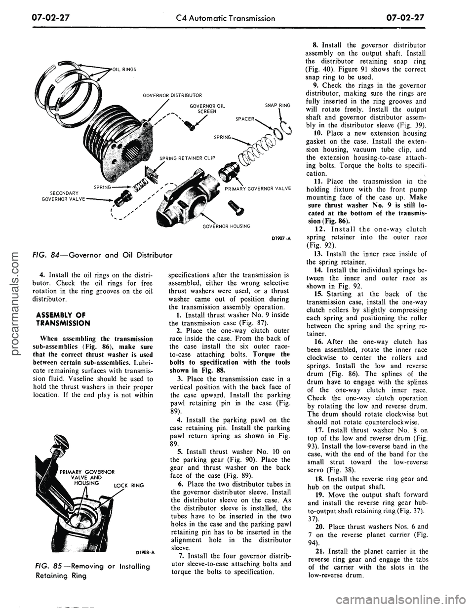
07-02-27
'OIL RINGS
SNAP RING
SECONDARY
GOVERNOR VALVE
1 v s
GOVERNOR HOUSING
D1907-A
FIG. 84—Governor and Oil Distributor
4.
Install the oil rings on the distri-
butor. Check the oil rings for free
rotation in the ring grooves on the oil
distributor.
ASSEMBLY OF
TRANSMISSION
When assembling the transmission
sub-assemblies (Fig. 86), make sure
that the correct thrust washer is used
between certain sub-assemblies. Lubri-
cate remaining surfaces with transmis-
sion fluid. Vaseline should be used to
hold the thrust washers in their proper
location. If the end play is not within
PRIMARY GOVERNOR
VALVE AND
LOCK RING
D1908-A
FIG. 85—Removing or Installing
Retaining Ring
specifications after the transmission is
assembled, either the wrong selective
thrust washers were used, or a thrust
washer came out of position during
the transmission assembly operation.
1.
Install thrust washer No. 9 inside
the transmission case (Fig. 87).
2.
Place the one-way clutch outer
race inside the case. From the back of
the case install the six outer race-
to-case attaching bolts. Torque the
bolts to specification with the tools
shown in Fig. 88.
3.
Place the transmission case in a
vertical position with the back face of
the case upward. Install the parking
pawl retaining pin in the case (Fig.
89).
4.
Install the parking pawl on the
case retaining pin. Install the parking
pawl return spring as shown in Fig.
89.
5.
Install thrust washer No. 10 on
the parking gear (Fig. 90). Place the
gear and thrust washer on the back
face of the case (Fig. 89).
6. Place the two distributor tubes in
the governor distributor sleeve. Install
the distributor sleeve on the case. As
the distributor sleeve is installed, the
tubes have to be inserted in the two
holes in the case and the parking pawl
retaining pin has to be inserted in the
alignment hole in the distributor
sleeve.
7.
Install the four governor distrib-
utor sleeve-to-case attaching bolts and
torque the bolts to specification.
8. Install the governor distributor
assembly on the output shaft. Install
the distributor retaining snap ring
(Fig. 40). Figure 91 shows the correct
snap ring to be used.
9. Check the rings in the governor
distributor, making sure the rings are
fully inserted in the ring grooves and
will rotate freely. Install the output
shaft and governor distributor assem-
bly in the distributor sleeve (Fig. 39).
10.
Place a new extension housing
gasket on the case. Install the exten-
sion housing, vacuum tube clip, and
the extension housing-to-case attach-
ing bolts. Torque the bolts to specifi-
cation.
11.
Place the transmission in the
holding fixture with the front pump
mounting face of the case up. Make
sure thrust washer No. 9 is still lo-
cated at the bottom of the transmis-
sion (Fig. 86).
12.
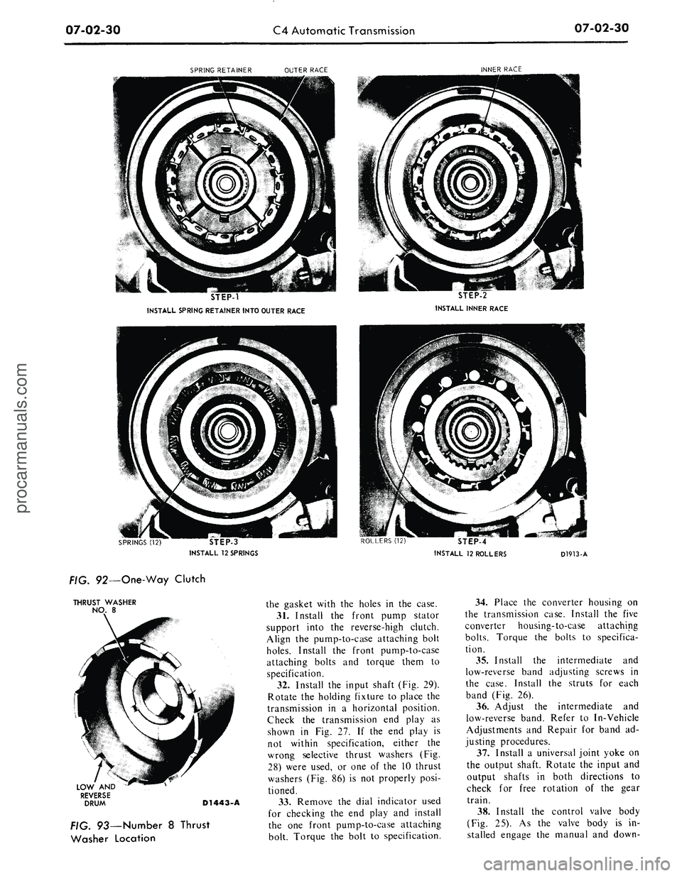
Install the one-wa> clutch
spring retainer into the oui:er race
(Fig. 92).
13.
Install the inner race inside of
the spring retainer.
14.
Install the individual springs be-
tween the inner and outer race as
shown in Fig. 92.
15.
Starting at the back of the
transmission case, install the one-way
clutch rollers by slightly compressing
each spring and positioning the roller
between the spring and the spring re-
tainer.
16.
After the one-way clutch has
been assembled, rotate the inner race
clockwise to center the rollers and
springs. Install the low and reverse
drum (Fig. 86). The splines of the
drum have to engage with the splines
of the one-way clutch inner race.
Check the one-way clutch operation
by rotating the low and reverse drum.
The drum should rotate clockwise but
should not rotate counterclockwise.
17.
Install thrust washer No. 8 on
top of the low and reverse drum (Fig.
93).
Install the low-reverse band in the
case,
with the end of the band for the
small strut toward the low-reverse
servo (Fig. 38).
18.
Install the reverse ring gear and
hub on the output shaft.
19.
Move the output shaft forward
and install the reverse ring gear hub-
to-output shaft retaining ring (Fig. 37).
37).
20.
Place thrust washers Nos. 6 and
7 on the reverse planet carrier (Fig.
94).
21.
Install the planet carrier in the
reverse ring gear and engage the tabs
of the carrier with the slots in the
low-reverse drum.procarmanuals.com
Page 336 of 413

07-02-28
C4
Automatic Transmission
07-02-28
y
Q
!
17
3*1
-
"
-N
1.
2.
3.
4.
5.
6.
7.
8.
9.
10.
11.
CONVERTER
INPUT SHAFT
CONVERTER HOUSING
FRONT PUMP
THRUST WASHER
NO. 1
THRUST WASHER
NO. 2
FRONT PUMP GASKET
INTERMEDIATE BAND
BAND STRUTS
REVERSE
AND
HIGH
CLUTCH DRUM
FORWARD CLUTCH
AND
CYLINDER
12.
13.
14.
15.
16.
17.
18.
19.
20.
THRUST WASHER
NO. 3
FORWARD CLUTCH
HUB
AND RING GEAR
THRUST WASHER
NO. 4
FRONT PLANET CARRIER
INPUT SHELL,
SUN
GEAR
AND THRUST WASHER
NO.
THRUST WASHER
NO. 6
REVERSE PLANET CARRIER
THRUST WASHER
NO. 7
SNAP RING
21.
22.
23.
24.
25.
26.
27.
28.
29.
REVERSEH*ING GEAR
AND
HUB
LOW
AND
REVERSE BAND
BAND STRUTS
THRUST WASHER
NO. 8
LOW
AND
REVERSE DRUM
ONE-WAY CLUTCH
INNER RACE
ROLLER
(12) AND
SPRING
(12)
SPRING
AND
ROLLER CAGE
ONE-WAY CLUTCH OUTER
RACE
30.
31.
32.
33.
34.
35.
36.
37.
38.
39.
40.
THRUST WASHER NO. 9
CASE
THRUST WASHER NO. 10
PARKING GEAR
GOVERNOR DISTRIBUTOR
SLEEVE
SNAP RING
GOVERNOR VALVES
&
DISTRIBUTOR
OUTPUT SHAFT
EXTENSION HOUSING
AND
GASKET
CONTROL VALVE BODY
OIL
PAN AND
GASKET
D 1378-D
FIG.
86—Transmission Sub-Assembliesprocarmanuals.com
Page 337 of 413

07-02-29
C4 Automatic Transmission
07-02-29
THRUST WASHER
NO. 9
PARKING GEAR
BOTTOM
OF CASE
FIG. 87—Number
9
Thrust
Washer Location
Tool-T65P-7B456-B
D1910-A
FIG. 88—Installing One-Way
Clutch Outer Race Attaching Bolts
REJURN
S
PAWL
PARKING
GEAR RETAINING
PIN
D1440-A
FIG. 89— Parking Pawl
and
Gear
THRUST
WASHER
NO.
10
D1911-A
FIG. 90—Number
10
Thrust
Washer Location
22.
On the
bench, install
the for-
ward clutch
in the
reverse-high clutch
by rotating
the
units
to
mesh
the
reverse-high clutch plates with
the
splines
of
the
forward clutch
(Fig. 95).
23.
Using
the end
play check read-
ing that
was
obtained during
the
transmission disassembly
to
determine
which
No.
2
steel backed thrustwasher
is required, proceed
as
follows:
a.
Position
the
stator support verti-
cally
on the
work bench
and
install
the correct
No. 2
thrustwasher
to
bring
the end
play within specifica-
tions.
RETAINS REVERSE RING GEAR
AND
HUB
TO
OUTPUT SHAFT
RETAINS GOVERNOR DISTRIBUTOR
TOOUTPUTSHAFT
D1549-A
FIG. 91—Governor
and
Reverse
Ring Hub-Retaining Snap Ring
Identification
b.
Install
the
reverse-high clutch
and
the
forward clutch
on the
stator
support.
c. Invert
the
complete unit making
sure that
the
intermediate brake drum
bushing
is
seated
on the
forward
clutch mating surface.
d.
Select
the
thickest fiber washer
(No.
1)
that
can be
inserted between
the stator support
and the
intermedi-
ate brake drum thrust surfaces
and
still maintain
a
slight clearance.
Do
not select
a
washer that must
be
forced between
the
stator support
and
intermediate brake drum.
e. Remove
the
intermediate brake
drum
and
forward clutch unit from
the stator support.
f.
Install
the
selected
Nos.
1 and 2
thrustwashers
on the
front pump
sta-
tor support
(Fig.
28)
using enough
vaseline
to
hold
the
thrust washers
in
position during
the
front pump instal-
lation.
24.
Install thrust washer
No.
3 on
the forward clutch
(Fig. 96).
25.
Install
the
forward clutch
hub
and ring
in the
forward clutch
by ro-
tating
the
units
to
mesh
the
forward
clutch plates with
the
splines
on the
forward clutch
hub (Fig. 97).
26.
Install thrust washer
No.
4 on
the front planet carrier
(Fig. 98).
In-
stall
the
front planet carrier into
the
forward clutch
hub and
ring gear.
Check
the
forward thrust bearing race
inside
the
planet carrier
for
proper
location against
the
thrust bearing.
Make sure
the
race
is
centered
for
alignment with
the sun
gear
on the
input shell
(Fig. 99).
27.
Install
the
input shell
and sun
gear
on
the
gear train
(Fig. 100). Ro-
tate
the
input shell
to
engage
the
drive
lugs
of the
reverse-high clutch.
If the
drive lugs will
not
engage,
the
outer
race inside
the
forward planet carrier
is
not
centered
to
engage
the end of
the
sun
gear inside
the
input shell.
Center
the
thrust bearing race
and
in-
stall
the
input shell.
28.
Hold
the
gear train together
and install
the
forward part
of the
gear train assembly
in the
case
(Fig.
33).
The input shell
sun
gear must mesh
with
the
reverse pinion gears.
The
front planet carrier internal splines
must mesh with
the
splines
on the out-
put shaft.
29.
A
new
band should
be
soaked
in transmission fluid
for
fifteen
min-
utes before
it is
installed. Install
the
intermediate band through
the
front
of
the case
(Fig. 31).
30.
Install
a
new
front pump gasket
on
the
case. Line
up
the
bolt holes
inprocarmanuals.com
Page 338 of 413

07-02-30
C4 Automatic Transmission
07-02-30
SPRING RETAINER
OUTER RACE
INNER RACE
STEP-1
INSTALL SPRING RETAINER INTO OUTER RACE
STEP-2
INSTALL INNER RACE
STEP-3
INSTALL
12
SPRINGS
ROLLERS
(12)
STEP-4
INSTALL
12
ROLLERS
D1913-A
FIG. 92—One-Way Clutch
THRUST
WASHER
NO.
8
LOW
AND
REVERSE
DRUM
D1443-A
FIG. 93—Number
8
Thrust
Washer Location
the gasket with
the
holes
in the
case.
31.
Install
the
front pump stator
support into
the
reverse-high clutch.
Align
the
pump-to-case attaching bolt
holes.
Install
the
front pump-to-case
attaching bolts
and
torque them
to
specification.
32.
Install
the
input shaft
(Fig.
29).
Rotate
the
holding fixture
to
place
the
transmission
in a
horizontal position.
Check
the
transmission
end
play
as
shown
in Fig. 27. If the end
play
is
not within specification, either
the
wrong selective thrust washers
(Fig.
28) were used,
or one of the 10
thrust
washers
(Fig.
86) is not
properly posi-
tioned.
33.
Remove
the
dial indicator used
for checking
the end
play
and
install
the
one
front pump-to-case attaching
bolt. Torque
the
bolt
to
specification.
34.
Place
the
converter housing
on
the transmission case. Install
the
five
converter housing-to-case attaching
bolts.
Torque
the
bolts
to
specifica-
tion.
35.
Install
the
intermediate
and
low-reverse band adjusting screws
in
the case. Install
the
struts
for
each
band
(Fig.
26).
36.
Adjust
the
intermediate
and
low-reverse band. Refer
to
In-Vehicle
Adjustments
and
Repair
for
band
ad-
justing procedures.
37.
Install
a
universal joint yoke
on
the output shaft. Rotate
the
input
and
output shafts
in
both directions
to
check
for
free rotation
of the
gear
train.
38.
Install
the
control valve body
(Fig.
25). As the
valve body
is in-
stalled engage
the
manual
and
down-procarmanuals.com
Page 339 of 413

07-02-31
C4 Automatic Transmission
07-02-31
REVERSE PLANET CARRIER
THRUST WASHER NO. 7
THRUST WASHER NO. 6
FIG. 94 —Number 6 and 7 Thrust Washer Location
D1444-A
shift valves with the inner control le-
vers.
Torque the control valve body-
to-case attaching bolts to specifica-
tion.
39.
Place a new pan gasket on the
case and install the pan and pan-
to-case attaching bolts. Torque the at-
taching bolts to specification.
40.
Remove the transmission from
FORWARD CLUTCH HUB
AND RING GEAR
FORWARD
CLUTCH
REVERSE-HIGH
CLUTCH
FORWARD
CLUTCH
D1914-A
FIG. 95—Installing Clutch Units
THRUST WASHER NO. 3 FORWARD
CLUTCH CYLINDER
REVERSE-HIGH CLUTCH
D1446-A
D1915-A
FIG. 96—Number 3 Thrust
Washer Location
FIG. 97—Installing Forward
Clutch Hub and Ring Gear
THRUS
WASHER
NO.
4
D1916-A
FIG. 98—Number 4 Thrust
Washer Location
the holding fixture. Install the two ex-
tension housing-to-case attaching
bolts.
Torque the bolts to specifica-
tion.
41
valve
Install the primary throttle
in the transmission case (Fig.
23).
42.
Install the vacuum unit, gasket,
and control rod in the case. Using the
tools shown in Fig. 101, torque the
vacuum unit to 15-23 ft-lbs.
FRONT PLANET
CARRIER
FORWARD CLUTCH
HUB AND
GEAR
FORWARD
CLUTCH
REVERSE-HIGH CLUTCH
FIG. 99—Installing Front
Planet Carrier
D1917-Aprocarmanuals.com
Page 340 of 413

07-02-32
C4 Automatic Transmission
07-02-32
INPUT SHELL
SUN GEAR
DRIVE
LUG
ENGAGEMENT
REVERSE-HIGH
CLUTCH
D1918-A
FIG. TOO—Installing Input Shell
43.
Make sure
the
input shaft
is
properly installed
in the
front pump
stator support
and
gear train. Install
the converter
in the
front pump
and
the
the
converter housing.
Tool-FCO-24
Reworked
D1919-A
FIG. 707—Installing Vacuum Unitprocarmanuals.com
Page 341 of 413

07-03-01
FMX Transmission
07-03-01
PART
7-3 FMX
Transmission
SELECTOR
TRANSMISSION ENGINE LEVER
MODEL MODEL LOCATION
PHB-A 390-2V Column
PHB-C 351-2V Column
PHB-D 351-2V Console
PHB-E 351-2V Console
PHB-F 351-4V Column
PHB-G 351-4V Console
PHB-H 351-4V Console
PHD-A 240-1V Column
PHD-B 302-2V Column
MODEL APPLICATION
All
Models
Ford
X
X
X
Mercury
Meteor
X
X
X
Cougar
X
X
Fairlane
X
X
X
X
Falcon
Montego
X
X
X
X
Mustang
X
X
Lincoln-
Continental
Thunderbird
Continental-
Mark III
COMPONENT INDEX
ASSEMBLY
OF
TRANSMISSION
End Play Check
BAND ADJUSTMENTS
Front Band
Rear Band (Ford
and
Meteor)
Rear Band (Fairlane, Montego, Mustang
and
Cougar)
External Adjustment
Internal Adjustment
CENTER SUPPORT, ONE-WAY CLUTCH
AND PINION CARRIER
Assembly
Center Support With Chamfered Edge
Center Support
not
Chamfered
Inspection
CONTROL VALVE BODY
Assembly
Disassembly
and
Overhaul
Inspection
Removal
and
Installation
DESCRIPTION
DISASSEMBLY
AND
OVERHAUL
OF
TRANSMISSION
End Play Check
DOWNSHIFT LINKAGE
Adjustment
Parts Repair
or
Replacement
EXTENSION HOUSING
Assembly
Inspection
EXTENSION HOUSING BUSHING
Page
03-26
03-08
03-09
03-09
03-10
03-10
03-10
03-26
03-26
03-27
03-14
03-28
03-21
03-16
03-11
03-03
03-16
03-16
03-05
03-25
03-28
03-14
COMPONENT INDEX
Removal
and
Installation
EXTENSION HOUSING REAR SEAL
Removal
and
Installation
FLUID FILTER ASSEMBLY
FRONT CLUTCH
Assembly
Disassembly
and
Overhaul
Inspection
FRONT PUMP
Assembly
Disassembly
and
Overhaul
Inspection
FRONT SERVO
Assembly
Disassembly
and
Overhaul
Inspection
Removal
and
Installation
GOVERNOR
Assembly
Disassembly
and
Overhaul
Inspection
Removal
and
Installation
MANUAL LINKAGE
Adjustments
Parts Repair
or
Replacement
NEUTRAL START SWITCH-CONSOLE SHIFT
Adjustment
Removal
and
Installation
(Refer
to
Part 7-1
for
Column Shift
Adjustment
and
Removal
and
Installation
procedures)
1
Page
03-13
03-13
03-29
03-26
03-19
03-15
03-28
03-20
01-15
03-28
03-24
01-16
03-12
03-28
03-24
01-16
03-10
03-05
03-25
03-05
03-07
procarmanuals.com
Page 342 of 413

07-03-02
FMX Transmission
07-03-02
COMPONENT INDEX
OIL PAN
Assembly
Removal and Installation
OUTPUT SHAFT
Assembly
Inspection
OUTPUT SHAFT BUSHING
Disassembly and Overhaul
PARKING PAWL
Removal and Installation
PRESSURE REGULATOR
Assembly
Disassembly and Overhaul
Inspection
Removal and Installation
PRIMARY SUN GEAR SHAFT
Disassembly and Overhaul
Inspection
REAR BRAKE DRUM SUPPORT BUSHING
Disassembly and Overhaul
REAR CLUTCH
Assembly
Disassembly and Overhaul
Inspection
Page
03-29
03-11
03-26
01-11
03-17
03-13
03-28
03-21
01-16
03-12
03-18
01-11
03-17
03-26
03-18
01-15
REAR SERVO
Assembly
Disassembly and Overhaul
Inspection
Removal and Installation
REAR SUPPORT
Assembly
Inspection
REAR SUPPORT BUSHING
Disassembly and Overhaul
SELECTOR LEVER-CONSOLE SHIFT
Removal and Installation
THROTTLE LINKAGE
Adjustment
Parts Repair or Replacement
TRANSMISSION (Complete)
Removal and Installation
TRANSMISSION CASE BUSHING
Parts Repair or Replacement
TRANSMISSION CASE LINKAGE
Parts Repair or Replacement
VACUUM DIAPHRAGM UNIT
Assembly
Adjustment
Checking
Page
03-28
03-24
01-16
03-12
03-28
03-15
03-21
03-08
03-05
03-05
03-14
03-26
03-25
03-29
01-07
01-04
DESCRIPTION
DESCRIPTION
Figure 1 shows the location of the
converter, front pump, clutches,
bands,
gear train and most of the in-
ternal parts used in the FMX Trans-
mission
The identification tag (Fig. 2) on an
FMX transmission is attached under
the oil pan by a pan to case bolt. The
tag includes the model prefix and suf-
fix, assembly part number and the
build date code.
The service identification number
indicates changes to service details
which affect interchangeability when
the transmission model is not
changed. For interpretation of this
number, see the Master Parts Catal-
og-
The tag must be kept with the indi-
vidual transmission it was originally
installed on. If the tag was removed
during disassembly, reinstall it on the
same unit.
The FMX transmission is a three
speed unit capable of providing auto-
matic upshifts and downshifts through
the three forward gear ratios, and also
capable of providing manual selection
of first and second gears.
The transmission consists essentially
of a torque converter, planetary gear
train, two multiple disc clutches and a
hydraulic control system (Fig. 3).
procarmanuals.com