1969 FORD MUSTANG clutch
[x] Cancel search: clutchPage 312 of 413

07-02-04
C4 Automatic Transmission
07-02-04
The transmission consists essentially
of a torque converter, planetary gear
train, two multiple disc clutches, a
one-way clutch and a hydraulic con-
trol system (Fig. 3).
The only adjustments on the trans-
mission proper are the intermediate
and low-reverse bands.
TRANSMISSION
MANUAL LEVER
2 IN-VEHICLE ADJUSTMENTS
AND
REPAIRS
CONTROL LINKAGE ADJUSTMENTS
The transmission control linkage
adjustments should be performed in
the order in which they appear in this
section of the manual.
THROTTLE AND DOWNSHIFT
LINKAGE ADJUSTMENTS
Adjusting the throttle linkage is im-
portant to be certain the throttle and
kickdown systems are properly adjust-
ed. The kickdown system should come
in when the accelerator is pressed
through detent, and not before detent.
Refer to Group 10 for detailed
throttle and downshift linkage adjust-
ment procedures.
MANUAL LINKAGE
ADJUSTMENTS
Column Shift
1.
Place the selector lever in the D
position tight against the D stop.
2.
Loosen the shift rod adjusting
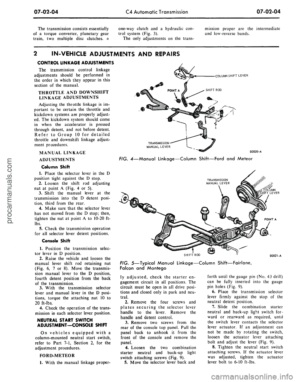
nut at point A (Fig. 4 or 5).
3.
Shift the manual lever at the
transmission into the D detent posi-
tion, third from the rear.
4.
Make sure that the selector lever
has not moved from the D stop; then,
tighten the nut at point A to 10-20 ft-
lbs.
5.
Check the transmission operation
for all selector lever detent positions.
Console Shift
1.
Position the transmission selec-
tor lever in D position.
2.
Raise the vehicle and loosen the
manual lever shift rod retaining nut
(Fig. 6, 7 or 8). Move the transmis-
sion manual lever to the D position,
fourth detent position from the back
of the transmission.
3.
With the transmission selector
lever and manual lever in the D posi-
tions,
torque the attaching nut 10 to
20 ft-lbs.
4.
Check the operation of the trans-
mission in each selector lever position.
NEUTRAL START SWITCH
ADJUSTMENT—CONSOLE SHIFT
On vehicles equipped with a
column-mounted neutral start switch,
refer to Part 7-1, Section 2, for the
adjustment procedures.
FORD-METEOR
1.
With the manual linkage proper-
COLUMN SHIFT LEVER
D2020-A
FIG.
4—Manual
Linkage—Column Shift—Ford
and
Meteor
"COLUMN
SHIFT LEVER
POINT
A
SHIFT
ROD
D2021-A
FIG.
5—Typical
Manual Linkage—Column
Shift—Fairlane,
Falcon
and
Montego
ly adjusted, check the starter en-
gagement circuit in all positions. The
circuit must be open in all drive posi-
tions and closed only in park and neu-
tral.
2.
Remove the four screws and
plates securing the selector lever
handle to the lever. Remove the
handle and detent control.
3.
Remove two screws from the
rear of the console top panel. Pull the
panel back to unhook it from the
front of the console and remove the
panel.
4.
Loosen the two combination
starter neutral and back-up light
switch attaching screws (Fig. 9).
5.
Move the selector lever back and
forth until the gauge pin (No. 43 drill)
can be fully inserted into the gauge
pin holes (Fig. 9).
6. Place the transmission selector
lever firmly against the stop of the
neutral detent position.
7.
Slide the combination starter
neutral and back-up light switch for-
ward or rearward as required, until
the switch lever contacts the selector
lever actuator. If an adjustment can
not be made by rotating the switch,
loosen the actuator lever attaching
bolt and adjust the lever (Fig. 9).
8. Tighten the neutral start switch
attaching screws. If the actuator lever
was adjusted, tighten the actuator
lever bolt to 6-10 ft-lbs.procarmanuals.com
Page 320 of 413

07-02-12
C4 Automatic Transmission
07-02-12
MAJOR REPAIR OPERATIONS
Before removing
any of the sub-
assemblies, thoroughly clean
the out-
side
of the
transmission
to
prevent dirt
from entering
the
mechanical parts.
During
the
repair operations, refer
to
Part 7-1
for
common adjustments
and
repairs
or
cleaning
and
inspection
pro-
cedures.
During
the
transmission disassem-
bly
or
assembly operations,
ten
thrust
washers located between
the sub-
assemblies must
be
removed
and in-
stalled.
It is
important that each
thrust washer
be in the
correct posi-
tion during
the
assembly operation.
To properly locate
and
identify
the
thrust washers,
the
various positions
of
the
thrust washers
are
shown
in the
illustrations
and are
numbered
1
through
10. No. 1 is at the
first thrust
washer located
at the
front pump.
The
last thrust washer,
No. 10, is
located
at
the
parking pawl ring gear.
DISASSEMBLY
OF
TRANSMISSION
1.
Remove
the
converter from
the
transmission front pump
and
convert-
er housing.
2.
Remove
the
transmission vacuum
unit with
the
tool shown
in Fig. 22.
Remove
the
vacuum unit gasket and
the control
rod.
GRIND OFF
SHADED AREA
TO DIMENSION SHOWN L .
SNAP-ON
Tool-FCO-24
(Reworked)
D1380-A
FIG. 22—Removing Vacuum Unit
3.
Remove
the
primary throttle
valve (Fig.
23)
from
the
opening
at the
rear
of the
case.
4.
Remove
the two
extension
housing-to-case bolts shown
in Fig. 24
and mount
the
transmission
in the
holding fixture.
5.
Remove
the
transmission
pan at-
taching bolts,
pan and
gasket.
6. Remove
the
control valve body
attaching bolts (Fig.
25).
Remove
the
control valve body from
the
case.
7.
Loosen
the
intermediate band
adjusting screw
(Fig. 26) and
remove
the intermediate band struts from
the
case.
Loosen
the
low-reverse band
ad-
justing screw
and
remove
the low-
reverse band struts.
TRANSMISSION END
PLAY CHECK
1.
To
keep
the
output shaft
in
alignment during
the end
play check,
install
the
extension housing
oil
seal
replacer tool
or a
front universal
D1861-A
FIG. 23—Removing
or
Installing
Primary Throttle Valve
Tool-T57L-500-A
or 6005-M or 6005-MS
D1862-A
joint yoke in the extension housing.
2.
Remove
one of the
converter
housing-to-case attaching bolts
and
mount
the
dial indicator
as
shown
in
Fig. 27.
3.
The
input shaft
is a
loose part
and
has to be
properly engaged with
the spline
of the
forward clutch
hub
during
the end
play checking proce-
dure.
Move
the
input shaft
and
gear
train toward
the
rear
of the
transmis-
sion case.
V*
- 20 x
V/7 INCH
V*
- 20 x 1
INCH
V*
- 20 x 1
INCH
D1863-A
FIG. 25—Control Valve Body
Attaching Bolts
INTERMEDIATE
BAND STRUTS
INTERMEDIATE BAND
ADJUSTING SCREW
I
LOW-REVERSE BAND
ADJUSTING SCREW
LOW-REVERSE
BAND STRUTS
D
1384-B
FIG.
24—Transmission
Mounted
in Holding Fixture
FIG. 26—Band Adjusting Screws
and Struts—Typicalprocarmanuals.com
Page 322 of 413

07-02-14
C4 Automatic Transmission
07-02-14
FORWARD CLUTCH
FORWARD CLUTCH FRONT PLANET CARRIER INPU^ SHELL
HUB AND
RING GEAR
SUN GEAR
REVERSE-HIGH CLUTCH
THRUST WASHER
NO.
5
FIG. 35—Forward Part of Gear Train Disassembled
D1872-A
taching bolts. Remove the front pump
by inserting a screwdriver behind the
input shell (Fig. 30). Move the input
shell forward until the front pump seal
is above the edge of the case.
Remove the front pump and gasket
from the case. If the selective thrust
washer No. 1 did not come out with
the front pump, remove it from the
top of the reverse-high clutch.
4.
Remove the intermediate and
low-reverse band adjusting screws
from the case. Rotate the intermediate
band to align the band ends with the
clearance hole in the case (Fig. 31).
Remove the intermediate band from
the case.
5.
Using a screwdriver between the
input shell and rear planet carrier
(Fig. 32), lift the input shell upward
and remove the forward part of the
gear train as an assembly (Fig. 33).
6. Place the forward part of the
gear train in the holding fixture shown
in Fig. 34.
7.
From the gear train in the hold-
ing fixture, remove the reverse-high
clutch and drum from the forward
clutch (Fig. 35).
8. If thrust washer No. 2 (Fig. 28)
did not come out with the front pump,
remove the thrust washer from the
forward clutch cylinder. Remove the
forward clutch from the forward
clutch hub and ring gear (Fig. 35).
9. If thrust washer No. 3 (Fig. 35)
did not come out with the forward
clutch, remove the thrust washer from
the forward clutch hub.
10.
Remove the forward clutch hub
and ring gear from the front planet
carrier (Fig. 35).
11.
Remove thrust washer No. 4
and the front planet carrier from the
input shell.
12.
Remove the input shell, sun
gear and thrust washer No. 5 from the
holding fixture.
13.
From inside the transmission
case (Fig. 33) remove thrust washer
No.
6 from the top of the reverse
planet carrier.
14.
Remove the reverse planet car-
rier and thrust washer No. 7 from the
reverse ring gear and hub (Fig. 36).
15.
Move the output shaft forward
and with the tool shown in Fig. 37 re-
move the reverse ring gear hub-
to-output shaft retaining ring.
16.
Remove the reverse ring gear
and hub from the output shaft. Re-
move thrust washer No. 8 from the
low and reverse drum.
17.
Remove the low-reverse band
from the case (Fig. 38).
18.
Remove the low-reverse drum
from the one-way clutch inner race
(Fig. 36).
19.
Remove the one-way clutch
inner race by rotating the race clock-
wise as it is removed.
20.
Remove the 12 one-way clutch
rollers, springs and the spring retainer
from the outer race (Fig. 36). Do not
lose or damage any of the 12 springs
REVERSE PLANET CARRIER
THRUST WASHER NO. 8
THRUST WASHER NO. 9
SPRING RETAINER
INNER RACE
THRUST WASHER NO. 6
LOW AND REVERSE DRUM
ONE-WAY
CLUTCH
SPRINGS (12)
AND ROLLERS (12)
OUTER RACE
D1394-A
FIG. 36—Lower Part of Gear Train Disassembledprocarmanuals.com
Page 323 of 413

07-02-15
C4 Automatic Transmission
07-02-15
GOVERNOR DISTRIBUTOR
REVERSE RING GEAR
HUB RETAINING RING
D 2044-A
FIG.
37—Removing
or
Installing
Reverse
Ring Gear
Hub
Retaining
Ring
I®
LOW-RE'VERSE BAND
D1873-A
FIG.
38—Removing
or
Installing
Low-Reverse
Band
OUTPUT SHAFT
GOVERNOR
DISTRIBUTOR
SLEEVE
D1875-A
FIG.
39—Removing
or
Installing
Output
Shaft
and
Governor
Distributor
LOCK RING
D1876-A
FIG.
40—Removing
or
Installing
Governor
Distributor Snap Ring
or rollers.
The
outer race
of the one-
way clutch cannot
be
removed worn
the case until
the
extension housing,
output shaft
and
governor distributor
sleeve
are
removed.
21.
Remove
the
transmission from
the holding fixture. Position
the
trans-
mission
on the
bench
in a
vertical
po-
sition with
the
extension housing
up.
Remove
the
four extension housing-
to-case attaching bolts. Remove
the
extension housing
and
gasket from
the
case.
22.
Pull outward
on the
output
shaft
and
remove
the
output shaft
and
governor distributor assembly from
the governor distributor sleeve
(Fig.
39).
23.
Remove
the
governor distribu-
tor lock ring from
the
output shaft
(Fig.
40).
Remove
the
governor
dis-
tributor from
the
output shaft.
24.
Remove
the
four distributor
sleeve-to-case attaching bolts. Remove
the distributor sleeve from
the
case.
Do
not
bend
or
distort
the
fluid tubes
as
the
tubes
are
removed from
the
case with
the
distributor sleeve.
25.
Remove
the
parking pawl
re-
turn spring, pawl,
and
pawl retaining
pin from
the
case (Fig.
41).
26.
Remove
the
parking gear
and
thrust washer
No. 10
from
the
case.
27.
Remove
the six
one-way clutch
outer race-to-case attaching bolts with
the tool sh^'vn
in
Fig. 42.
As the
bolts
are removed, hold
the
outer race
lo-
cated inside
the
case
in
position.
Re-
move
the
outer race
and
thrust washer
No.
9
from
the
case (Fig.
36).
Too/-
T65P.7B456-8
D1879-A
FIG.
42—Removing One-Way
Clutch
Outer Race
Attaching
Bolts
PARKING GEAR
i^ffif
THRUST WASHER NO. 10 ^*t^
$
D1399-A
FIG.
41—Parking
Pawl,
Return Spring Retaining
Pin and
Gearprocarmanuals.com
Page 330 of 413

07-02-22
C4 Automatic Transmission
07-02-22
Handle
Fress
Ram
ress
Ram
Hand!
Tool
-
T66L-7003-S9
Too/
-
T66L-7003-B5
INSTALL BUSHING WITH GROOVE
JAND SLOT
IN
THIS POSITION
REMOVAL
INSTALLATION
FIG. 61—Replacing Front Pump Housing Bushing
D 1732-C
mark
has to be
positioned downward
against
the
face
of the
pump housing.
3.
Press
new
bushings into
the sta-
tor support with
the
tool shown
in
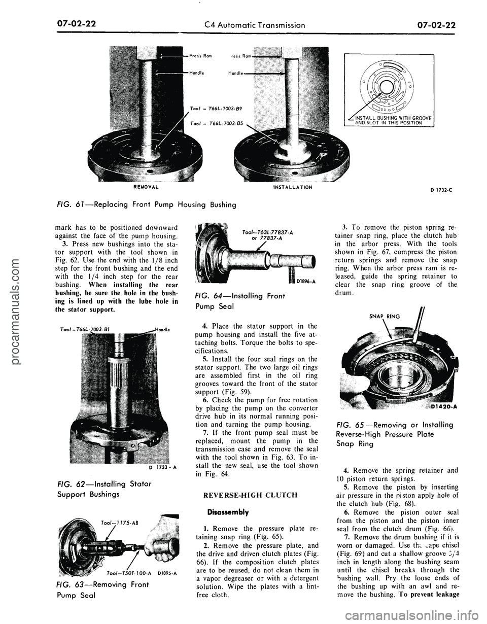
Fig. 62.
Use the end
with
the 1/8
inch
step
for the
front bushing
and the end
with
the 1/4
inch step
for the
rear
bushing. When installing
the
rear
bushing,
be
sure
the
hole
in the
bush-
ing
is
lined
up
with
the
lube hole
in
the stator support.
T00I-T66L
Toot-T63L-77837-A
or 77837-A
D 1733
-
A
FIG. 62—Installing Stator
Support Bushings
Tool-T50T-100-A D1895-A
FIG. 63—Removing Front
Pump Seal
D1896-A
FIG. 64—Installing Front
Pump Seal
4.
Place
the
stator support
in the
pump housing
and
install
the
five
at-
taching bolts. Torque
the
bolts
to
spe-
cifications.
5.
Install
the
four seal rings
on the
stator support.
The two
large
oil
rings
are assembled first
in the oil
ring
grooves toward
the
front
of the
stator
support (Fig.
59).
6. Check
the
pump
for
free rotation
by placing
the
pump
on the
converter
drive
hub in its
normal running posi-
tion
and
turning
the
pump housing.
7.
If the
front pump seal must
be
replaced, mount
the
pump
in the
transmission case
and
remove
the
seal
with
the
tool shown
in Fig.
63.
To in-
stall
the new
seal,
use the
tool shown
in
Fig. 64.
REVERSE-HIGH CLUTCH
Disassembly
1.
Remove
the
pressure plate
re-
taining snap ring (Fig.
65).
2.
Remove
the
pressure plate,
and
the drive
and
driven clutch plates (Fig.
66).
If the
composition clutch plates
are
to be
reused,
do not
clean them
in
a vapor degreaser
or
with
a
detergent
solution. Wipe
the
plates with
a
lint-
free cloth.
3.
To
remove
the
piston spring
re-
tainer snap ring, place
the
clutch
hub
in
the
arbor press. With
the
tools
shown
in Fig. 67,
compress
the
piston
return springs
and
remove
the
snap
ring. When
the
arbor press
ram is re-
leased, guide
the
spring retainer
to
clear
the
snap ring groove
of the
drum.
SNAP RING
D1420-A
FIG. 65—Removing
or
Installing
Reverse-High Pressure Plate
Snap Ring
4.
Remove
the
spring retainer
and
10 piston return springs.
5.
Remove
the
piston
by
inserting
air pressure
in the
piston apply hole
of
the clutch
hub
(Fig.
68).
6. Remove
the
piston outer seal
from
the
piston
and the
piston inner
seal from
the
clutch drum (Fig.
66).
7.
Remove
the
drum bushing
if it is
worn
or
damaged.
Use
thw ^ape chisel
(Fig. 69)
and cut a
shallow groove
3/4
inch
in
length along
the
bushing seam
until
the
chisel breaks through
the
bushing wall.
Pry the
loose ends
of
the bushing
up
with
an awl and re-
move
the
bushing.
To
prevent leakageprocarmanuals.com
Page 331 of 413

07-02-23
C4 Automatic Transmission
07-02-23
SNAP RING
DRIVE PLATES
REVERSE
AND
HIGH
CLUTCH CYLINDER
SPRING RETAINER
PISTON
PISTON SEALS
PISTON
RETURN SPRING
(10) SNAP RING
DRIVEN PLATES
PRESSURE PLATE
D1897-A
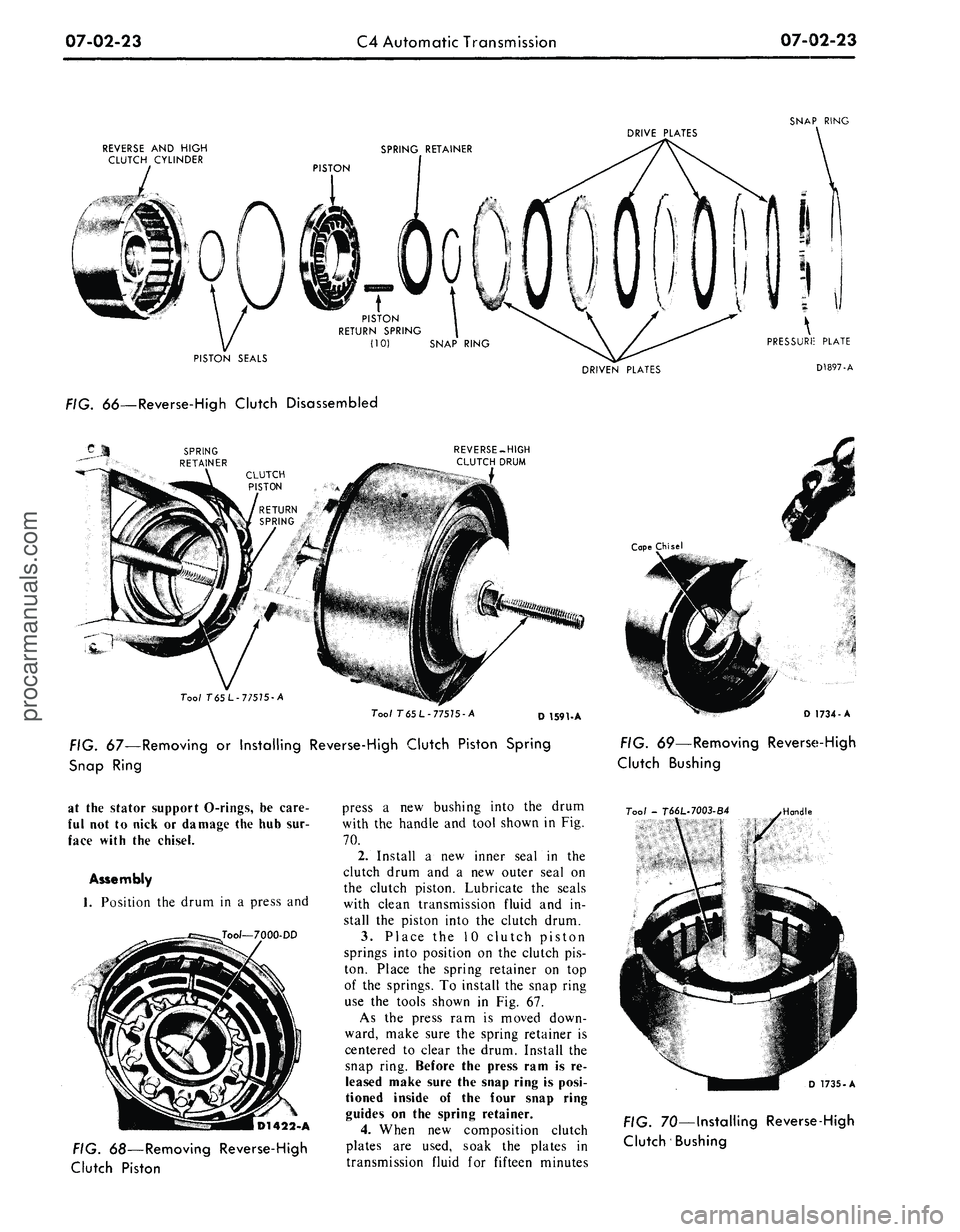
. oo—Reverse-High Clutch Disassembled
REVERSE-HIGH
CLUTCH DRUM
Tool T65L-77575-A
Tool T
65
L- 77575 -A
D 1591-A
FIG. 67—Removing
or
Installing Reverse-High Clutch Piston Spring
Snap Ring
Cape Chisel
D 1734-A
FIG. 69—Removing Reverse-High
Clutch Bushing
at
the
stator support O-rings,
be
care-
ful
not to
nick
or
damage
the
hub sur-
face with
the
chisel.
Assembly
1.
Position
the
drum
in a
press
and
Tool—7000-DD
D1422-A
FIG. 68—Removing Reverse-High
Clutch Piston
press
a new
bushing into
the
drum
with
the
handle
and
tool shown
in Fig.
70.
2.
Install
a new
inner seal
in the
clutch drum
and a new
outer seal
on
the clutch piston. Lubricate
the
seals
with clean transmission fluid
and in-
stall
the
piston into
the
clutch drum.
3.
Place
the 10
clutch piston
springs into position
on the
clutch
pis-
ton. Place
the
spring retainer
on top
of
the
springs.
To
install
the
snap ring
use
the
tools shown
in Fig. 67.
As
the
press
ram is
moved down-
ward, make sure
the
spring retainer
is
centered
to
clear
the
drum. Install
the
snap ring. Before
the
press ram
is re-
leased make sure the snap ring
is
posi-
tioned inside
of the
four snap ring
guides
on the
spring retainer.
4.
When
new
composition clutch
plates
are
used, soak
the
plates
in
transmission fluid
for
fifteen minutes
Tool -
T66L-7003-B4
Handle
D 1735-A
FIG. 70—Installing Reverse-High
Clutch Bushingprocarmanuals.com
Page 332 of 413

07-02-24
C4 Automatic Transmission
07-02-24
D1898-A
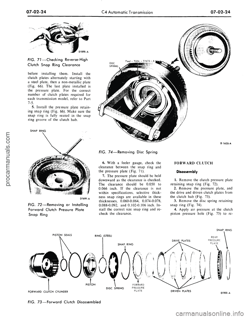
FIG. 71—Checking Reverse-High
Clutch Snap Ring Clearance
before installing them. Install
the
clutch plates alternately starting with
a steel plate, then
a
non-metallic plate
(Fig.
66). The
last plate installed
is
the pressure plate.
For the
correct
number
of
clutch plates required
for
each transmission model, refer
to
Part
7-5.
5.
Install
the
pressure plate retain-
ing snap ring
(Fig. 66).
Make sure
the
snap ring
is
fully seated
in the
snap
ring groove
of the
clutch
hub.
SNAP RING
D1899-A
Tool
-
T65L
-
77575
- A
DISC
ii—mi
-
SPRING
FIG. 72—Removing or Installing
Forward Clutch Pressure Plate
Snap Ring
FIG. 74—Removing Disc Spring
6. With
a
feeler gauge, check
the
clearance between
the
snap ring
and
the pressure plate
(Fig. 71).
7.
The
pressure plate should
be
held
downward
as the
clearance
is
checked.
The clearance should
be
0.050
to
0.066 inch.
If the
clearance
is not
within specifications, selective thick-
ness snap rings
are
available
in
these
thicknesses, 0.060-0.064, 0.074-0.078,
0.088-0.092,
and
0.102-0.106 inch.
In-
stall
the
correct size snap ring
and re-
check
the
clearance.
D 1635-A
FORWARD CLUTCH
Disassembly
1.
Remove
the
clutch pressure plate
retaining snap ring
(Fig. 72).
2.
Remove
the
pressure plate,
and
the drive
and
driven clutch plates from
the clutch
hub (Fig. 73).
3.
Remove
the
disc spring retaining
snap ring
(Fig. 74).
4.
Apply
air
pressure
at the
clutch
piston pressure hole
(Fig. 75) to re-
SNAP RING
PISTON SEALS
RING (STEEL)
FORWARD CLUTCH CYLINDER
DRIVEN PLATES
D1900-A
FIG. 73—Forward Clutch Disassembledprocarmanuals.com
Page 333 of 413

07-02-25
C4 Automatic Transmission
07-02-25
7oo/-
7000-
FIG. 75—Removing Forward
Clutch Piston
move the piston from the clutch hub.
5.
Remove the clutch piston outer
seal and the inner seal from the clutch
hub (Fig. 73).
Assembly
1.
Install new clutch piston seals on
the clutch piston and drum. Lubricate
the seals with clean transmission fluid.
2.
Install the clutch piston into the
clutch hub. Install the disc spring and
retaining snap ring (Fig. 73).
3.
Install the lower pressure plate
with the flat side up and the radius
side downward. Install one non-
metallic clutch plate and alternately
install the drive and driven plates. Be-
fore installing new composition clutch
plates,
soak them in transmission fluid
for fifteen minutes. The last plate in-
stalled will be the upper pressure
plate. Refer to Part 7-5 for the correct
number of clutch plates for the appli-
cable model transmission.
4.
Install the pressure plate retain-
ing snap ring (Fig. 73). Make sure the
snap ring is fully seated in the ring
groove of the clutch hub.
5.
With a feeler gauge, check the
clearance between the snap ring and
the pressure plate (Fig. 76). Down-
CHECK BETWEEN SNAP RING
AND PRESSURE PLATE
FIG. 76—Checking Forward
Clutch Snap Ring Clearance
ward pressure on the plate should be
used when making this check. The
clearance should be 0.026 to 0.042
inch for PEA and PEE models, or
0.020 to 0.036 inch for PEB models.
6. If the clearance is not within
specifications, selective snap rings are
available in these thicknesses: 0.060-
0.064, 0.074-0.078, 0.088-0.092, and
0.102-0.106 inch. Insert the correct
size snap ring and recheck the clear-
ance.
FORWARD CLUTCH HUB
AND RING GEAR
Disassembly
1.
Remove the forward clutch hub
retaining snap ring (Fig. 77).
SNAP RING
RING GEAR
FORWARD
CLUTCH HUB
D1903-A
FIG. 77—Forward Clutch Hub
and Ring Gear Disassembled
2.
Remove the forward clutch hub
from the ring gear.
3.
Press the bushing from the
clutch hub as shown in Fig. 78.
Tool - T66L-7003-B10
Handle
REMOVAL
Assembly
1.
Install a new bushing into the
clutch hub as shown in Fig. 78.
2.
Install the forward clutch hub in
the ring gear. Make sure the hub is
bottomed in the groove of the ring
gear.
3.
Install the front clutch hub re-
taining snap ring. Make sure the snap
ring is fully seated in the snap ring
groove of the ring gear.
INPUT SHELL AND SUN
GEAR
Disassembly
1.
Remove the external snap
from the sun gear (Fig. 79).
ring
EXTERNAL SNAP RING
SUN GEAR
D1904-A
FIG. 79—Removing or Installing
Sun Gear External Snap Ring
2.
Remove thrust washer No. 5
from the input shell and sun gear (Fig.
80).
3.
From inside the input shell, re-
move the sun gear. Remove the inter-
nal snap ring from the sun gear.
Handle
Tool - T66L-V003-B5
INSTALLATION D 1736-A
FIG. 78 — Replacing Forward Clutch Hub Bushingprocarmanuals.com