1969 FORD MUSTANG clutch
[x] Cancel search: clutchPage 400 of 413

07-04-31
C-6 Automatic Transmission
07-04-31
ing. Install six of the seven mounting
bolts and torque them to specifica-
tion.
24.
Adjust the intermediate band as
detailed in Section 2 and install the
input shaft with the long splined end
inserted into the forward clutch as-
sembly.
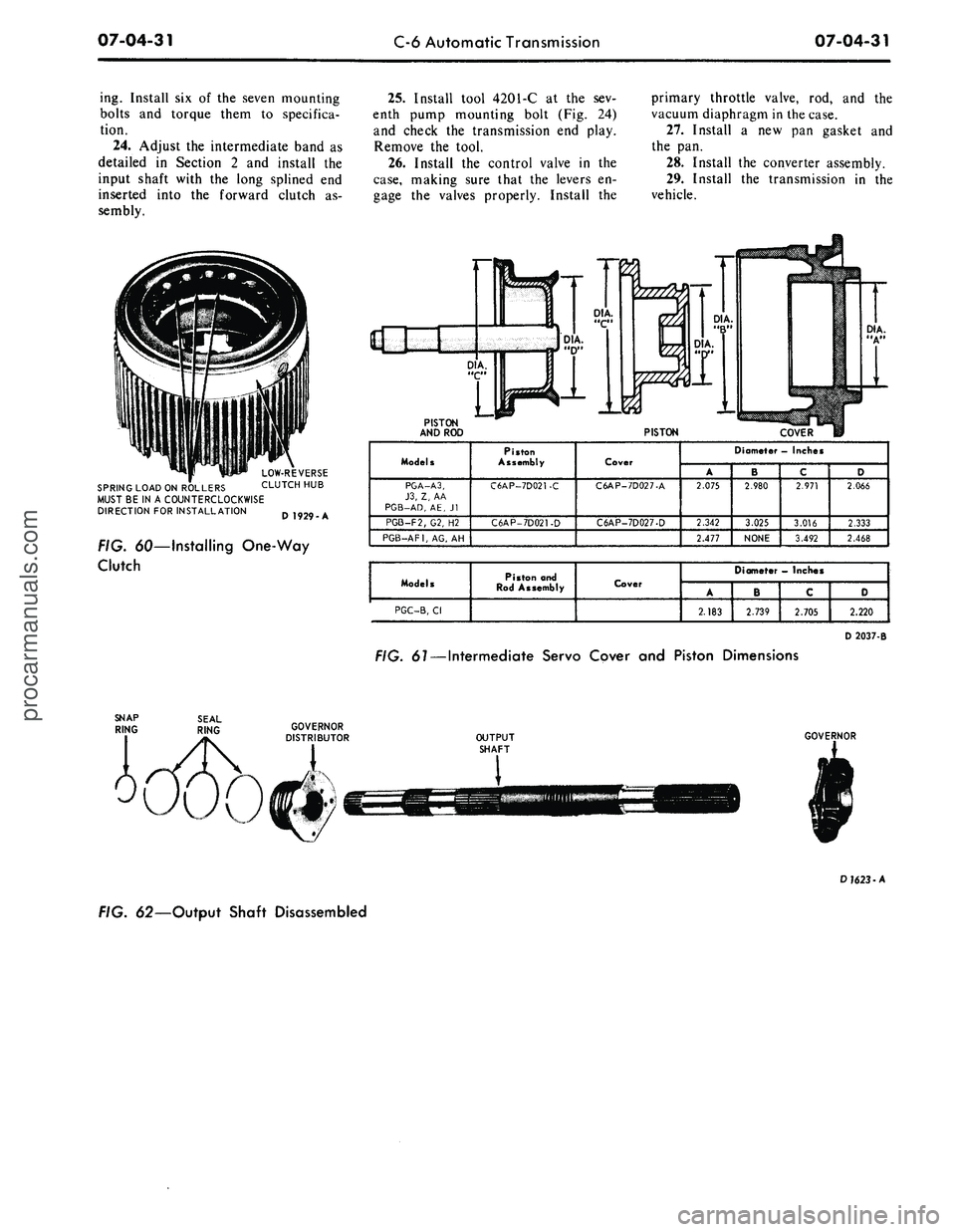
LOW-REVERSE
SPRING LOAD ON ROLLERS CLUTCH HUB
MUST BE IN A COUNTERCLOCKWISE
DIRECTION FOR INSTALLATION Q 192O A
FIG. 60—Installing One-Way
Clutch
25.
Install tool 4201-C at the sev-
enth pump mounting bolt (Fig. 24)
and check the transmission end play.
Remove the tool.
26.
Install the control valve in the
case,
making sure that the levers en-
gage the valves properly. Install the
primary throttle valve, rod, and the
vacuum diaphragm in the case.
27.
Install a new pan gasket and
the pan.
28.
Install the converter assembly.
29.
Install the transmission in the
vehicle.
PISTON
AND ROD
PISTON
COVER
Models
PGA-A3,
J3,
Z, AA
PGB-AD,
AE, Jl
PGB-F2/G2, H2
PGB-AF1,
AG, AH
Piston
Assembly
C6AP-7D021-C
C6AP-7D021-D
Cover
C6AP-7D027-A
C6AP-7D027-D
Diameter - Inches
A
2.075
2.342
2.477
' B
2.980
3.025
NONE
c
2.971
3.016
3.492
D
2.066
2.333
2.468
Models
PGC-B,
Cl
Piston and
Rod Assembly
Cover
Diameter
—
Inches
A
2.183
B
2.739
C
2.705
D
2.220
D 2037-B
FIG.
61
— Intermediate Servo Cover and Piston Dimensions
OUTPUT
SHAFT
GOVERNOR
D
1623
-A
FIG. 62—Output Shaft Disassembledprocarmanuals.com
Page 403 of 413

07-05-03
Specifications
07-05-03
C6 TRANSMISSION (Continued)
Manifold Vacuum
17
16
15
14
13
12
11
Barometric Pressure at 29.5 Inches <2)
T.V.
11-14
15-18
20-22
23-26
28-31
32-35
36-40
Cont.
56-69
56-75
56-S4
56-92
56-98
56-105
56-111
Barometric Pressure at 24.5 Inches ®
T.V.
0-1
2-5
7-9
10-13
15-18
19-22
23-27
Cont.
49-56
49-56
49-61
56-67
56-75
56-84
56-92
© It may not be possible to obtain 18 inches of engine vacuum at idle. For idle vacuums of less than 18 inches the following table
provides idle speed pressure specifications in D range:
£> These specifications (with altitude compensating diaphragm) apply at observed barometric pressure of 29.5 inches (nominal sea level)
© Specifications for barometric pressures of less than 29.5 inches.
At barometric pressures between 29.5 inches and 24.5 inches idle, pressures should fall between the values shown.
CHECK
SAND ADJUSTMENTS
FMX TRANSMISSION
Operation
Transmission End Play Check
Turbine and Stator End Play Check
Front Band Adjustment (Use 1/4 inch spacer
between adjustment screw and servo piston
stem)
Rear Band Adjustment, Model PHB-A.PHD
Rear Band Adjustment,
Model PHB-C, D, E, F, G, H
Primary Sun Gear Shaft Ring End Gap Check
Rear Clutch Selective Snap Ring Thicknesses
Specification
0.010-0.029 (Selective Thrust Washers Available)
PHB,
PHD-New or rebuilt 0.023 max., Used 0.030 max.®
Adjust screw to 10 in-lbs torque. Remove spacer, then tighten screw an additional 3/4 turn
and lock.
Adjust screw to 10 in-lbs torque. Remove spacer, then tighten screw an addition 3/4 turn
Adjusting Internally: Loosen internal locknut. Install spacer tool number T69P-7B193-A between
internal adjusting screw and servo piston, tighten internal adjusting screw to 24 in-lbs torque.
Back off 1 1/2 turns. Hold screw and tighten locknut. Remove spacer.
Adjusting Externally: Loosen internal locknut and reset internal adjusting screw to 0.27-0.28
inch.
Tighten internal locknut. Loosen external locknut and adjust external adjusting screw to 10 ft-lbs
torque. Back off 1 1/2 turns. Hold screw and tighten locknut.
0.002-0.009
0.060-0.064, 0.074-0.078, 0.080-0.092, 0.102-0.106
® To check end play, exert force on checking tool to compress turbine to cover thrust washer wear plate. Set indicator at zero.
C4 TRANSMISSION
Operation
Transmission End Play
Turbine and Stator End Play
Intermediate Band Adjustment
Low-Reverse Band Adjustment
Selective Snap Ring Thickness
Specification
0.008-0.042 inch (Selective Thrust Washers Available)
Model PEB -New or rebuilt 0.044 max., Used 0.060 max.
Model PEE, PEA New or rebuilt 0.023 max., Used 0.040 max.
Remove and discard lock nut. Adjust screw to 10 ft-lbs torque, then back off
1-3/4 turns. Install new lock nut and torque to specification.
Remove and discard lock nut. Adjust screw to 10 ft-lbs torque, then back off 3 turns.
Install new locknut and torque to specification.
0.102-0.106, 0.088-0.092, 0.074-0.078, 0.060-O.064procarmanuals.com
Page 404 of 413

07-05-04
Specifications
07-05-04
C6 TRANSMISSIONS
Operation
Transmission End Play
Turbine and Stator End Play
Intermediate Band Adjustment
Forward Clutch Pressure
Plat eto-Snap Ring Clearance
Selective Snap Ring Thicknesses
Reverse-High Clutch Pressure
Plate-to-Snap Ring Clearance
Selective Snap Ring Thicknesses
Specification
0.008-0.044 (Selective Thrust Washers Available)
New or rebuilt 0.021 max., Used
0.030
max. G)
Remove and discard lock nut. Adjust screw to 10 f
t
-
lbs
torque, then back off 1
turn,
install new lock nut and tighten lock nut to specification.
0.031-0.044
0.056-0.060, 0.065-0.069, 0.074-0.078, 0.083-0.087, 0.092-0.096
Transmission Models
PGA
0.022-0.036
PGB,
PGC
0.027-0.043
0.065-0.069, 0.074-0.078, 0.083-0.087
(D To check end play, exert force on checking tool to compress turbine to cover thrust washer wear plate. Set indicator at zero.
SELECTIVE THRUST WASHERS
FMX TRANSMISSION
Identification No.
By Thickness
Thrust Washer Thickness -Inch
0.061-0.063
0.067-0.069
Identification No.
By Thickness.
Thrust Washer Thickness - Inch
0.074-0.076
0.081-0.083
C4 TRANSMISSION
Nylon Thrust Washer
W/Tangs
0.053-4.0575
0.070-0.074
0.087-0.091
0.104-0.108
0.121-0.125
THRUST WASHER NO. 1
Color Of
Washer
Red
Green
Natural (White)
Black
Yellow
No.
Stamped
On Washer
1
2
3
4
5
THRUST WASHER NO. 2
Metal Thrust
Washer
0.041-0.043
0.056-O.058
0.073-0.075
0.090-0.092
0.107-0.109
C6 TRANSMISSION
Identification No.
1
2
3
Thrust Washer Thickness -Inch
0.056-0.058
a.073-0.07F
0.088-0.090
Identification No.
4
5
Thrust Washer Thickness - Inch
0.103-0.105
0.118-0.120
CLUTCH PLATES
FMX TRANSMISSION
Transmission
Model
PHB,
PHD
FORWARD CLUTCH
Steel
Plates
4
Friction
Plates
5©
Selective Plate
Thicknesses
0.0605-0.063
0.0785-0.081
0.0965-0.099
Selective Plate
Identification
No Stripe
One Stripe
Two Stripes
REAR CLUTCH
Steel
Plates
5®
Friction
Plates
4
Free Pack
Clearance
0.030-0.055
© Last plate (Friction) in FMX forward clutch is selective. Install thickest plate in pack that will be a minimum of 0.010 inch below input shaft shoulder
in cylinder. All other friction plates in* pack are thinnest available.
© Plus one waved plate installed between two steel plates at piston end of pack.procarmanuals.com
Page 405 of 413

07-05-05
Specifications
07-05-05
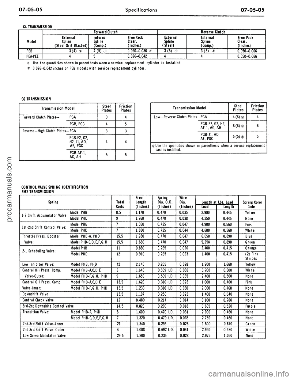
C4 TRANSMISSION
Model
PEB
PEA-PEE
Forward Clutch
External
Spline
(Steel-Grit Blasted)
3(4) '.,
4
Internal
Spline
(Comp.)
4
(5)
>.r<
5
Free Pack
Clear.
(Inches)
0.020-0.036 <*
0.026-0.042
Reverse Clutch
External
Spline
(Steel)
3(5) j)
4
Internal
Spline
(Comp.)
3(3)
J>
4
Free Pack
Clear.
(Inches)
0.050-0.066
0.050-0.066
i Use the quantities shown in parenthesis when a service replacement cylinder is installed.
$•
0.026-0.042 inches on PEB models with service replacement cylinder.
C6 TRANSMISSION
Transmission Model
Forward Clutch Plates- PGA
PGB,
PGC
Reverse-High Clutch Plates-PGA
PGB-F2,
G2,
H2J1,
AD,
AE,
PGC
PGB-AF-1,
AG,
AH
Steel
Plates
3
4
3
4
5
Friction
Plates
4
5
3
4
5
Transmission Model
Low-Reverse Clutch Plates-PGA
PGB-F2,
G2, H2,
AF-1,
AG,
AH
PGB-J1,
AD,
AE,
PGC
Steel
Plates
4(6)®
6(6)©
5(5)®
Friction
Plates
4
6
5
©Use the quantities shown in parenthesis when a service replacement
case is installed.
CONTROL VALVE SPRING IDENTIFICATION
FMX TRANSMISSION
Spring
1 2 Shift Accumulator Valve '° C
Model
PHD
W °nri Shift Pnntrnl Vilur
Model PHD
Throttle Press. Booster Model PHB-A, PHD
Valve:
Model PHB-C,D,E,F,G,H
M Scheduling Valve-
M°delPHB
. 1 Scheduling Valve. Mode, PHD
Low Inhibitor Valve: Model PHB, PHD
Control Oil Press. Comp. Model PHB-A,C,D,E
Valve-Outer: Model PHB-F,G,H, PHD
Control Oil Press. Comp. Model PHB-A,C,D,E
Valve-Inner: Model PHB-F,G,H, PHD
Downshift Valve
Control Check Valve
3rd-2ndDownshift Control Valve
Transition Valve: Model PHB-A, PHD
Model PHB-C,D,E,F,G,H
2nd-3rd Shift Valve-Inner
2nd-3rd Shift Valve-Outer
Low Servo Modulator Valve
Total
Coils
8.5
9
7
7
15.5
15.5
11
12
42
8
9
13.5
13.5
13.5
12
14.5
8
7
21
4
29.5
Free
Length
(Inches)
1.170
1.260
1.650
1.880
1.980
1.660
0.880
0.910
2.140
1.640
1.650
1.620
1.230
1.107
0.480
0.820
1.600
1.320
1.340
1.008
1.800
Spring
Dia.
O.D.
(Inches)
0.470
0.470
0.725
0.725
0.470
0.470
0.265
0.265
0.205
0.509
I.D.
0.509
I.D.
0.310
I.D.
0.310 I.D.
0.250
0.214
0.200
0.470
I.D.
0.470
I.D.
0.295
0.692
I.D.
0.235
Wire
Dia.
(Inches)
0.035
0.038
0.047
0.044
0.047
0.047
0.026
0.023
0.028
0.038
0.035
0.023
0.030
0.023
0.014
0.018
0.031
0.035
0.028
0.041
0.028
Length
at Lbs.
Load
Load
2.900
4.250
4.900
4.600
6.650
5.250
2.400
1.400
1.900
3.200
2.400
1.000
2.000
1.400
0.100
0.605
2.000
2.750
1.500
2.950
2.975
Length
0.445
0.445
0.560
0.560
0.890
0.890
0.415
0.415
1.660
0.500
0.500
0.460
0.460
0.640
0.280
0.520
0.460
0.460
0.670
0.430
1.050
Spring Color
Code
Yel.ow
None
Pin<
White
Blue
Green
Orange
(2) Pink
Stripes
Yellow
Whte
None
Pink
None
None
None
Purple
None
None
Green
White
Noneprocarmanuals.com
Page 413 of 413

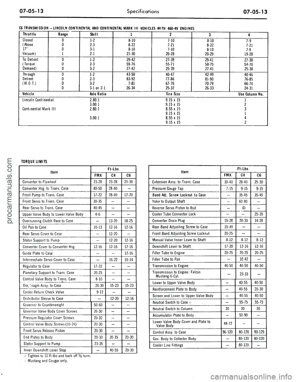
07-05-13
Specifications
07-05-13
C6 TRANSMISSION -LINCOLN CONTINENTAL AND CONTINENTAL MARK III VEHICLES WITH 460-4V ENGINES
Throttle
Closed
(Above
17"
Vacuum)
To Detent
(Torque
Demand)
Through
Detent
(W.O.T.)
Range
D
D
D
1
D
D
D
D
D
D
D
Vehicle
Lincoln Continental
Continental Mark III
Shift
1-2
2-3
3-1
2-1
1-2
2-3
3-2
1-2
2-3
3-2
3-1 or 2-1
Axle Ratio
2.80:1
3.00:1
2.80:1
3.00:1
1
8-10
8-22
8-10
21-30
29-42
59-76
27-42
43-50
83-92
2-81
26-34
2
7-10
7-21
7-10
20-28
27-39
55-71
25-39
40-47
77-86
67-76
25-32
Tire Size
9.15 x 15
9.15x15
8.55 x 15
9.15 x 15
8.55 x 15
9.15 x 15
3
8-10
8-22
8-10
20-29
29-41
58-75
27-41
42-49
81-90
70-79
26-33
4
7-9
7-21
7-9
19-28
27-38
54-70
25-38
40-46
76-85
66-74
24-31
Use Column No.
1
2
3
1
4
2
TORQUE LIMITS
Item
Converter to Flywheel
Converter Hsg. to Trans. Case
Front Pump to Trans. Case
Front Servo to Trans. Case
Rear Servo to Trans. Case
Upper Valve Body to Lower Valve Body
Overrunning Clutch Race to Case
Oil Pan to Case
Rear Servo Cover to Case
Stator Support to Pump
Converter Cover to Converter Hsg.
Guide Plate to Case
Intermediate Servo Cover to Case
Regulator to Case
Planetary Support to Trans. Case
Control Valve Body to Trans. Case
Dia;
'iragm Assy, to Case
Cooler Return Check Valve
Distributor Sleeve to Case
Governor to Counterweight
Governor Valve Body Cover Screws
Pressure Regulator Cover Screws
Control Valve Body Screws (10-24)
Front Servo Release Piston
End Plates to Body
Stator Support to Pump
Inner Downshift Lever Stop
Ft-Lbs
FMX
23-28
40-50
17-22
30-35
40-45
4-6
—
10-13
-
-
12-16
-
-
17-22
20-25
8-10
20-30
9-12
-
50-60
20-30
20-30
20-30
20-30
20-30
23-35
-
C4
23-28
28-40
28-40
-
-
-
13-20
12-16
12-20
12-20
12-16
-
16-22
-
-
-
15-23
-
12-20
-
-
-
-
-
20-35
-
40-55
C6
20-30
-
12-20
-
-
-
18-25
12-16
-
12-16
12-16
12-16
10-14
-
-
-
15-23
-
12-16
-
-
-
-
-
20-30
-
20-30
Item
Extension Assy, to Trans. Case
Pressure Gauge Tap
Band Adj. Screw Locknut to Case
Yoke to Output Shaft
Reverse Servo Piston to Rod
Cooler Tube Connector Lock
Converter Drain Plug
Rear Band Adjusting Screw to Case
Front Band Adjusting Screw Locknut
Manual Valve Inner Lever to Shaft
Downshift Lever to Shaft
Filler Tube to Engine
Filler Tube to Pan
Transmission to Engine
Transmission to Engine: Falcon
Mustang-6-Cyl.
Lower to Upper Valve Body
Reinforcement Plate to Body
Screen and Lower to Upper Valve Body
Neutral Switch to Case 2^
Neutral Switch to Column
Accumulator Plate to Body
Lower Valve Body Cover and Plate to
Valve Body
Control Assy, to Case
Gov. Body to Collector Body
Cooler Line Fittings
Ft-Lbs
FMX
30-40
7-15
-
-
-
-
15-28
35-40
20-25
8-12
17-20
20-25
-
40-50
-
-
- ;
-
-
20
-
48-72
96-120
-
-
C4
28-40
9-15
35-45
60-80
®
-
20-30
-
-
8-12
12-16
20-25
32-42
40-50
23-33
40-55
40-55
40-55
55-75
20
50-90
-
80-120
80-120
80-120
C6
25-30
9-15
35-45
-
-
25-35
14-28
-
-
8-12
12-16
20-25
-
40-50
-
40-50
20-30
40-50
55-75
20
-
-
90-125
80-120
-
r^ Tighten to 10 ft-lbs and back off 5/8
turn.
-• Mustang and Cougar only.procarmanuals.com