1969 FORD MUSTANG differential
[x] Cancel search: differentialPage 41 of 413
02-02-22
Brake System
02-02-22
BRAKE VACUUM BOOSTER -2005
AUTOMATIC I
TRANSMISSION
HAIR PIN RETAINER
330699-S2
SPACER
STOP LIGHT SWITCH-13480
STANDARD
TRANSMISSION
BUSHING
BUSHING
PUSH ROD
BRAKE PEDAL ASSEMBLY
CLUTCH
PEDAL
ASSEMBLY
H 1557-C
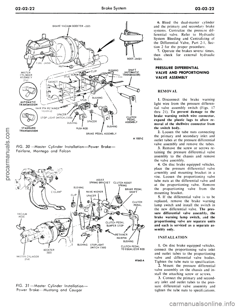
FIG. 30—Master Cylinder Installation—Power Brake-
Fairlane, Montego and Falcon
ASSIST
SPRING BRACKET CLUTCH ASSIST
\ SPRING
BRAKE PEDAL
SHAFT
CLUTCH
PEDAL
CLUTCH PEDAL
TO EQUALIZER ROD
HI643-
A
FIG. 31—Master Cylinder Installation-
Power Brake—Mustang and Cougar
6. Bleed the dual-master cylinder
and the primary and secondary brake
systems. Centralize the pressure dif-
ferential valve. Refer to H>draulic
System Bleeding and Centralizing of
the Differential Valve, Part 2-1, Sec-
tion 2 for the proper procedure.
7.
Operate the brakes several times,
then check for external hydraulic
leaks.
PRESSURE DIFFERENTIAL
VALVE AND PROPORTIONING
VALVE ASSEMBLY
REMOVAL
1.
Disconnect the brake warning
light wire from the pressure differen-
tial valve assembly switch (Figs. 17
thru 21). To prevent damage to the
brake warning switch wire connector,
expand the plastic lugs to allow re-
moval of the shellwire connector from
the switch body.
2.
Loosen the tube nuts connecting
the primary and secondary inlet and
outlet tubes at the pressure differential
valve assembly and remove the tubes.
3.
Remove the screw or screws re-
taining the pressure differential valve
assembly to the chassis and remove
the valve assembly.
4.
On disc brake equipped vehicles,
place the pressure differential valve
assembly and mounting bracket in a
vise.
Loosen the proportioning valve
tube nuts at the differential valve and
at the proportioning valve. Remove
the proportioning valve from the
mounting bracket.
5.
If the differential valve is to be
replaced, remove the brake warning
lamp switch and install the switch in
the new differential valve. The pres-
sure differential valve assembly, the
brake warning lamp switch, and the
proportioning valve are separate units
and each is serviced as a separate as-
sembly only.
INSTALLATION
1.
On disc brake equipped vehicles,
connect the proportioning valve inlet
and outlet tubes to the proportioning
valve and differential valve bodies.
Tighten the tube nuts to specification.
2.
Mount the pressure differential
valve assembly on the chassis and in-
stall the attaching screw or screws.
3.
Connect the primary and second-
ary inlet and outlet tubes to the pres-
sure differential valve assembly and
tighten the tube nuts to specifications.procarmanuals.com
Page 42 of 413
02-02-23
Brake System
02-02-23
BOOSTER ASSEMBLY- 2005
NUT-34444-S7
HOSE 2A047
MASTER CYLINDER
IDENTIFICATION
BRAKE TUBE-2263
BRAKE TUBE -2264
PRESSURE DIFFERENTIAL
VALVE ASSEMBLY-2B257
BRAKE TUBE-2B255
H 15S3-B
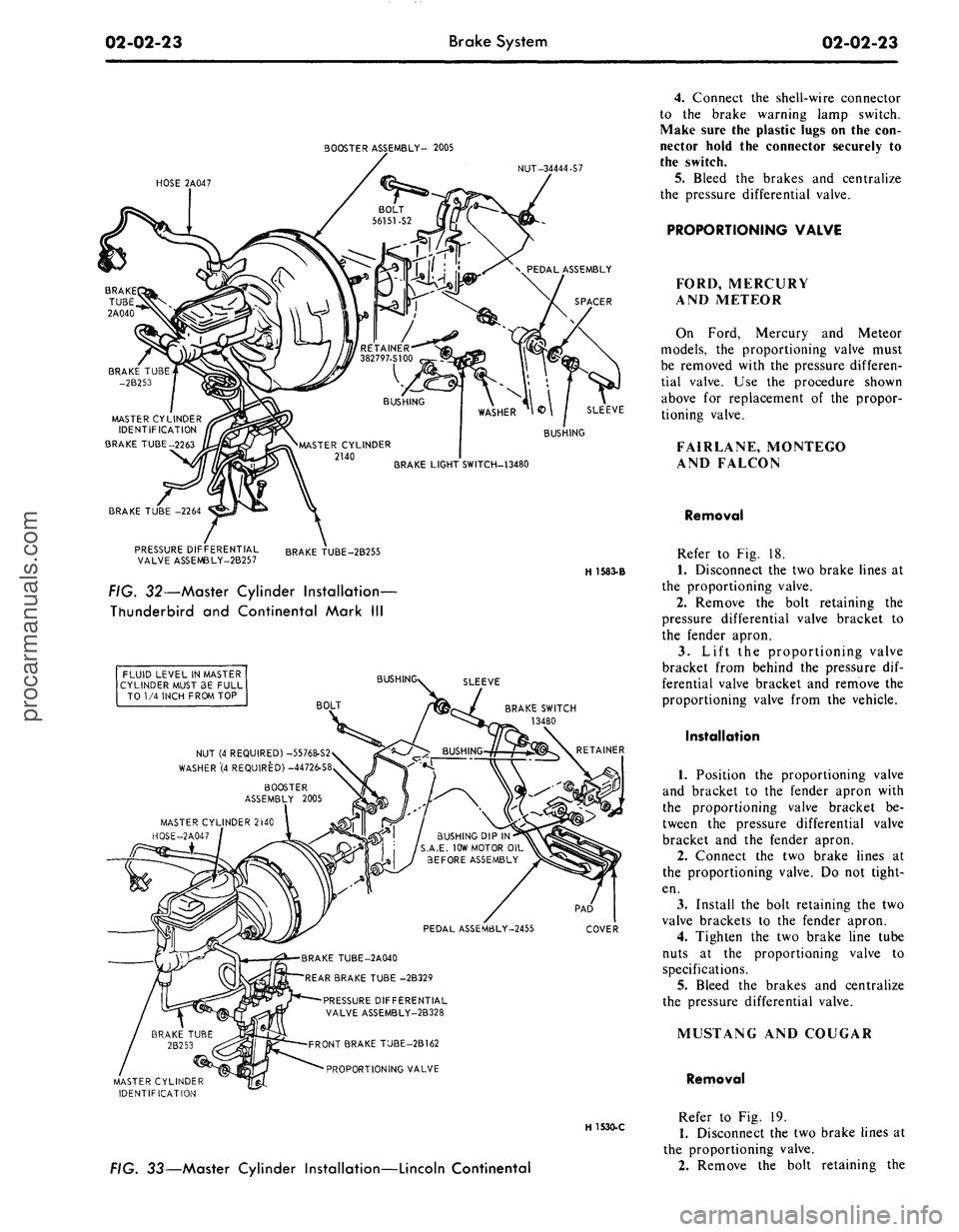
FIG. 32—Master Cylinder Installation-
Thunderbird and Continental Mark III
FLUID LEVEL IN MASTER
CYLINDER MUST 3E FULL
TO 1/4 INCH FROM TOP
BUSH
SLEEVE
BOLT
BRAKE SWITCH
13480
NUT (4 REQUIRED) -55768-S2
WASHER"(4 REQUIRED) -44726-S8
BOOSTER
ASSEMBLY 2005
MASTER CYLINDER 2WO
HOSE-2A047
BUSHING DIP IN
S.A.E. 10W MOTOR OIL
BEFORE ASSEMBLY
PEDAL ASSEM6LY-2455
COVER
BRAKE TUBE-2A040
REAR BRAKE TUBE -2B329
PRESSURE DIFFERENTIAL
VALVE ASSEMBLY-2B328
FRONT BRAKE TUBE-2B162
PROPORTIONING VALVE
MASTER CYLINDER
IDENTIFICATION
H 1530-C
FIG. 33—Master Cylinder Installation—Lincoln Continental
4.
Connect the shell-wire connector
to the brake warning lamp switch.
Make sure the plastic lugs on the con-
nector hold the connector securely to
the switch.
5. Bleed the brakes and centralize
the pressure differential valve.
PROPORTIONING VALVE
FORD, MERCURY
AND METEOR
On Ford, Mercury and Meteor
models, the proportioning valve must
be removed with the pressure differen-
tial valve. Use the procedure shown
above for replacement of the propor-
tioning valve.
FAIRLANE, MONTEGO
AND FALCON
Removal
Refer to Fig. 18.
1.
Disconnect the two brake lines at
the proportioning valve.
2.
Remove the bolt retaining the
pressure differential valve bracket to
the fender apron.
3.
Lift the proportioning valve
bracket from behind the pressure dif-
ferential valve bracket and remove the
proportioning valve from the vehicle.
Installation
1.
Position the proportioning valve
and bracket to the fender apron with
the proportioning valve bracket be-
tween the pressure differential valve
bracket and the fender apron.
2.
Connect the two brake lines at
the proportioning valve. Do not tight-
en.
3.
Install the bolt retaining the two
valve brackets to the fender apron.
4.
Tighten the two brake line tube
nuts at the proportioning valve to
specifications.
5.
Bleed the brakes and centralize
the pressure differential valve.
MUSTANG AND COUGAR
Removal
Refer to Fig. 19.
1.
Disconnect the two brake lines at
the proportioning valve.
2.
Remove the bolt retaining theprocarmanuals.com
Page 43 of 413
02-02-24
Brake
System
02-02-24
proportioning valve to the fender
apron and remove the proportioning
valve.
Installation
1.
Position the proportioning valve
to the fender apron.
2.
Connect the two brake lines at
the proportioning valve. Do not tight-
en.
3.
Install the bolt retaining the pro-
portioning valve to the fender apron.
4.
Tighten the brake line tube nuts
at the proportioning valve to specifica-
tions.
5.
Bleed the brakes and centralize
pressure differential valve.
THUNDERBIRD AND
CONTINENTAL MARK III
Removal
Refer to Fig. 20.
1.
Disconnect the two hydraulic
brake lines at the master cylinder.
2.
Remove the two nuts retaining
the master cylinder to the booster and
remove the master cylinder for clear-
ance.
3.
Disconnect the two brake lines at
the proportioning valve.
4.
Remove the bolt and nut retain-
ing the proportioning valve to the
pressure differential valve bracket and
remove the proportioning valve assem-
bly.
Installation
1.
Transfer the bracket to the new
proportioning valve.
2.
Position the proportioning valve
assembly to the pressure differential
valve bracket.
3.
Connect the two brake lines to
the proportioning valve. Do not tight-
en.
4.
Install the bolt and nut retaining
the proportioning valve to the pressure
differential valve bracket.
5.
Tighten the two brake line tube
nuts at the proportioning valve to
specifications.
6. Position the master cylinder to
the booster and install the nuts retain-
ing the master cylinder to the booster.
7.
Connect the two brake lines at
the master cylinder and tighten the
tube nuts to specifications.
8. Bleed the brakes and centralize
the pressure differential valve.
LINCOLN CONTINENTAL
Removal
Refer to Fig. 21.
1.
Disconnect the two brake lines at
the proportioning valve.
2.
Loosen the bolt and nut on the
bracket retaining the proportioning
valve to the chassis.
3.
Remove the proportioning valve
from the bracket.
Installation
- 1. Position the proportioning valve
in the bracket and connect the two
brake lines. Do not tighten.
2.
Tighten the bolt and nut on the
bracket.
3.
Tighten the tube nuts on the
brake lines at the proportioning valve
to specifications.
4.
Bleed the brakes and centralize
the pressure differential valve.
PRESSURE METERING VALVE—
LINCOLN CONTINENTAL
REMOVAL
Refer to Fig. 21.
1.
Loosen the tube nuts connecting
the inlet and outlet tubes at the me-
tering valve, and remove the tubes.
2.
Remove the two screws retaining
the metering valve to the frame
crossmember, and remove the me-
tering valve. The metering valve is ser-
viced as an assembly only.
INSTALLATION
1.
Position the metering valve to
the frame crossmember, and install
the retaining screws.
2.
Connect the inlet and outlet
tubes to the metering valve, and tight-
en the tube nuts to specification.
BRAKE BOOSTER
REMOVAL
1.
Working from inside the\ vehicle
below the instrument panel, disconnect
the booster push rod from the brake
pedal assembly. To do this, proceed as
follows:
Disconnect the stop light switch
wires at the connector. Remove the
hairpin retainer. Slide the stop light
switch off from the brake pedal pin
just far enough for the switch outer
hole to clear the pin, and then remove
the switch from the pin and booster
push rod. Be careful not to damage
the switch during removal. Slide the
booster push rod and the nylon wash-
ers and bushing off the brake pedal
pin (Figs. 29 thru 33).
2.
Open the hood and remove the
master cylinder from the booster. Se-
cure it to one side without disturbing
the hydraulic lines. It is not necessary
to disconnect the brake lines, but care
should be taken that the brake lines
are not deformed. Permanent defor-
mation of brake lines can lead to tube
failure.
3.
Disconnect the manifold vacuum
hose or hoses from the booster unit.
4.
Remove the booster-to-dash
panel attaching nuts or bolts (Figs. 29
thru 33). Remove the booster and
bracket assembly from the dash panel,
sliding the push rod link out from the
engine side of the dash panel.
5.
On Fairlane, Montego, and Fal-
con models, remove the push rod link
boot from the dash panel.
INSTALLATION
1.
On Fairlane, Montego and Fal-
con models, install the push rod link
boot in the hole in the dash panel as
shown in Fig. 23. Install the four
spacers on the mounting studs.
2.
Mount the booster and bracket
assembly to the dash panel by insert-
ing the push rod or push rod link in
through the hole and boot in the dash
panel. Install the bracket-to-dash
panel attaching lock nuts or bolts
(Figs.
29 thru 33).
3.
Connect the manifold vacuum
hose or hoses to the booster.
4.
Before installing the master cyl-
inder, check the distance from the
outer end of the booster assembly
push rod to master cylinder surface.
Turn the screw in or out to obtain the
specified length. Refer to Part 2-1,
Section 2, Power Brake Master Cylin-
der Push Rod Adjustment. Install the
master cylinder and torque the attach-
ing nuts to specifications.
5.
Working from inside the vehicle
below the instrument panel, connect
the booster push rod link to the brake
pedal assembly. To do this, proceed as
follows:
Install the inner nylon washer, the
booster push rod, and the bushing on
the brake pedal pin. Position the
switch so that it straddles the push
rod with the switch slot on the pedal
pin and the switch outer hole justprocarmanuals.com
Page 56 of 413

FROM MASTER CYLINDER
ACTUATOR AIR FILTER
EXISTING SCREW
VIEW IN CIRCLE
W
SOLENOID
ACTUATOR TO REA
BRAKE TUBE
DIFFERENTIAL VALVE
UATORTUBE
VIEW IN CIRCLE T
FROM ACTUATOR
TO REAR BRAKES
GLOVE BOX
CONTROL MODULE
VIEW V
VIEW U
H1653-A
FIG. 39—Anti-Skid Control Systemprocarmanuals.com
Page 57 of 413
02-02-38
Brake System
02-02-38
2.
Disconnect the actuator solenoid
and warning switch harness connectors
from the control module.
3.
Remove the two wiring harness
grommets from the dash panel and
push the wiring harness and connec-
tors through the openings in the dash
panel.
4.
Working in the engine compart-
ment loosen the hose clamp and re-
move the air hose from the air filter.
5.
Remove the engine air cleaner-
Loosen the hose clamp and remove
the vacuum hose from the vacuum
manifold fitting.
6. Raise the vehicle on a hoist.
7.
Disconnect the exhaust pipes
from the exhaust manifold and sup-
port with wire to provide access to the
actuator assembly.
8. Remove the bolt retaining the
actuator ground wire to the rear outer
corner of the engine right bank.
9. Loosen the tube nuts and discon-
nect the brake system hydraulic tubes
from the hydraulic valve housing.
10.
Remove the three nuts retaining
the actuator assembly to the actuator
support bracket.
11.
Remove the three bolts that re-
tain the actuator mounting bracket to
the side rail and remove the mounting
bracket.
12.
Remove the actuator assembly
from the vehicle and place it on a
bench.
13.
Remove the air and vacuum
hoses from the actuator.
INSTALLATION
1.
Install the air and vacuum hoses
on the new actuator.
2.
Place the actuator assembly into
position under the vehicle, routing the
air and vacuum hoses up between the
engine and fender apron and inserting
the solenoid leads through the holes in
the firewall.
3.
Position the ground wire to the
rear of the engine block and install re-
taining bolt.
4.
Position the actuator mounting
bracket to the frame side rail and in-
stall the three retaining bolts.
5.
Position the actuator assembly
to the mounting bracket and install
the three retaining nuts.
6. Connect the hydraulic tubes to
the hydraulic valve assembly and
tighten the tube nuts to specifications.
7.
Connect the exhaust pipes to the
exhaust manifolds.
8. Lower the vehicle.
9. Pull the actuator solenoid and
brake warning switch wiring harness
through the two holes in the dash
panel from inside the car. Seat the
wiring harness grommets in the dash
panel.
10.
Connect the actuator solenoid
and brake warning switch wiring har-
ness connectors to the control mo-
dules.
'
11.
Position the control module in
the bracket under the glove box and
install the retaining screw.
12.
In the engine compartment con-
nect the air hose to the air filter and
position the hose clamp.
13.
Connect the vacuum hose to the
engine vacuum manifold fitting. In-
stall the engine air cleaner.
14.
Bleed the rear brake system and
centralize the pressure differential
valve.
15.
Raise the rear wheels. Apply
the brakes with the rear wheels turn-
ing to verify proper operation of the
anti-skid control system.
ANTI-SKID CONTROL MODULE
REMOVAL
Refer to Fig. 39.
1.
Remove the retaining strap hold-
ing the harnesses.
2.
Remove the screw that attaches
the forward end of the control module
retainer to the support assembly.
3.
Lower the forward end of the
control module and retainer from the
support assembly; move the module
and retainer forward slightly until the
flange clears the slot in the support
assembly.
4.
Disconnect the five wiring har-
ness plugs from the control module.
5.
Remove the control module from
the vehicle.
INSTALLATION
1.
Connect the five wiring harness
plugs to the control module. Only one
arrangement is possible.
2.
Position the control module in
the retainer, orienting the module per
the markings on it, and insert the re-
tainer flange into the slot at the rear
of the support assembly.
3.
Pivot the retainer and control
module upward and align the screw
hole in the forward end of the retainer
with the hole in the support bracket
assembly. Install the retaining screw.
4.
Test the vehicle on the hoist to
verify correct operation of the skid
control system.
5.-
Secure the wiring to the module
support extension with the retaining
strap.
ANTI-SKID CONTROL SENSOR
REMOVAL
Refer to Fig. 39.
1.
Raise the vehicle on a hoist.
2.
Remove the rear wheel and tire
assembly.
3.
Remove the three Tinnerman
nuts (3) and remove the brake drum.
4.
Disconnect the sensor lead from
the rear wiring harness.
5.
Unseat the sensor lead grommet
pushing it to the inside of the brake
assembly.
6. Remove the four nuts that retain
the sensor to the backing plate and
pull the axle shaft, sensor assembly
and wheel bearing assembly from the
axle housing.
7.
Press the wheel bearing retainer
and wheel bearing off the axle shaft
(Refer to Part 4-2).
8. Remove the sensor assembly and
press the rotor off the shaft with tool
T69P-2B384-A Detail 2 and TOOL
1225-DA.
INSTALLATION
1.
Press a new rotor onto the axle
shaft. Install a new sensor assembly
on the shaft with tool T69P-
2B384-ADetail 1 and TOOL 1225-
DA, and press the bearing and bear-
ing retainer onto the shaft (Refer to
Part 4-2).
2.
Insert the axle shaft assembly in
the rear axle housing onto the four
backing plate retaining bolts, feeding
the sensor lead through the hole in the
backing plate.
3.
Seat the sensor lead grommet in
the backing plate.
4.
Install the four nuts on the re-
taining bolts and tighten to specifica-
tions.
5.
Connect the sensor lead to the
rear wiring harness and install two re-
taining straps.
6. Install the rear brake drum and
retain with the Tinnerrhan drum re-
taining nuts.
7.
Install the rear wheel and tire as-
sembly and tighten the wheel nuts to
specifications.
8. Test the vehicle on the hoist to
verify proper operation of the skid
control system.procarmanuals.com
Page 100 of 413

03-02-24
Suspension
03-02-24
LOCK NUT
INSULATOR
NG
NUT
MOUNTING STUD
WASHER
LOCK WASHER
FIG. 31—Rear Shock Absorber Mounting
F1486-A
TRACK BAR
MOUNTING
STUD AXLE
VENT
SHOCK
ABSORBER
MOUNTING
BRACKET
SHOCK
ABSORBER
MOUNTING
BRACKET
V-V.
FIG. 32—Removing or Installing Rear Spring—Typical
COIL SPRING
F1438-A
Place jack stands under the frame side
rails.
2.
Disconnect the lower studs of the
two rear shock absorbers from the
mounting brackets on axle housing.
3.
Lower the hoist and axle housing
until the coil springs are released (Fig.
32).
4.
Remove the springs and the insu-
lators from the vehicle.
Installation
1.
Position the spring in the upper
and lower seats with an insulator be-
tween each seat and the spring.
2.
Raise the hoist and axle housing
with the spring in position and con-
nect the lower studs of the rear shock
absorbers to the mounting brackets on
the axle housing. Install the attaching
nuts,
and torque to specifications.
3.
Remove the jack stands and
lower the vehicle.
REAR SUSPENSION
LOWER ARM
FORD, MERCURY,
METEOR, THUNDERBIRD,
CONTINENTAL MARK III
Removal
1.
Raise the vehicle on a hoist and
place jack stands under the frame side
rails.
2.
Remove the attaching nut and
bolt from the frame track bar mount-
ing bracket and disconnect the bar
from the stud (Fig. 4).
3.
Lower the axle enough to relieve
spring pressure.
4.
Support axle under differential
pinion nose as well as under axle.
5.
Remove the lower arm pivot bolt
and nut from the axle bracket. Then,
disengage the lower arm from the
bracket.
6. Remove the pivot bolt and nut
from the frame bracket and remove
the lower arm from the vehicle.
Installation
The rear suspension lower arms are
not interchangeable. The lower arm
for the left side can be identified by
notches in the bushing flange (Fig. 4).
The right arm does not have the
notches.
1.
Position the lower arm in the
bracket on the frame side rail. Install
a new pivot bolt and new nut (Fig.
33).
Do not tighten the nut at this
time.
2.
Position the lower arm to the
axle bracket and install a new bolt
and new nut (Fig. 33). Do not tighten
the nut at this time.
3.
Raise the axle.
4.
Install alignment spacers be-
tween the rear axle and frame (Fig. 3,
Part 3-1). Then, torque the lower armprocarmanuals.com
Page 101 of 413

03-02-25
Suspension
03-02-25
pivot bolts and nuts to specification
(Part 3-13).
5.
Connect the track bar to the
frame bracket with a new nut and
bolt. Torque the nut to specification
(Part 3-13).
6. Remove the alignment spacers
and jack stands and lower the vehicle.
REAR SUSPENSION-
UPPER ARM
FORD, MERCURY,
METEOR, THUNDERBIRD,
CONTINENTAL MARK HI
Removal
1.
Raise the vehicle and support the
frame side rails with jack stands.
2.
Support the rear axle, then dis
connect the track bar from the frame
bracket.
3.
Lower the axle and support axle
under differential pinion nose, as well
as under axle.
4.
Remove the nut, bolt and two
washers that attach the upper arm to
the axle housing. Disconnect the arm
from the housing.
5.
Remove the nut and bolt that se-
cures the upper arm to the crossmem-
ber and remove the arm.
Installation
1.
Hold the upper arm in place on
the crossmember and install a new at-
taching bolt, a new lockwasher and a
new nut. Do not tighten the nut at this
time.
2.
Secure the upper arm to the axle
housing with a new attaching bolt,
two washers and a new nut. Do not
tighten the nut at this time.
3.
Install alignment spacers be-
tween the rear axle housing and
frame.
4.
Connect the track bar to the
frame bracket with a new nut and
bolt. Torque the nut to specifications.
5.
Torque the upper arm front nut
to specification. Remove the align-
ment spacers and the jack stands.
6. Adjust the pinion angle and tor-
que the rear nut to specification.
7.
Lower the vehicle.
TRACK BAR
FORD, MERCURY,
METEOR, THUNDERBIRD,
CONTINENTAL MARK HI
1.
Raise the vehicle on an axle con-
tact hoist.
FRONT PIVOT BOLT
LOWER ARM
REAR PIVOT BOLT NUT
F1439-A
FIG. 33—Rear Suspension Lower Arm Installed
Tool-T64K-5781-B4 (Thrust
Washer)
FIG. 34—Rear Spring Front Bushing Removal—Typical
F 1485. A
2.
Remove rubber cover at axle at-
tachment on track bar.
3.
Remove the nut and washer at-
taching the track bar to the upper arm
bracket and disengage the track bar
from the mounting stud (Fig. 33).
4.
Remove the nut and bolt attach-
ing the track bar to the frame side rail
and remove the track bar.
5.
Position the track bar to the
frame side rail and install a new at-
taching bolt and new nut.
6. Position the track bar on the
upper arm bracket mounting stud and
install a new washer and a new at-
taching nut. Torque the track bar at-
taching bolt and nuts to specification
(Part 3-13). Lubricate rubber cover
with synthetic rubber lubricant and in-
sert over end of stud onto washer.
Then, lower the vehicle.
REAR SPRING AND/OR BUSHING
COUGAR, FAIRLANE,
FALCON, MONTEGO,
MUSTANG
Removal
1.
Raise the vehicle on a hoist and
place supports beneath the underbody
and under the axle.
2.
Disconnect the lower end of the
shock absorber from the spring clip
plate and push the shock out of the
way. Remove the supports from under
the axle.
3.
Remove the spring clip plate
nuts from the U-bolts; then, remove
the plate (Fig. 31). Raise the rear axle
just enough to remove the weight from
the spring.
4.
Remove the two attaching nuts,
and rear shackle bar, and the two
shackle inner bushings.procarmanuals.com
Page 188 of 413
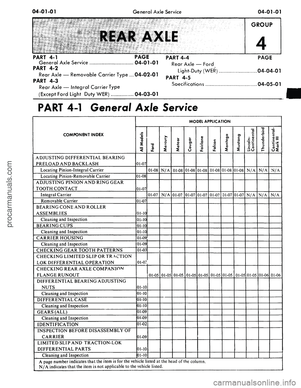
04-01-01
General Axle Service
04-01-01
GROUP
4
PART
4-1
PAGE
General Axle Service 04-01-01
PART 4-2
Rear Axle
—
Removable Carrier Type ... 04-02-01
PART
4-3
Rear Axle
—
Integral CarrierType
(Except Ford Light Duty WER) 04-03-01
PART 4-4
Rear Axle
—
Ford
Light-Duty (WER)
PART
4-5
Soecifications
PAGE
04-04-01
04-05-01
PART
4-1
General Axle Service
COMPONENT INDEX
ADJUSTING DIFFERENTIAL BEARING
PRELOAD AND BACKLASH
Locating Pinion-Integral Carrier
Locating Pinion-Removable Carrier
ADJUSTING PINION AND RING GEAR
TOOTH CONTACT
Integral Carrier
Removable Carrier
BEARING CONE AND ROLLER
ASSEMBLIES
Cleaning
and
Inspection
BEARING CUPS
Cleaning
and
Inspection
CARRIER HOUSING
Cleaning
and
Inspection
CHECKING GEAR TOOTH PATTERNS
CHECKING LIMITED SLIP
OR
TRACTION
LOK DIFFERENTIAL OPERATION
CHECKING REAR AXLE COMPANIOM
FLANGE RUNOUT
DIFFERENTIAL BEARING ADJUSTING
NUTS
Cleaning
and
Inspection
DIFFERENTIAL CASE
Cleaning
and
Inspection
GEARS (ALL)
Cleaning
and
Inspection
IDENTIFICATION
INSPECTION BEFORE DISASSEMBLY
OF
CARRIER
LIMITED SLIP AND TRACTION-LOK
DIFFERENTIAL PARTS
Cleaning
and
Inspection
MODEL APPLICATION
All
Models
01-07
01-08
01-07
01-07
01-10
01-10
01-10
01-10
01-09
01-09
01-03
01-02
01-10
01-10
01-10
01-10
01-09
01-09
01-02
01-09
01-10
01-10
Ford
01-08
01-07
01-05
Mercury
N/A
N/A
01-05
Meteor
01-08
01-07
01-05
Cougar
01-08
01-07
01-05
Fairlane
01-08
01-07
01-05
Falcon
01-08
01-07
01-05
Montego
01-08
01-07
01-05
Mustang
01-08
01-07
01-05
Lincoln-
Continental
N/A
N/A
01-05
Thunderbird
N/A
N/A
01-06
Continental-
Mark
III
N/A
N/A
01-06
A page number indicates that the item
is for
the vehicle listed
at the
head
of
the column.
N/A indicates that the item
is not
applicable
to
the vehicle listed.
procarmanuals.com