1969 FORD MUSTANG brake rotor
[x] Cancel search: brake rotorPage 86 of 413
03-02-10
Suspension
03-02-10
lower
arm
free
to
drop
as
coil spring
tension
is
eased.
If a
chain hoist
or a
jack that
has
a
narrow contact
pad is
to
be
used
on the
bumper
to
raise
the
car, distribute
the
load along
the
bumper
by
using
a
steel plate
3 or 4
inches long
as a
contact
pad to pre-
vent damaging
the
bumper.
2.
If the
ball joint
is
riveted
to the
arm, drill
a
1/8-inch
pilot hole
com-
pletely through each rivet. Then drill
off
the
rivet head through
the
pilot
hole with
a
3/8-inch drill,
and
drive
out both rivets.
3.
Position
a
jack
or
safety stand
under
the
lower
arm, and
lower
the
vehicle about
6
inches
to
offset
the
coil spring tension.
4.
Remove
the
cotter
pin
from
the
ball joint stud,
and
remove
the nut.
5.
Place
a box
wrench over
the
lower
end
of the
tool shown
in
Fig.
7,
and position
the
tool.
The
tool should
seat firmly against
the end of
both
studs,
and
not
against
the
upper stud
nut.
6. Turn
the
wrench until both studs
are under tension,
and
then, with
a
hammer,
tap the
spindle near
the
lower stud
to
loosen
the
stud from
the
spindle.
Do not
loosen
the
stud with
tool pressure alone. Remove
the
ball
joint.
7.
Clean
the end of the arm, and
remove
all
burrs from
the
hole edges.
Check
for
cracks
in the
metal
at the
holes,
and
replace
the arm if it is
cracked.
8. Position
the
stud
of
the
ball joint
to
the
spindle bore,
and
install
the at-
taching
nut
finger-tight.
9. Attach
the
ball joint
to
the
lower
arm.
Use
only
the
specified bolts
and
nuts.
Do not
rivet
the new
ball joint
to
the
arm.
Torque nuts
to
specification.
10.
Torque
the
ball joint stud
nut
to specification,
and
install
a
new cot-
ter
pin.
11.
Remove
the
jack.
12.
Check
and, if
necessary, adjust
caster, camber,
and
toe-in. Whenever
any part
of the
front suspension
has
been removed
and
installed, front
wheel alignment must
be
checked.
BALL JOINT REPLACEMENT
LINCOLN CONTINENTAL
The lower ball joint
is
riveted
to
the
lower
arm
wheras
the
upper ball joint
is bolted
to the
upper
arm.
When
re-
placing
a
ball joint,
use all the
parts
supplied
in the kit.
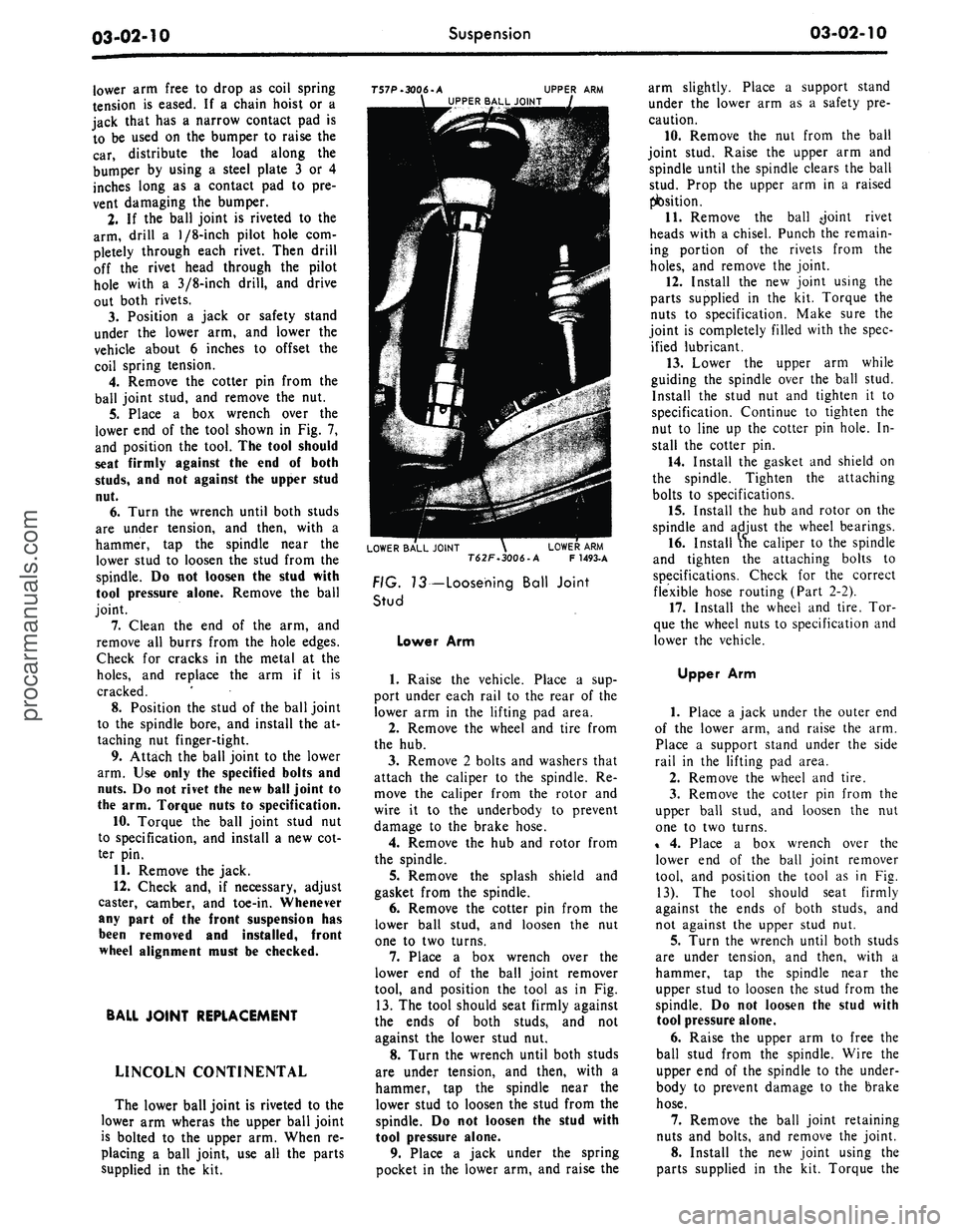
T57P-3006-A
UPPER
ARM
UPPER BALL JOINT
LOWER BALL JOINT
\
LOWER
ARM
T62F.3006-A
F
1493-A
FIG. 13— Loosening Ball Joint
Stud
Lower
Arm
1.
Raise
the
vehicle. Place
a sup-
port under each rail
to the
rear
of
the
lower
arm in the
lifting
pad
area.
2.
Remove
the
wheel
and
tire from
the
hub.
3.
Remove
2
bolts
and
washers that
attach
the
caliper
to the
spindle.
Re-
move
the
caliper from
the
rotor
and
wire
it to the
underbody
to
prevent
damage
to the
brake hose.
4.
Remove
the hub and
rotor from
the spindle.
5.
Remove
the
splash shield
and
gasket from
the
spindle.
6. Remove
the
cotter
pin
from
the
lower ball stud,
and
loosen
the nut
one
to two
turns.
7.
Place
a box
wrench over
the
lower
end of the
ball joint remover
tool,
and
position
the
tool
as in Fig.
13.
The
tool should seat firmly against
the ends
of
both studs,
and not
against
the
lower stud
nut.
8. Turn
the
wrench until both studs
are under tension,
and
then, with
a
hammer,
tap the
spindle near
the
lower stud
to
loosen
the
stud from
the
spindle.
Do not
loosen
the
stud with
tool pressure alone.
9. Place
a
jack under
the
spring
pocket
in the
lower
arm, and
raise
the
arm slightly. Place
a
support stand
under
the
lower
arm as a
safety
pre-
caution.
10.
Remove
the nut
from
the
ball
joint stud. Raise
the
upper
arm and
spindle until
the
spindle clears
the
ball
stud. Prop
the
upper
arm in a
raised
position.
11.
Remove
the
ball -joint rivet
heads with
a
chisel. Punch
the
remain-
ing portion
of the
rivets from
the
holes,
and
remove
the
joint.
12.
Install
the
new
joint using
the
parts supplied
in the kit.
Torque
the
nuts
to
specification. Make sure
the
joint
is
completely filled with
the
spec-
ified lubricant.
13.
Lower
the
upper
arm
while
guiding
the
spindle over
the
ball stud.
Install
the
stud
nut and
tighten
it to
specification. Continue
to
tighten
the
nut
to
line
up the
cotter
pin
hole.
In-
stall
the
cotter
pin.
14.
Install
the
gasket
and
shield
on
the spindle. Tighten
the
attaching
bolts
to
specifications.
15.
Install
the
hub and
rotor
on the
spindle
and
adjust
the
wheel bearings.
16.
Install
the
caliper
to
the
spindle
and tighten
the
attaching bolts
to
specifications. Check
for the
correct
flexible hose routing (Part
2-2).
17.
Install
the
wheel
and
tire.
Tor-
que
the
wheel nuts
to
specification
and
lower
the
vehicle.
Upper
Arm
1.
Place
a
jack under
the
outer
end
of
the
lower
arm,
and
raise
the arm.
Place
a
support stand under
the
side
rail
in the
lifting
pad
area.
2.
Remove
the
wheel
and
tire.
3.
Remove
the
cotter
pin
from
the
upper ball stud,
and
loosen
the nut
one
to two
turns.
%
4.
Place
a box
wrench over
the
lower
end of the
ball joint remover
tool,
and
position
the
tool
as in Fig.
13).
The
tool should seat firmly
against
the
ends
of
both studs,
and
not against
the
upper stud
nut.
5.
Turn
the
wrench until both studs
are under tension,
and
then, with
a
hammer,
tap the
spindle near
the
upper stud
to
loosen
the
stud from
the
spindle.
Do not
loosen
the
stud with
tool pressure alone.
6. Raise
the
upper
arm to
free
the
ball stud from
the
spindle. Wire
the
upper
end
of
the
spindle
to the
under-
body
to
prevent damage
to the
brake
hose.
7.
Remove
the
ball joint retaining
nuts
and
bolts,
and
remove
the
joint.
8. Install
the new
joint using
the
parts supplied
in the kit.
Torque
theprocarmanuals.com
Page 90 of 413

03-02-14
Suspension
03-02-14
FRONT SPRING AND
LOWER ARM
LINCOLN CONTINENTAL
Removal
1.
Raise the vehicle. Place a sup-
port under each underbody side rail to
the rear of the lower arm in the lifting
pad area.
2.
Remove the wheel and tire from
the hub.
3.
Remove 2 bolts and washers that
attach the caliper to the spindle. Re-
move the caliper from the rotor and
wire it to the underbody to prevent
damage to the brake hose.
4.
Remove the hub and rotor from
the spindle.
5.
Loosen the splash shield to pro-
vide clearance at the end of the arm
when it is lowered.
6. Remove the shock absorber.
7.
Disconnect the stabilizing strut
(drag strut) from the lower arm.
8. Disconnect the stabilizer bar
from the suspension bar.
9. Remove the cotter pin from the
slotted nut attaching the lower ball
joint to the end of the spindle boss.
Loosen the nut one to two turns.
10.
Place a box wrench over the
lower end of the ball joint remover
tool, and position the tool as in Fig.
13.
The tool should seat firmly against
the ends of both studs, and not
against the lower stud nut.
11.
Turn the wrench until both
studs are under tension, then, tap the
spindle with a hammer near the lower
stud to loosen it from the spindle. Do
not loosen the stud with tool pressure
alone.
12.
Place a jack under the outer
end of the lower arm and raise the
arm several inches.
13.
Install the spring compressor
Tool 5310-A (Fig. 23) inside the
spring with the jaws of the tool
toward the center of the vehicle.
14.
Remove the nut from the ball
joint stud. Lower the jack until the
spindle and spring are free, and re-
move the spring and insulators.
15.
Remove the lower arm- to-
crossmember nut, bolt, washers, and
spacer, then remove the arm.
Installation
1.
Connect the inner end of the
lower arm to the underbody
crossmember. Do not tighten the at-
taching nut at this time. Refer to Fig.
22.
Basic Tool Adapter F 1288-B
FIG. 20—Spring Compressor Tool Installed—Upper View—Typical
DETAIL NO 3 T63P-5310-A DETAIL NO.4
DETAIL
NO.
I
21 —Compressing Spring—Lower View—Montego, Falcon
and Fairlaneprocarmanuals.com
Page 92 of 413
03-02-16
Suspension
03-02-16
2.
Place a jack under the outer end
of the arm.
3.
Tape the upper and lower spring
insulators to the spring.
4.
Compress the coil spring with
Tool 5310-A (Fig. 23) and place the
spring and insulators in position. Be
sure both ends of the spring are prop-
erly seated, and raise the arm. Guide
the spindle boss over the ball joint
stud.
5.
Install the ball joint stud retain-
ing nut and torque it to specification.
Continue tightening the nut to line up
the cotter pin hole. Install a new cot-
ter pin.
6. Connect the stabilizer bar to the
lower arm. Torque the nut to specifi-
cation.
7.
Connect the drag strut to the
lower arm. Torque the nuts to specifi-
cation.
8. Install the shock absorber.
9. Tighten the splash shield attach-
ing bolts to specifications.
10.
Install the hub and rotor on the
spindle and adjust the wheel bearings.
11.
Install the caliper to the spindle
and tighten the attaching bolts to
specifications. Check for the correct
flexible hose routing (Part 2-2).
12.
Install the wheel and tire on the
hub.
Torque the wheel lug nuts to
specifications and remove the support
stands.
13.
With the front end weight of
the car on the wheels, torque the
lower arm-to-crossmember bolt at-
taching nut to specification.
FRONT SUSPENSION
LOWER ARM
FORD, MERCURY,
METEOR, THUNDERBIRD,
CONTINENTAL MARK III
Removal
1.
Raise the front of the vehicle and
position safety stands under both sides
of the frame just back of the lower
arms.
2.
Remove the hub cap or wheel
cover.
3.
If equipped with drum type
brakes—Remove the wheel and tire
and brake drum as an assembly. Re-
move the brake backing plate attach-
ing bolts and remove the backing
plate from the spindle. Wire the back-
ing plate to the underbody to prevent
damage to the brake hose.
4.
If equipped with disc brakes-
—Remove the wheel and tire from the
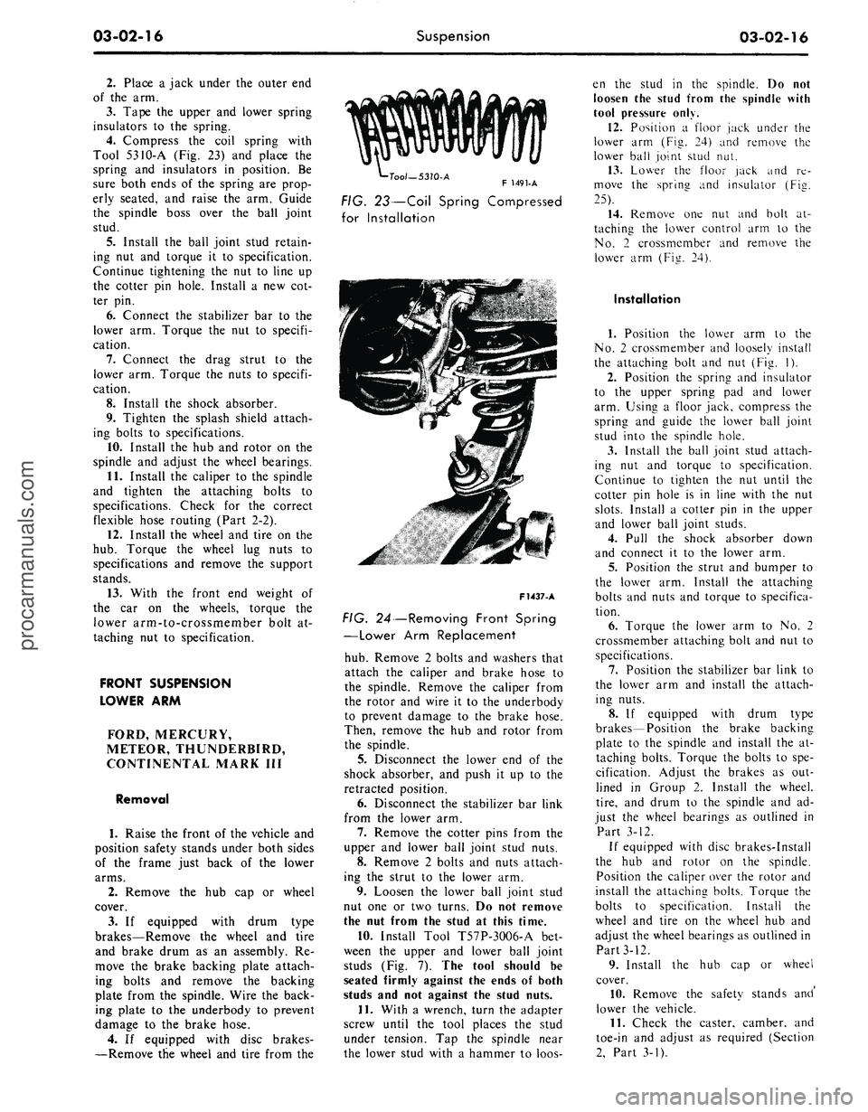
•Tool—5310-A
F 1491-A
FIG. 23—Coil Spring Compressed
for Installation
F1437-A
FIG. 24—Removing Front Spring
—Lower Arm Replacement
hub.
Remove 2 bolts and washers that
attach the caliper and brake hose to
the spindle. Remove the caliper from
the rotor and wire it to the underbody
to prevent damage to the brake hose.
Then, remove the hub and rotor from
the spindle.
5.
Disconnect the lower end of the
shock absorber, and push it up to the
retracted position.
6. Disconnect the stabilizer bar link
from the lower arm.
7.
Remove the cotter pins from the
upper and lower ball joint stud nuts.
8. Remove 2 bolts and nuts attach-
ing the strut to the lower arm.
9. Loosen the lower ball joint stud
nut one or two turns. Do not remove
the nut from the stud at this time.
10.
Install Tool T57P-3OO6-A bet-
ween the upper and lower ball joint
studs (Fig. 7). The tool should be
seated firmly against the ends of both
studs and not against the stud nuts.
11.
With a wrench, turn the adapter
screw until the tool places the stud
under tension. Tap the spindle near
the lower stud with a hammer to loos-
en the stud in the spindle. Do not
loosen the stud from the spindle with
tool pressure only.
12.
Position a floor jack under the
lower arm (Fig. 24) and remove the
lower ball joint stud nut.
13.
Lower the floor jack and re-
move the sprina and insulator (Fie.
25).
14.
Remove one nut and bolt at-
taching the lower control arm to the
No.
2 crossmember and remove the
lower arm (Fig. 24).
Installation
1.
Position the lower arm to the
No.
2 crossmember and loosely install
the attaching bolt and nut (Fig. 1).
2.
Position the spring and insulator
to the upper spring pad and lower
arm. Using a floor jack, compress the
spring and guide the lower ball joint
stud into the spindle hole.
3.
Install the ball joint stud attach-
ing nut and torque to specification.
Continue to tighten the nut until the
cotter pin hole is in line with the nut
slots.
Install a cotter pin in the upper
and lower ball joint studs.
4.
Pull the shock absorber down
and connect it to the lower arm.
5.
Position the strut and bumper to
the lower arm. Install the attaching
bolts and nuts and torque to specifica-
tion.
6. Torque the lower arm to No. 2
crossmember attaching bolt and nut to
specifications.
7.
Position the stabilizer bar link to
the lower arm and install the attach-
ing nuts.
8. If equipped with drum type
brakes—Position the brake backing
plate to the spindle and install the at-
taching bolts. Torque the bolts to spe-
cification. Adjust the brakes as out-
lined in Group 2. Install the wheel,
tire,
and drum to the spindle and ad-
just the wheel bearings as outlined in
Part 3-12.
If equipped with disc brakes-Install
the hub and rotor on the spindle.
Position the caliper over the rotor and
install the attaching bolts. Torque the
bolts to specification. Install the
wheel and tire on the wheel hub and
adjust the wheel bearings as outlined in
Part 3-12.
9. Install the hub cap or wheel
cover.
10.
Remove the safety stands and'
lower the vehicle.
11.
Check the caster, camber, and
toe-in and adjust as required (Section
2,
Part 3-1).procarmanuals.com
Page 95 of 413
03-02-19
Suspension
03-02-19
6. Raise the upper arm to free the
ball joint stud from the spindle. Wire
the upper end of the spindle to the un-
derbody to prevent damage to the
brake hose.
7.
Mark the position of the upper
arm shaft on the underbody member
to facilitate making caster and camber
adjustments after installation of the
upper arm.
8. Remove the suspension upper
arm-to-underbody attaching bolts,
lock washers, and attaching nuts.
Then, remove the upper arm.
Installation
1.
Position the upper arm shaft on
the underbody member. Line up the
shaft with the marks made before re-
moval of the arm.
2.
Install the attaching bolts and
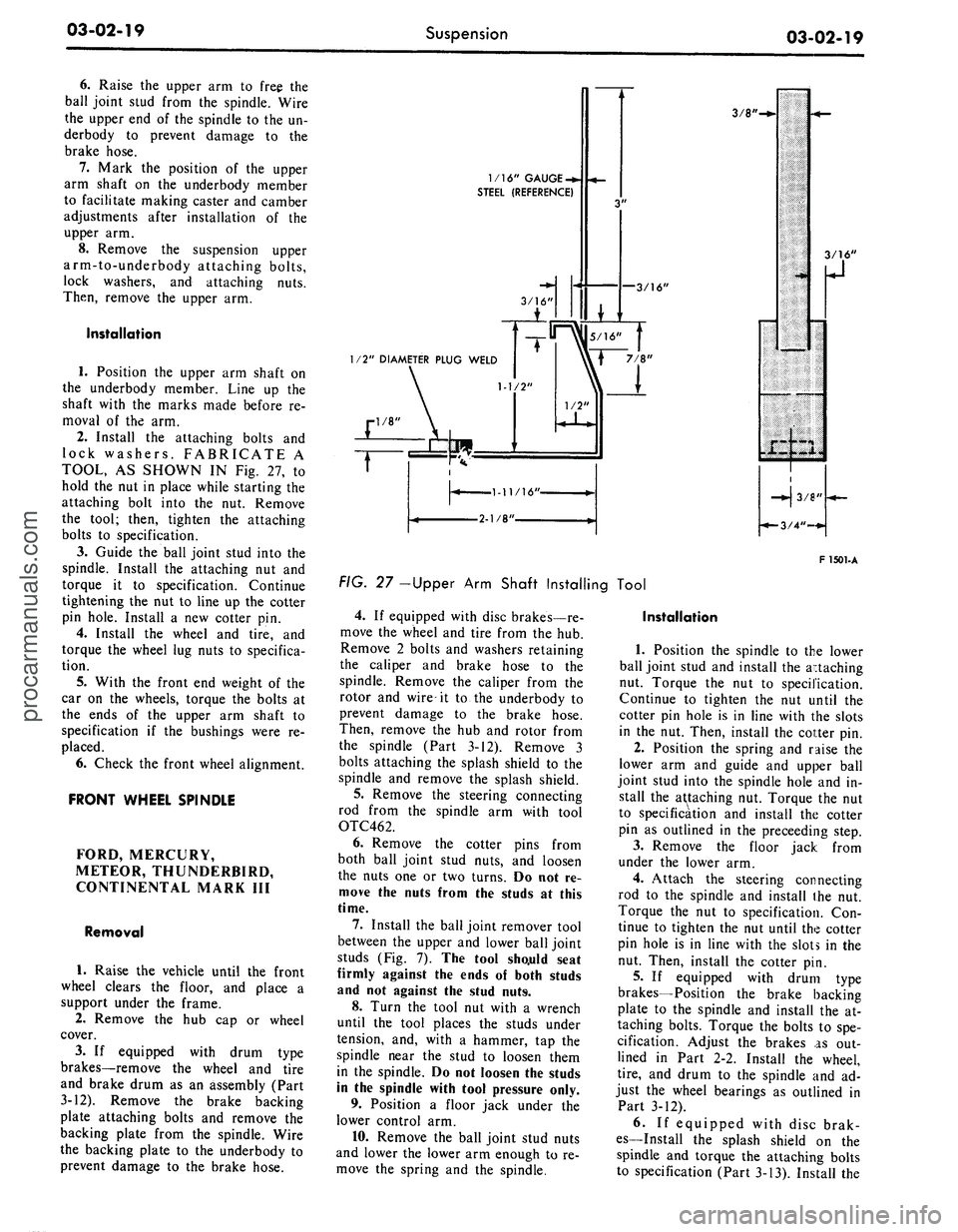
lock washers. FABRICATE A
TOOL, AS SHOWN IN Fig. 27, to
hold the nut in place while starting the
attaching bolt into the nut. Remove
the tool; then, tighten the attaching
bolts to specification.
3.
Guide the ball joint stud into the
spindle. Install the attaching nut and
torque it to specification. Continue
tightening the nut to line up the cotter
pin hole. Install a new cotter pin.
4.
Install the wheel and tire, and
torque the wheel lug nuts to specifica-
tion.
5.
With the front end weight of the
car on the wheels, torque the bolts at
the ends of the upper arm shaft to
specification if the bushings were re-
placed.
6. Check the front wheel alignment.
FRONT WHEEL SPINDLE
FORD, MERCURY,
METEOR, THUNDERBIRD,
CONTINENTAL MARK III
Removal
1.
Raise the vehicle until the front
wheel clears the floor, and place a
support under the frame.
2.
Remove the hub cap or wheel
cover.
3.
If equipped with drum type
brakes—remove the wheel and tire
and brake drum as an assembly (Part
3-12). Remove the brake backing
plate attaching bolts and remove the
backing plate from the spindle. Wire
the backing plate to the underbody to
prevent damage to the brake hose.
1/16" GAUGE
-*.
STEEL (REFERENCE)
—3/16'
3/8'
1/2" DIAMETER PLUG WELD
F 1501-A
FIG. 27 -Upper Arm Shaft Installing Tool
4.
If equipped with disc brakes—re-
move the wheel and tire from the hub.
Remove 2 bolts and washers retaining
the caliper and brake hose to the
spindle. Remove the caliper from the
rotor and wire it to the underbody to
prevent damage to the brake hose.
Then, remove the hub and rotor from
the spindle (Part 3-12). Remove 3
bolts attaching the splash shield to the
spindle and remove the splash shield.
5.
Remove the steering connecting
rod from the spindle arm with tool
OTC462.
6. Remove the cotter pins from
both ball joint stud nuts, and loosen
the nuts one or two turns. Do not re-
move the nuts from the studs at this
time.
7.
Install the ball joint remover tool
between the upper and lower ball joint
studs (Fig. 7). The tool sho.uld seat
firmly against the ends of both studs
and not against the stud nuts.
8. Turn the tool nut with a wrench
until the tool places the studs under
tension, and, with a hammer, tap the
spindle near the stud to loosen them
in the spindle. Do not loosen the studs
in the spindle with tool pressure only.
9. Position a floor jack under the
lower control arm.
10.
Remove the ball joint stud nuts
and lower the lower arm enough to re-
move the spring and the spindle.
Installation
1.
Position the spindle to the lower
ball joint stud and install the attaching
nut. Torque the nut to specification.
Continue to tighten the nut until the
cotter pin hole is in line with the slots
in the nut. Then, install the cotter pin.
2.
Position the spring and raise the
lower arm and guide and upper ball
joint stud into the spindle hole and in-
stall the attaching nut. Torque the nut
to specification and install the cotter
pin as outlined in the preceeding step.
3.
Remove the floor jack from
under the lower arm.
4.
Attach the steering connecting
rod to the spindle and install the nut.
Torque the nut to specification. Con-
tinue to tighten the nut until the cotter
pin hole is in line with the slots in the
nut. Then, install the cotter pin.
5.
If equipped with drum type
brakes—Position the brake backing
plate to the spindle and install the at-
taching bolts. Torque the bolts to spe-
cification. Adjust the brakes as out-
lined in Part 2-2. Install the wheel,
tire,
and drum to the spindle and ad-
just the wheel bearings as outlined in
Part 3-12).
6. If equipped with disc brak-
es—Install the splash shield on the
spindle and torque the attaching bolts
to specification (Part 3-13). Install theprocarmanuals.com
Page 96 of 413

03-02-20
Suspension
03-02-20
hub and rotor on the spindle. Position
the caliper over the rotor and install
the attaching bolts. Torque the bolts
to specification (Part 3-13). Install the
wheel and tire on the hub and adjust
the wheel bearings as outlined in Part
3-12 .
7.
Install the hub cap or wheel
cover. Then, remove the support stand
and lower the vehicle.
8. Check caster, camber, and toe-in
(Part 3-1) and adjust as necessary.
COUGAR, FAIRLANE,
FALCON, MONTEGO,
MUSTANG
Drum Brakes
Removal
1.
Position a support between the
upper arm and frame as shown in
Figs.
8 and 9; then, raise the vehicle
and position safety stands.
2.
Remove the hub cap or wheel
cover.
3.
Remove the grease cap from the
hub;
then, remove the adjusting nut,
washer, and outer bearing cone and
roller assembly.
4.
Pull the wheel, hub, and drum
assembly off the wheel spindle.
5.
Remove the brake backing plate
from the spindle. Support the plate to
prevent damage to the brake hose.
6. Disconnect the spindle connect-
ing rod end from the spindle arm
using Tool 3290-C.
7.
Remove the cotter pins from
both ball joint stud nuts, and loosen
the nuts one or two turns. Do not re-
move the nuts from the studs at this
time.
8. Position the ball joint remover
tool between the upper and lower ball
joint studs (Fig. 10). The tool should
seat firmly against the ends of both
studs and not against the stud nuts.
9. Turn the tool with a wrench until
the tool places the studs under consid-
erable tension, and, with a hammer,
hit the spindle smartly near the studs
to break them loose in the spindle. Do
not loosen the studs in the spindle
with tool pressure alone.
10.
Remove the stud nuts and re-
move the spindle from both studs.
Installation
1.
Position the spindle on the lower
ball joint stud and install the stud nut
(Fig. 25).
2.
Raise the lower suspension arm
and guide the upper ball joint stud
into the spindle. Install the stud nut.
3.
Torque the upper stud nut and
then the lower stud nut to specifica-
tion. Continue to tighten both nuts
until the cotter pin holes and slots line
up.
Install new cotter pins.
4.
Connect the spindle connecting
rod end to the spindle arm.
5.
Install the brake backing plate
on the spindle, and torque the bolts to
specification.
6. Install the wntel and drum and
adjust the wheel bearing (Part 3-12).
7.
Remove the safety stands, and
lower the vehicle.
8. Remove the support from be-
tween the upper arm and frame.
9. Check and, if necessary, adjust
caster, camber, and toe-in.
Disc Brakes
Removal
1.
Remove the hub cap or wheel
cover, and remove the wheel and tire
from the hub.
2.
Remove two bolts attaching the
caliper to the spindle. Remove the cal-
iper from the rotor and wire it to the
underbody to prevent damage to the
brake hose.
3.
Remove the grease cap from the
hub,
then, remove the adjusting nut,
washer, and outer bearing cone and
roller assembly.
4.
Pull the hub and rotor assembly
off the wheel spindle.
5.
Remove the three caliper shield
attaching bolts and remove the shield.
6. Disconnect the spindle connect-
ing rod end from the spindle arm
using Tool-3290-C.
7.
Remove the cotter pins from
both ball joint stud nuts, and loosen
the nuts one or two turns. Do not re-
move the nuts from the studs at this
time.
8. Position the ball joint remover
tool between the upper and lower ball
joint studs (Fig. 10). The tool should
seat firmly against the ends of both
studs and not against the stud nuts.
9. Turn the tool with a wrench until
the tool places the studs under consid-
erable tension, and, with a hammer,
hit the spindle smartly near the studs
to break them loose in the spindle. Do
not loosen the studs in the spindle
with tool pressure alone.
10.
Position a floor jack under the
lower suspension arm.
11.
Remove the upper and lower
ball joint stud nuts; lower the jack
and remove the spindle.
Installation
1.
Position the spindle on the lower
ball joint stud and install the stud nut
(Fig. 25). Torque the nut to specifica-
tion and install the cotter pin.
2.
Raise the lower suspension arm,
and guide the upper ball joint stud
into the spindle. Install the stud nut.
3.
Torque the nut to specifications
and install the cotter pin. Then, re-
move the floor jack.
4.
Connect the spindle connecting
rod end to the spindle arm and install
the attaching nut. Torque the nut to
specification and install the cotter pin.
5.
Position the caliper splash shield
to the spindle and install the attaching
bolts and nuts. Torque the nuts and
bolts to specification.
6. Install the hub and rotor on the
spindle.
7.
Position the caliper to the rotor
and spindle and install the attaching
bolts.
Torque the bolts to specification
and install the safety wire.
8. Install the wheel and tire on the
hub and adjust the wheel bearing
(Part 3-12).
9. Install the hub cap or wheel
cover.
10.
Before driving the vehicle,
pump the brake pedal several times to
obtain normal brake lining-to-rotor
clearance and restore normal brake
pedal travel.
LINCOLN CONTINENTAL
Removal
1.
Raise the vehicle. Place a sup-
port under each side rail to the rear of
the lower arm in the lifting pad area.
2.
Remove the wheel and tire from
the hub.
3.
Remove 2 bolts and washers that
attach the caliper to the spindle. Re-
move the caliper from the rotor and
wire it to the underbody to prevent
damage to the brake hose.
4.
Remove the hub and rotor from
the spindle.
5.
Remove the splash shield and
gasket from the spindle.
6. Disconnect the spindle arm con-
necting rod from the spindle arm with
Tool 3290-C. See Fig. 23.
7.
Remove the cotter pins from
both ball joint stud nuts. Loosen the
nuts one to two turns.procarmanuals.com
Page 172 of 413
03-12-01
Wheels
And
Tires
03-12-01
PART
3-12
Wheels
And
Tires
COMPONENT INDEX
FRONT
HUB AND
DRUM ASSEMBLY
Removal
and
Installation
FRONT
HUB AND
ROTOR ASSEMBLY
Removal
and
Installation
FRONT WHEEL ASSEMBLY DESCRIPTION
FRONT WHEEL BEARING ADJUSTMENT
FRONT WHEEL GREASE SEAL
AND
BEARING
Removal, Installation, Repacking
HOISTING INSTRUCTIONS
LIFE GUARD TIRE
Balancing
Correcting Vibration
and
Shake
Description
Repairs
REAR WHEEL ASSEMBLY DESCRIPTION
WHEELS AND TIRES (Conventional)
Removal
and
Installation
MODEL APPLICATION
All
Models
12-07
12-07
12-01
12-02
12-05
12-02
12-01
12-03
Ford
N/A
N/A
N/A
N/A
Mercury
N/A
N/A
N/A
N/A
Meteor
N/A
N/A
N/A
N/A
Cougar
N/A
N/A
N/A
N/A
Fairlane
N/A
N/A
N/A
N/A
Falcon
N/A
N/A
N/A
N/A
Montego
N/A
N/A
N/A
N/A
Mustang
N/A
N/A
N/A
N/A
Lincoln-
Continental
12-03
12-03
12-02
12-08
Thunderbird
12-03
12-03
12-02
12-08
Continental-
Mark
III
12-03
12-03
12-02
12-08
A page number indicates that
the
item
is for the
vehicle listed
at the
head
of the
column.
N/A indicates that
the
item
is not
applicable
to the
vehicle listed.
DESCRIPTION
FRONT WHEEL ASSEMBLY
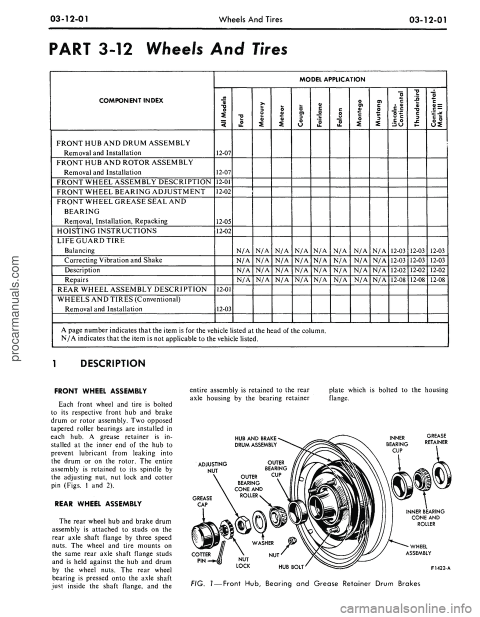
Each front wheel
and
tire
is
bolted
to
its
respective front
hub and
brake
drum
or
rotor assembly.
Two
opposed
tapered roller bearings
are
installed
in
each
hub. A
grease retainer
is in-
stalled
at the
inner
end of the hub to
prevent lubricant from leaking into
the drum
or on the
rotor.
The
entire
assembly
is
retained
to its
spindle
by
the adjusting
nut, nut
lock
and
cotter
pin (Figs.
1 and 2).
REAR WHEEL ASSEMBLY
The rear wheel
hub and
brake drum
assembly
is
attached
to
studs
on the
rear axle shaft flange
by
three speed
nuts.
The
wheel
and
tire mounts
on
the same rear axle shaft flange studs
and
is
held against
the hub and
drum
by
the
wheel nuts.
The
rear wheel
bearing
is
pressed onto
the
axle shaft
just inside
the
shaft flange,
and the
entire assembly
is
retained
to the
rear
axle housing
by the
bearing retainer
HUB
AND
BRAKE
DRUM
ASSEMBLY
plate which
is
bolted
to the
housing
flange.
ADJUSTING
NUT
GREASE
CAP
OUTER
BEARING
OUTER
CUP
BEARING
CONE
AND
ROLLER
NUT
INNER BEARING
CONE
AND
ROLLER
WHEEL
ASSEMBLY
HUB
BOLT'
^£=3^
F1422-A
FIG.
1
—
Front
Hub,
Bearing
and
Grease Retainer Drum Brakes
procarmanuals.com
Page 173 of 413

03-12-02
Wheels
And
Tires
03-12-02
LIFE GUARD TIRE
The Goodyear Power Cushion Tire
(available
on
Thunderbird, Lincoln
and Continental Mark
III
models)
fit-
ted with
the
Life Guard Safety Spare
provides
a
tire within
a
tire with
two
separate
air
chambers
(Fig.
3). If the
outer tire casing should
be
punctured
or otherwise damaged causing
it to go
flat,
the
Life Guard Safety Spare will
carry
the
load
of the
vehicle
and
will
allow driving
at
speeds
up to 40 mph
with good control
up to a
distance
of
40 miles.
A
Safety-Signal built into
the Life Guard tread produces
a
lope
or vibration indicating
the
outer tire
has lost pressure.
HUB AND ROTOR
ASSEMBLY
INNER
BEARING
CUP
GREASE
RETAINER
ADJUSTING
NUT
OUTER
BEARING
CONE
AND
ROLLER
INNER BEARING
CONE
AND
ROLLER
WHEEL
ASSEMBLY
F1416-A
F- 1380 •
A
FIG. 2—Front
Hub and
Rotor Bearing
and
Grease
Retainer Disc Brakes—Typical
FIG. 3—Life Guard Safety
Tire—Sectional View
IN-VEHICLE ADJUSTMENTS AND REPAIRS
HOISTING INSTRUCTIONS
Damage
to
steering linkage compo-
nents
and
front suspension struts
may
occur
if
care
is
not
exercised when
po-
sitioning
the
hoist adapters
of 2
post
hoists prior
to
lifting
the
vehicle.
If
a 2
post hoist
is
used
to
lift
the
vehicle, place
the
adapters under
the
lower arms
or
the No. 1
crossmember.
Do
not
allow
the
adapters
to
contact
steering linkage.
If the
adapters
are
placed under
the
crossmember,
a
piece
of wood (2x4x16 inches) should
be
placed
on the
hoist channel between
the adapters. This will prevent
the
adapters from damaging
the
front
sus-
pension struts.
FRONT WHEEL BEARING
ADJUSTMENT
The front wheel bearings should
be
adjusted
if the
wheel
is
loose
on the
spindle
or if the
wheel does
not
rotate
freely.
The
following procedures will
bring
the
bearing adjustment
to
speci-
fication.
DRUM BRAKES
1.
Raise
the
vehicle until
the
wheel
and tire clear
the
floor.
2.
Pry off the hub cap or
wheel
cover
and
remove
the
grease
cap (Fig.
1) from
the hu6.
3.
Wipe
the
excess grease from
the
end
of the
spindle,
and
remove
the
cotter
pin and nut
lock.
4.
While rotating
the
wheel,
hub,
and drum assembly, torque
the
adjust-
ing
nut to 17-25
ft-lbs
to
seat
the
bearings
(Fig.
4).
5.
Locate
the nut
lock
on the ad-
justing
nut so
that
the
castellations
on
the lock
are
aligned with
the
cotter
pin hole
in the
spindle.
6. Using
a 1
1/8-inch
box
wrench,
WITH WHEEL ROTATING
TORQUE ADJUSTING
NUT
TO 17-25 FT. LBS.
BACK ADJUSTING
NUT
OFF
1/2
TURN
back
off the
adjusting
nut one
half
turn. Retighten
the
adjusting
nut to
10-15 in-lbs with
a
torque wrench
or
finger tight.
7.
Position
the
lock
on the
adjust-
ing
nut and
install
a new
cotter
pin.
Bend
the
ends
of
the
cotter
pin
around
the castellated flange
of the nut
lock.
8. Check
the
front wheel rotation.
If
the
wheel rotates properly, install
the grease
cap and the hub cap or
wheel cover.
If the
wheel still rotates
roughly
or
noisily, clean, inspect
or
replace
the
bearings
and
cups
as re-
quired.
TIGHTEN ADJUSTING
NUT
TO
10-15 IN.-LBS.
INSTALL THE LOCK
AND
A
NEW COTTER
PIN
F1417-A
FIG. 4— Front Wheel Bearing Adjustmentprocarmanuals.com
Page 174 of 413

03-12-03
Wheels And Tires
03-12-03
DISC BRAKES
1.
Raise the vehicle until the wheel
and tire clear the floor.
2.
Pry off the wheel cover and re-
move the grease cap (Fig. 2) from the
hub.
3.
Wipe the excess grease from the
end of the spindle, and remove the ad-
justing nut cotter pin and nut lock.
4.
Loosen the bearing adjusting nut
three turns. Then, rock the wheel,
hub,
and rotor assembly in and out
several times to push the shoe and lin-
ings away from the rotor.
5.
While rotating the wheel, hub,
and rotor assembly, torque the adjust-
ing nut to 17-25 ft-lbs to seat the
bearings (Fig. 4).
6. Back the adjusting nut off one
half turn. Then, retighten the adjust-
ing nut to 10-15 in-lbs with a torque
wrench or finger tight.
7.
Locate the nut lock on the ad-
justing nut so that the castellations on
the lock are aligned with the cotter
pin hole in the spindle.
8. Install a new cotter pin, and
bend the ends of the cotter pin around
the castellated flange of the nut lock.
9. Check the front wheel rotation.
If the wheel rotates properly, install
the grease cap and the hub cap or
wheel cover. If the wheel still rotates
roughly or noisily, clean or replace the
bearings and cups as required.
10.
Before driving the vehicle,
pump the brake pedal several times to
obtain normal brake lining to rotor
clearance and restore normal brake
pedal travel.
BALANCING LIFE
GUARD TIRE
Tires fitted with the Life Guard
Safety Spare are balanced in the same
manner as conventional tires. If an ex-
cessive out of balance condition exists
the following procedure can be used to
correct the condition:
1.
Remove the core housing and de-
flate both air chambers.
2.
Install the core housing.
3.
Unseat the beads of tire with the
bead breakers away from the valve
stem as shown in Fig. 5.
F 1383
FIG. 5—Breaking Top Bead of
Tire From Wheel Rim
4.
Rotate tire casing 90 degrees on
the wheel rim.
5.
Rotate the tire casing back and
forth on the rim to center the valve.
6. Inflate both chambers of the tire
following steps 13 through 15 of the
Tire Installation procedure.
7.
Balance the tire in the normal
manner.
CORRECTING VIBRATION
AND SHAKE-
LIFE GUARD TIRE
The condition of excessive vibration
and shake is generally the result of an
incorrect pressure relationship between
the inner and outer air chambers that
may cause the life guard to shift posi-
tion within the tire. The following
procedure should be used to correct
vibration and shake conditions:
1.
Check pressure of the inner and
outer air chambers on all four tires.
2.
If the inner chamber has at least
five psi more pressure than the outer
chamber the pressures should be ad-
justed and the tires rebalanced if nec-
essary.
3.
If the pressures of the inner and
outer air chambers are equal the Air
Container is leaking. To repair the
leaking air container the recommend-
ed procedures for the removal, repair
of air container, mounting, and bal-
ancing should be followed.
REMOVAL AND INSTALLATION
HOISTING INSTRUCTIONS
Damage to steering linkage compo-
nents and front suspension struts may
occur if care is not exercised when po-
sitioning the hoist adapters of 2 post
hoists prior to lifting the vehicle.
If a 2 post hoist is used to lift the
vehicle, place the adapters under the
lower arms or the No. 1 crossmember.
Do not allow the adapters to contact
the steering linkage. If the adapters
are placed under the crossmember, a
piece of wood (2x4x16 inches) should
be placed on the hoist channel be-
tween the adapters. This will prevent
the adapters from damaging the front
suspension struts.
WHEELS AND TIRES
WHEEL AND TIRE
REMOVAL
1.
Pry off the wheel hub cap or
wheel cover. Loosen but do not re-
move the wheel hub nuts.
2.
Raise the vehicle until the
wheel and tire clear the floor.
3.
Remove the wheel hub nuts
from the bolts, and pull the wheel
and tire from hub and drum.
F1424-
A
FIG.
6—Bead
Loosening Tool
REMOVING CONVENTIONAL
TIRE FROM WHEEL
The tire can be demounted on a
mounting machine. Be sure that the
outer side of the wheel is positioned
downward. If tire irons are used, fol-
low the procedure given here.
1.
Remove the valve cap and core,
and deflate the tire completely.
2.
With a bead loosening tool,
break loose the tire side walls from
the wheel (Fig. 6).
3.
Position the outer side of the
wheel downward, and insert two tire
irons about eight inches apart between
the tire inner bead and the back side
of the wheel rim. Use only tire irons
with rounded edges or irons designed
for removing tubeless tires.
4.
Leave one tire iron in position,
and pry the rest of the bead over the
rim with the other iron. Take small
bites with the iron around the tire inprocarmanuals.com