Page 110 of 252

ENGINE
ELECTRICAL
SYSTEM
105
VOLTAGE
REGULATOR
REMOVAL
To
remove
the
voltage
regulator
dISconnect
the
6
way
multIple
electrIcal
COlInector
and
the
screws
holdmg
the
regulator
to
the
SIde
wall
lJ
R
ftl5
C
Wt
Str
Ii
DISTRIBUTOR
W
I
vE
Dlstnbutors
used
on
models
covered
m
this
manual
are
SImilar
except
that
some
have
a
dual
contact
pomt
system
rather
than
a
single
contact
system
The
dual
pomt
system
applies
to
1970
and
newer
models
eqUIpped
With
the
exhaust
and
evaporatIve
ermsslOn
control
deVIce
The
pomts
are
placed
m
parallel
In
the
circuIt
so
that
there
IS
a
pqase
dIfference
In
their
opera
tIon
Phase
dlfference
IS
5
degrees
on
1970
19
71
models
and
31h
degrees
on
1972
models
This
can
be
adjusted
With
the
adjustIng
screw
on
what
IS
called
the
retarded
breaker
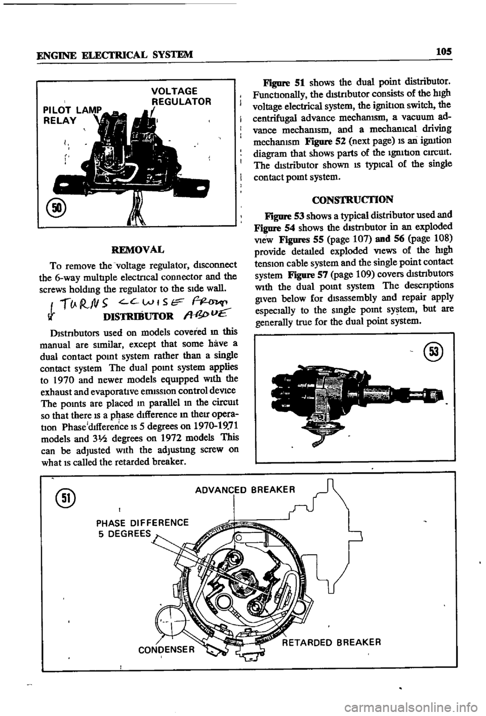
Figure
51
shows
the
dual
point
distributor
FunctIonally
the
dIStnbutor
consists
of
the
hIgh
voltage
electrical
system
the
ignitIon
switch
the
centrifugal
advance
mechanISm
a
vacuum
ad
vance
mechanIsm
and
a
mechanIcal
driving
mechanISm
Figure
52
next
page
IS
an
ignItion
diagram
that
shows
parts
of
the
IgnItIon
CIrCUIt
The
dIstributor
shown
IS
typIcal
of
the
single
contact
pomt
system
CONSTRUCTION
Figure
53
shows
a
typical
distributor
used
and
Figure
54
shows
the
dIStnbutor
in
an
exploded
VIeW
Figures
55
page
107
and
56
page
108
provide
detaIled
exploded
VIews
of
the
lugh
tenSIon
cable
system
and
the
single
point
contact
system
Figure
57
page
109
covers
dIStrIbutors
With
the
dual
pOInt
system
The
descnptions
given
below
for
dIsassembly
and
repair
apply
espeCIally
to
the
smgle
pOInt
system
but
are
generally
true
for
the
dual
point
system
@
@
ADVANCED
BREAKER
PHASE
DIFFERENCE
5
DEGREES
Page 111 of 252
106
CHAPTER
NINE
@
Igmtlon
switch
IgnItion
plug
engine
Condenser
IgnItIon
cod
@
II
9
ft
O
CHECKING
AND
ADJUSTMENT
foreIgn
matenal
or
cracks
Qean
the
cap
thor
oughly
Replace
it
If
cracks
are
found
Inspect
the
hIgh
tensIon
cables
to
see
that
all
connectIons
are
firmly
made
and
that
the
cables
are
not
cracked
Replace
any
defective
cables
Do
not
try
to
tape
or
mend
them
Cap
and
Rotor
Head
The
cap
and
the
rotor
head
must
always
be
kept
clean
to
prevent
lugh
voltage
leaks
Inspect
the
cap
penod1cally
for
SIgnS
of
carbon
bwldup
Page 112 of 252
24
21
TO
oto
25
1
17
18
19
o
15
16
20
@
1
IgnItIon
coIl
2
Ignlllon
COIl
resls
Ol
3
p
II
lS
sere
ll
4
spnng
lles1
Br
5
PlaIn
wesner
6
illstl
OUtor
assembly
1
illstllbu
Ol
sUP
rt
II
sere
ll
9
spnng
wesner
10
0
ling
11
Ills
nbutor
gasket
12
llolt
13
VaCUum
control
tube
14
Vecuum
tube
grommet
IS
spar
plug
IIeslIer
1
sperll
plug
11
111gb
tenSIon
cable
18
IIlglllenSIOn
cable
19
lI
gll
tensIon
cable
20
IIlgII
tensIon
cable
ii
lIlgII
tenSion
cable
22
Ceble
older
23
Cable
c1emp
24
cable
clempllOlder
25
Ceble
clemp
J
Page 116 of 252

ENGINE
ELECTRICAL
SYSTEM
111
@
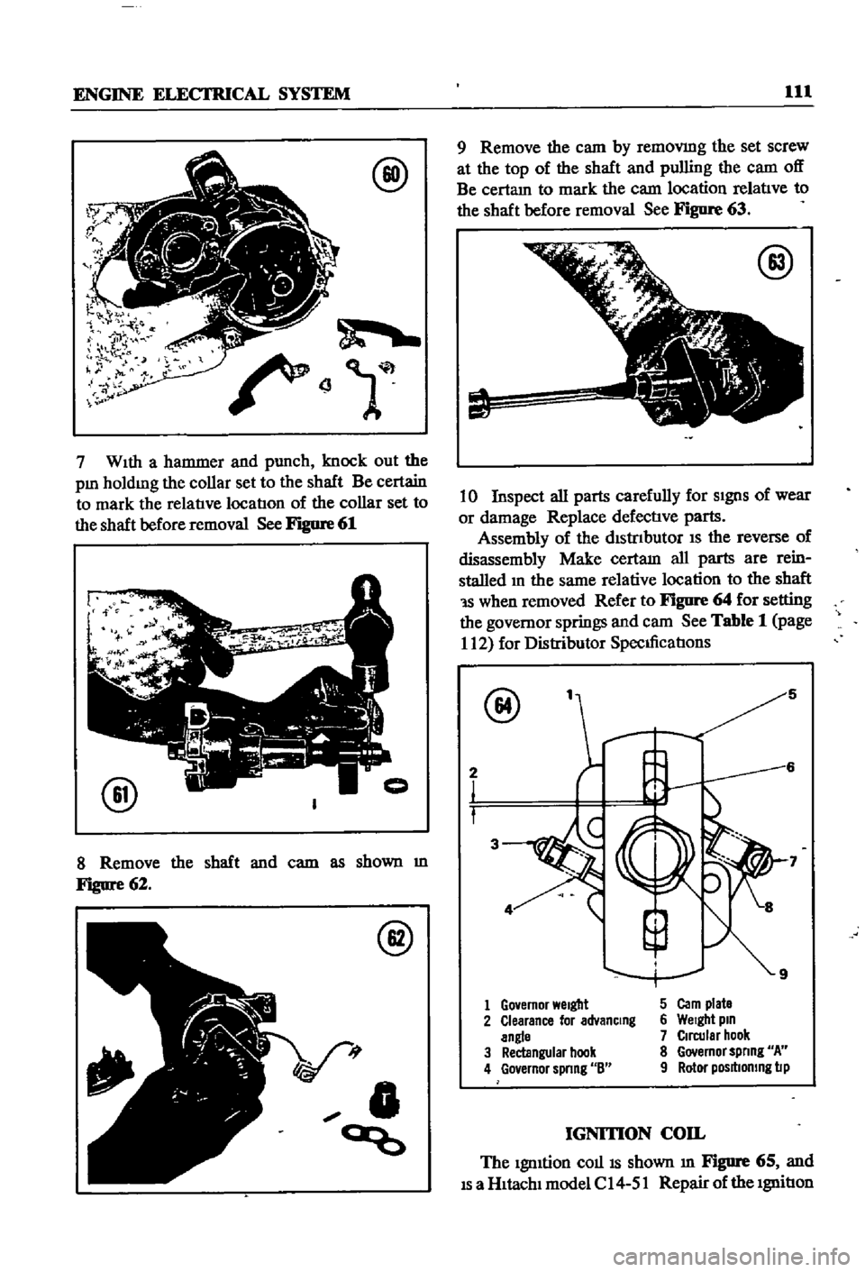
7
WIth
a
hammer
and
punch
knock
out
the
pm
holdmg
the
collar
set
to
the
shaft
Be
certain
to
mark
the
relatIve
locatIon
of
the
collar
set
to
the
shaft
before
removal
See
Figure
61
@
8
Remove
the
shaft
and
cam
as
shown
m
Figure
62
@
V
t
0
ao
9
Remove
the
cam
by
removmg
the
set
screw
at
the
top
of
the
shaft
and
pulling
the
cam
off
Be
certam
to
mark
the
cam
location
relatIve
to
the
shaft
before
removal
See
Figure
63
@
10
Inspect
all
parts
carefully
for
SIgnS
of
wear
or
damage
Replace
defectIve
parts
Assembly
of
the
dIStrIbutor
IS
the
reverse
of
disassembly
Make
certam
all
parts
are
rein
stalled
m
the
same
relative
location
to
the
shaft
1S
when
removed
Refer
to
Figure
64
for
setting
the
governor
springs
and
cam
See
Table
1
page
112
for
Distributor
SpecIficatIons
@
5
2
3
1
Go
emor
Welgbt
5
Carn
plate
2
Clearance
lor
advanCing
6
Welgbt
pin
angle
7
Circular
hook
3
Rectangular
hook
8
Governor
spnng
A
4
Go
ernor
spnng
8
9
Rotor
posltlomng
lip
IGNITION
COIL
The
IgnItion
COllIS
shown
m
Figure
65
and
IS
a
HItachI
model
C
14
51
Repair
of
the
IgnitIon
Page 118 of 252

ENGINE
ELECI
RICAL
SYSTEM
113
i
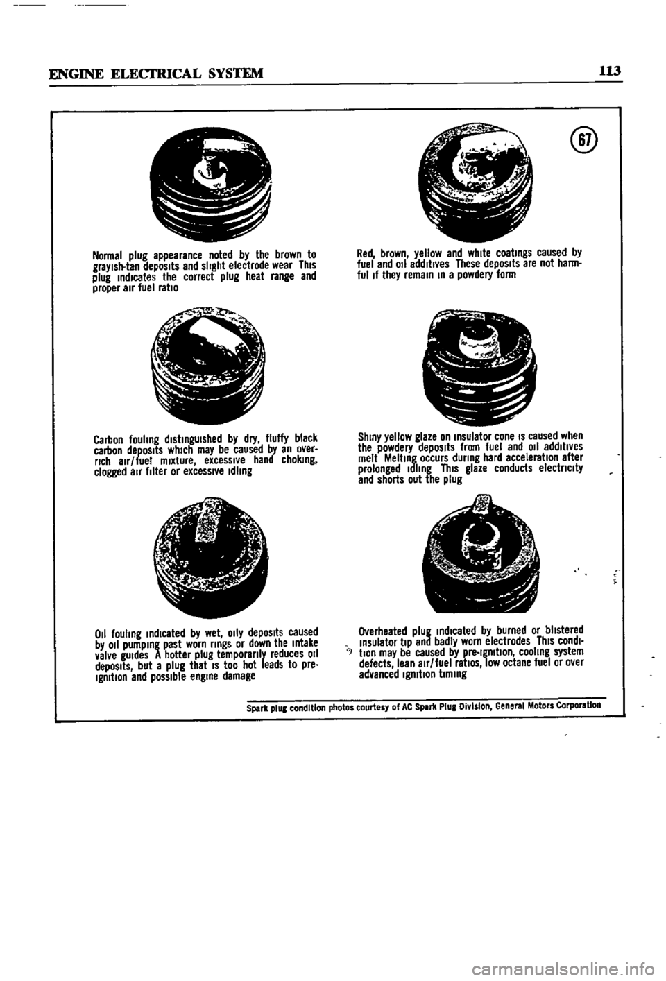
Normal
plug
appearance
noted
by
the
brown
to
graYlsll
lan
depOSits
and
slight
eleclrode
wear
This
plug
indicates
the
correct
plug
heal
range
and
proper
air
fuel
ratio
jI
Jo
t
Ql
i
Carbon
fouhng
distinguished
by
dry
fluffy
black
carbon
depOSits
which
may
be
caused
by
an
over
rich
alr
lue
mixture
excessive
hand
choking
clogged
air
filler
or
excessl
e
Idling
t
I
j
if
r
l
1
tfc
ji
0
1
fouling
indicated
by
wet
o
ly
depOSits
caused
by
011
pumping
past
worn
rings
or
down
the
Intake
valve
gUIdes
A
hotter
plug
temporanly
reduces
011
depOSits
but
a
plug
that
IS
too
hot
leads
to
pre
Ignition
end
possible
engine
damage
@
Red
brown
yellow
and
white
coatings
caused
by
luel
and
011
addltl
es
These
depOSits
are
not
harm
ful
If
they
remain
In
a
powdery
lorm
pr
11
L
J
J
S
C
ShinY
yellow
glaze
on
Insulalor
cone
IS
caused
when
the
powdery
depOSits
from
fuel
and
011
addltl
es
melt
Melting
occurs
during
hard
acceleration
alter
prolonged
Idling
This
glaze
conducts
electnclty
and
shorts
out
the
plug
e
1
A
I
A
I
7
Overheated
plug
indIcated
by
burned
or
blistered
Insulator
tiP
and
badly
worn
electrodes
ThiS
condl
J
tlon
may
be
caused
by
pre
Ignition
cooling
system
defects
lean
alr
luel
ratiOS
low
octane
luel
or
o
er
advanced
Ignition
timing
Spark
plUI
condition
photos
courtesy
of
AC
SPIr1l
Plug
Olv
s
on
Gene
MolDrs
Corporlllon
Page 124 of 252
EMISSION
CONTROL
S
IS
TEM
SEDAN
AND
SlATION
YfAGON
Yfl
tH
AUTOMATIC
TRANSMISSION
TO
DISTRIBUTOR
IGNITION
COIL
IGNITION
SWITCH
tnE
RETARDED
BREAKER
POINT
1
SPEED
SWITCH
THROTTLE
SWITCH
SWITCH
DETECTING
WIDE
OPEN
THROTTLE
POSITION
SWITCH
DETECTING
CLOSE
THROTTLE
POS
iION
Q
Z
S
e
l
Page 153 of 252

148
CHAPTER
ELEVEN
1
Insert
key
in
IgnItion
switch
and
turn
to
first
posltlon
2
Depress
accelerator
pedal
fully
LISten
for
the
solenOId
to
click
If
a
clIck
is
heard
the
solenoid
is
operating
correctly
3
Replace
solenoid
if
click
IS
not
heard
Before
replacing
solenoid
dram
apprOlumately
2
pInts
of
transmission
011
from
tranSmISsion
Re
fill
when
solenoid
replacement
is
complete
4
If
solenoId
IS
operatlng
correctly
but
trouble
persISts
check
WIres
for
continuity
With
electri
cal
tester
Linkage
Inspection
and
Adjustment
To
inspect
and
adjust
the
linkage
on
the
transmission
proceed
as
follows
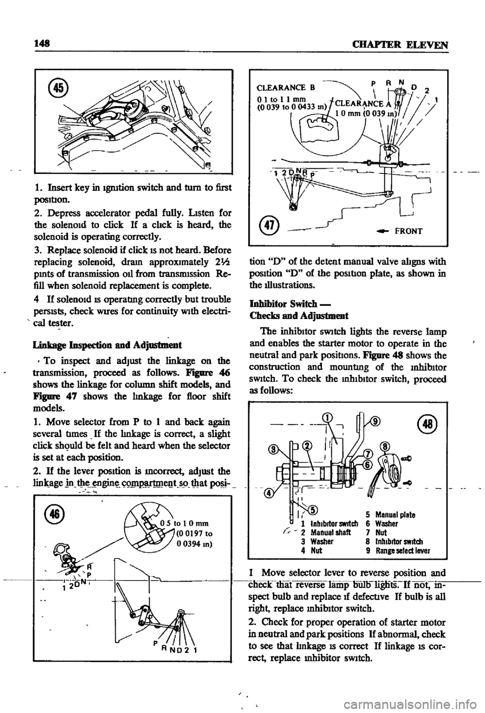
Figure
4
j
shows
the
linkage
for
column
shift
models
and
Figure
47
shows
the
lInkage
for
floor
shift
models
1
Move
selector
from
P
to
1
and
back
again
several
tImes
If
the
lInkage
is
correct
a
slight
click
sh
uld
be
felt
and
heard
when
the
selector
is
set
at
each
position
2
If
the
lever
position
is
mcorrect
adjust
the
lin
age
in
t
ie
ngin
C
Q1I1
lT
me
t
s9
mat
f46
OSIoI0mm
00197
to
mJ
r2
oN
k
@
FRONT
tion
D
of
the
detent
manual
valve
alignS
with
posItion
D
of
the
pOSItIon
plate
as
shown
in
the
illustrations
Inhibitor
Switc
h
Checks
and
Adjustment
The
inhibItor
SWitch
lights
the
reverse
lamp
and
enables
the
starter
motor
to
operate
in
the
neutral
and
park
positIons
Figure
48
shows
the
construction
and
mountlng
of
the
InhibItor
SWitch
To
check
the
mhIbltor
switch
proceed
as
follows
r
I
5
1
InhIbitor
switch
2
Menual
shalt
3
Washer
4
Nut
5
Manual
plate
6
Washer
7
Nut
8
Inhibitor
switch
9
Range
select
Iner
1
Move
selector
lever
to
reverse
position
and
clieck
that
reverse
lamp
bun
lignts
If
not
in
spect
bulb
and
replace
1f
defectlve
If
bulb
is
all
right
replace
mhibItor
switch
2
Check
for
proper
operation
of
starter
motor
in
neutral
and
park
positions
If
abnormal
check
to
see
that
lInkage
IS
correct
If
linkage
IS
cor
rect
replace
Inhibitor
SWitch
Page 211 of 252
206
CHAPTER
FIFrEEN
CD
ROOM
lAMP
2
VOLTAGE
REGULATOR
SIDE
MARKER
LAMP
HEAD
LAMP
ALTERNATOR
DISTRIBUTOR
STARTER
MOTOR
IGNITION
COIL
FUEL
TANK
UNIT
COMBINATION
LAMP
LICENCE
lAMP
1
Engme
room
harness
2
Instrument
harness
3
Body
harness
CD