1967 CHEVROLET CAMARO Wiring
[x] Cancel search: WiringPage 617 of 659

ACCESSORIES
15-8
BROWN
BRAKE
SWITCH
+12V *
BLACK
CONNECTOR
AT FUSE BLOCK
CRUISE POSITION
BUTTON RELEASED
ENGAGE POSITION
BUTTON PARTIALLY DEPRESSED^ N. ENOAOi SWITCH
TRIM POSITION N. N. I
BUHON FULLY DEPRESSED. \ ^
BROWN
BLUE
ENGAGE SWITCH
CONFIGURATION
BLACK
BLUE
REGULATOR
- SOLENOID COIL
(5 a RESISTANCE)
9 BLACK
BLUE
REGULATOR
Fig.
10 - Wiring Diagram
Replacement
1.
Insert the switch into the turn signal knob, push the
retaining ring firmly against the switch, and push the
operating button onto the switch plunger. " .
SERVO
Service
—
H the Servo unit is found to be defective, re-
placement is required. Note the condition of the hoses
and replace any which are cracked or deteriorated.
CHEVROLET CHASSIS SERVICE MANUAL
Page 618 of 659

ACCESSORIES 15-9
Adjustment- Adjust the bead chain so that it is as tight
as possible without holding the throttle open when the
carburetor is set at its lowest idle throttle position.
When connecting the bead chain (engine stopped) manually
set the fast idle cam at its lowest step and connect the
chain so that it does not hold the idle screw off the cam.
If the chain needs to be cut, cut it three beads beyond the
bead which pulls the linkage.
REGULATOR
Service - A defective regulator, that is one which is not
simply out of adjustment, must be replaced. During re-
placement, check the hoses which connect to the regulator
and replace any which are cracked or deteriorated.
Air Filter
The air filter located in the solenoid cover should be
cleaned and re-oiled at engine oil change intervals.
1.
Snap the solenoid cover off.
2.
Remove the filter and wash it in kerosene or mineral
spirits. Squeeze it dry and wet with SAE 10 engine
oil.
Squeeze out excess oil and reinstall into the
cover.
3.
Attach the cover with neoprene seal to the solenoid
housing. Be certain that the cover fits tightly to the
housing.
One regulator adjustment is possible: Engagement-
Cruising Speed Zeroing (to remove any difference be-
tween engagement and cruising speed).
NOTE:
No regulator adjustment should be
made, however, until the following items have
been checked or serviced:
1.
Bead chain properly adjusted.
2.
All hoses in good condition, properly attached, not
leaking, not pinched or kinked.
3.
Regulator air filter clean and properly oiled.
4.
Electric and vacuum release switches properly
adjusted.
Engagement—Cruising Speed Zeroing
If the cruising speed is lower than the engagement
speed, loosen the orifice tube locknut and turn the tube
outward; if higher, turn the tube inward. Each 1/8 turn
will alter the engagement-cruising speed difference one
mph. Tighten the locknut after adjustment and check the
system operation at 50 mph.
ELECTRICAL SYSTEM CHECK OUT
1.
Check fuse and connector.
2.
Check electric brake switch as follows: Unplug con-
nector at brake switch. Connect ohmmeter at points
A and B on brake switch. The ohmmeter must indi-
cate infinity when the brake pedal is depressed and
continuity when pedal is released. The cruise re-
lease brake switch (electric) is adjusted as is the
standard stop light brake switch. Replace electric
brake switch if needed.
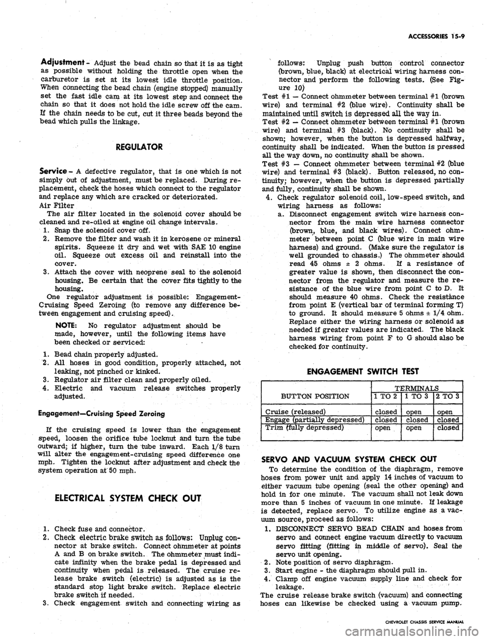
3.
Check engagement switch and connecting wiring as
follows: Unplug push button control connector
(brown, blue, black) at electrical wiring harness con-
nector and perform the following tests. (See Fig-
ure 10)
Test #1
—
Connect ohmmeter between terminal #1 (brown
wire) and terminal #2 (blue wire). Continuity shall be
maintained until switch is depressed all the way in.
Test #2
—
Connect ohmmeter between terminal #1 (brown
wire) and terminal #3 (black). No continuity shall be
shown; however, when the button is depressed halfway,
continuity shall be indicated. When the button is pressed
all the way down, no continuity shall be shown.
Test #3 — Connect ohmmeter between terminal #2 (blue
wire) and terminal #3 (black). Button released, no con-
tinuity; however, when the button is depressed partially
and fully, continuity shall be shown.
4.
Check regulator solenoid coil, low-speed switch, and
wiring harness as follows:
a. Disconnect engagement switch wire harness con-
nector from the main wire harness connector
(brown, blue, and black wires). Connect ohm-
meter
'
between point C (blue wire in main wire
harness) and ground. (Make sure the regulator is
well grounded to chassis.) The ohmmeter should
read 45 ohms ± 2 ohms. If a resistance of
greater value is shown, then disconnect the con-
nector from the regulator and measure the re-
sistance of the blue wire from point C to D. It
should measure 40 ohms. Check the resistance
from point E (vertical bar of terminal forming T)
to ground. It should measure 5 ohms ± 1/4 ohm.
Replace either the wiring harness or solenoid as
needed if greater values are indicated. The black
harness wiring from point F to G should also be
checked for continuity.
ENGAGEMENT SWITCH TEST
BUTTON POSITION
Cruise (released)
Engage (partially depressed)
Trim (fully depressed)
TERMINALS
1 TO 2
closed
Closed
open
1 TO 3
open
closed
open
2 TO 3
open
closed
closed
SERVO AND VACUUM SYSTEM CHECK OUT
To determine the condition of the diaphragm, remove
hoses from power unit and apply 14 inches of vacuum to
either vacuum tube opening (seal the other opening) and
hold in for one minute. The vacuum shall not leak down
more than 5 inches of vacuum in one minute. If leakage
is detected, replace servo. To utilize engine as a vac-
uum source, proceed as follows:
1.
DISCONNECT SERVO $EAD CHAIN and hoses from
servo and connect engine vacuum directly to vacuum
servo fitting (fitting in middle of servo). Seal the
servo unit opening.
2.
Note position of servo diaphragm.
3.
Start engine - the diaphragm should pull in.
4.
Clamp off engine vacuum supply line and check for
leakage. '
The cruise release brake switch (vacuum) and connecting
hoses can likewise be checked using a vacuum pump.
CHEVROLET CHASSIS SERVICE MANUAL
Page 619 of 659

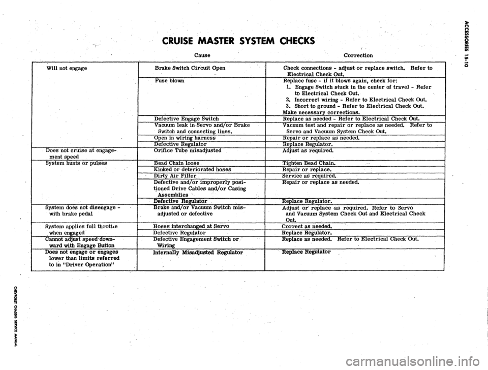
CRUISE MASTER SYSTEM CHECKS
Will not engage
Does not cruise at engage-
ment speed
System hunts or pulses
System does not disengage -
with brake pedal
System applies full throtUe
when engaged
Cannot adjust speed down-
ward with Engage Button
Does not engage or engages
lower than limits referred
to in "Driver Operation"
Cause
Brake Switch Circuit Open
Fuse blown
Defective Engage Switch
Vacuum leak in Servo and/or Brake
Switch and connecting lines.
Open in wiring harness
Defective Regulator
Orifice Tube misadjusted
Bead Chain loose.
Kinked or deteriorated hoses
Dirty Air Filter
Defective and/or improperly posi-
tioned Drive Cables and/or Casing
Assemblies
Defective Regulator
Brake and/or Vacuum Switch mis-
adjusted or defective
Hoses interchanged at Servo
Defective Regulator
Defective Engagement Switch or
Wiring
Internally Misadjusted Regulator
Correction
Check connections - adjust or replace switch. Refer to
Electrical Check Out.
Replace fuse - if it blows again, check for:
1.
Engage Switch stuck in the center of travel - Refer
to Electrical Check Out.
2.
Incorrect wiring - Refer to Electrical Check Out.
3.
Short to ground - Refer to Electrical Check Out.
Make necessary corrections.
Replace as needed - Refer to Electrical Check Out.
Vacuum test and repair or replace as needed. Refer to
Servo and Vacuum System Check Out.
Repair or replace as needed.
Replace Regulator.
Adjust as required.
Tighten Bead Chain.
Repair or replace.
Service as required.
Repair or replace as needed.
Replace Regulator.
Adjust or replace as required. Refer to Servo
and Vacuum System Check Out and Electrical Check
Out.
Correct as needed.
Replace Regulator.
Replace as needed. Refer to Electrical Check Out.
Replace Regulator
Page 643 of 659

SPECIFICATIONS
16
COIL
Ignition Coil
Application
Primary Resistance-Ohms
Secondary Resistance-Ohms
Ignition Resistor:
Type
Ohms
L-4 & L-6
1.45-1.63
5600-6900
1.8
V-8 (Non-Transistor)
1.24-1.46
6500-9500
Fixed (In Wiring Harness)
1.8
V-8 (Transistor)
.38-.51
8200-12,400
.43 & .68
CHEVROLET CHASSIS SERVICE MANUAL
Page 652 of 659

SPECIFICATIONS 25
BODY AND CHASSIS ELECTRICAL
SECTION
12
LAMP USAGE
CANDLE
POWER
BULB
NUMBER
Headlamp Unit
Chevrolet, Chevelle & Corvette
Outer - High Beam
Outer - Low Beam
Inner -• High Beam only
Chevy H
High Beam . .
Low Beam
Parking Lamp and Directional Signal
All Exc. Camaro
Camaro
Tail, Stop and Directional Signal (Exc. Bel Air)
Backing Lamp ••...,
Instrument Illumination Lamps
Chevrolet & Camaro ,
Chevelle and Chevy n
Corvette
Temperature Indicator
Chevrolet & Camaro
Chevelle and Chevy II .............
Oil Pressure Indicator
Chevrolet & Camaro .............
Chevelle and Chevy II
Generator Indicator
Chevrolet & Camaro .
Chevelle and Chevy n ,
Hi-Beam Indicator
Chevrolet & Camaro <
Chevelle and Chevy II
Corvette , . • . ,
Directional Indicator
Chevrolet & Camaro
Chevelle & Chevy II . .
Corvette . .
Cigarette Lighter Lamp
Corvette .
Ignition Lock Lamp
Chevrolet . . .
Corvette . . .
Heater or A/C Control Panel
Chevrolet, Chevelle, Chevy n & Camaro . . .
Corvette . . .
Glove Box Lamps
Chevrolet, Chevelle, Chevy n & Camaro . . .
Corvette . . . . .
Dome and Courtesy Lamps
Cartridge Type (AU)
Bayonet Type (Exc. Corvette) . . .
Corvette ,
Convertible . .
37 1/2 Watts
55 Watts
37 1/2 Watts
55 Watts
45 Watts
4-32
4-32
4-32
Special Fiber
1
2
3
2
3
12
6
6
6
Optic
4002
4002
4001
6012
1157
1034-A
1157
1156
194
1895
.
1816
194
1895
194
1895
194
1895
194
1895
1445
194
1895
1816
1445
Wiring
1445
1895
1893
1895
1893
211
89,
212
90
631
CHEVROLET CHASSIS SERVICE MANUAL