1967 CHEVROLET CAMARO wheel
[x] Cancel search: wheelPage 245 of 659

BRAKES 5-12
VIEW B
Fig.
21—Parking Brake System-Chevy II
2.
Remove return spring at equalizer.
3.
Remove equalizer check nut, and separate cable
stud from equalizer.
4.
Remove clamp from underbody guide bracket. (Con-
vertible models only, also remove clamp from guide
bracket at underbody support.)
5. Remove cable retainer from underbody bracket.
6. Compress expanded conduit locking fingers at toe
pan,
remove cable ball from idler lever, and with-
draw cable from car.
Installation
1.
Position cable ball and conduit tip through cutout
in toe pan.. Make sure conduit locking fingers are
fully expanded and secured in cutout, then position
cable ball in idler lever clevis.
2.
Present parking brake lever to one notch.
3.
P}ace retainer in conduit groove so that conduit
end is secure in underbody bracket.
4.
Position cable in guide bracket(s) and secure cable
in bracket with clamp(s).
5. Place one check nut on cable stud and insert stud
into equalizer, then place second check nut on stud.
6. Connect cable return spring.
7. Adjust parking brake as outlined in this section.
8. Connect positive battery cable.
Rear Cable
Removal
1.
Place parking brake lever in released position.
2.
Disconnect front cable return spring at equalizer.
3.
Remove check nut from front cable stud, withdraw
stud from equalizer, and remove equalizer from
rear cable.
4.
Remove retainers from grooves in rear cable con-
duit, and remove cable from bracket.
5. Remove cable from center body bumper bracket
and spring clip at shock absorber lower mount.
6. Back off rear service brakes sufficiently to allow
for drum removal.
7. Remove both rear wheels and drums.
8. Remove secondary brake shoe return spring.
9. Remove secondary brake shoe hold-down spring
and pin.
10.
Remove cable end from parking brake actuating
lever.
11.
Compress expanded conduit locking fingers at flange
plate entry hole and withdraw cable.
CHEVROLET CHASSIS SERVICE MANUAL
Page 246 of 659

Installation
1.
Pass end of cable and conduit tip through flange
plate entry hole, making sure that conduit locking
fingers all expand fully.
2.
Compress retaining spring and place cable end in
actuating lever.
3.
Install secondary shoe hold-down pin and spring.
4.
Install secondary shoe return spring.
5. Install drum and wheel.
6. Snap cable conduit into spring clip at shock ab-
sorber lower mount.
7. Install cable conduit in bracket at center body bump-
er bracket.
8. Position cable conduit ends in cable bracket and
install retainers in grooves.
9. Place equalizer on cable and insert forward cable
stud. Install check nut and return spring.
NOTE:
To perform its intended function, equal-
izer must be free to slide on rear cable. Lubri-
cate cable at equalizer with chassis grease.
10.
Adjust rear service brakes and parking brake as
outlined in this section.
BRAKES 5-13
PARKING BRAKE-CORVETTE (Fig. 22)
Lever Assembly
Removal
1.
Place parking brake lever in the fully released
position.
2.
Under vehicle, unhook and remove return, spring.
3.
Remove rear nut from cable stud at equalizer and
allow front cable to hang down.
4.
Inside vehicle, remove six screws securing cover
to underbody. It is necessary to push the seat
cushion down as shown in Figure 23 to gain access
to the lower mounting screw on each side. Remove
the retainer. Lift the cover upward and to the
rear to allow seal to slide out of cover slot and
remove cover.
5. Remove trim seal from lever (fig. 24).
6. Remove screw and washer securing parking brake
alarm switch to side of lever assembly.
7. Remove four bolts securing lever assembly to under-
body and lift lever assembly upward. Remove lever
forward mounting bracket.
Fig.
22—Parking Brake System—Corvette
CHEVROLET CHASSIS SERVICE MANUAL
Page 247 of 659

BRAKES 5-14
Fig.
23—Removing or Installing Cover Lower Mounting Screws
Fig.
24—Removing or Installing Trim Seal
8. Remove front cable from lever assembly using long
nose pliers as shown in Figure 25. Remove lever
from vehicle.
Installation
1.^
Install front cable in lever assembly using long
nose pliers as shown in Figure 25. Slide slack
cable through hole and place lever assembly in
position.
2.
Place forward mounting bracket in position and
secure plate and lever assembly to underbody with
four mounting bolts.
3.
Secure parking brake alarm switch to side of lever
assembly with washer and screw (fig. 24).
4.
Install trim seal on lever (fig. 24).
5. Insert the end of the trim seal into the slot in the
cover and slide the cover forward and down into
position.
6. Place the retainer in position. Secure retainer and
cover to underbody with six screws. It is necessary
to push the seat cushion down as shown in Figure 23
to gain access to the lower mounting screw hole on
each side.
7. Under vehicle, insert front cable stud through equal-
izer assembly and secure with nut.
8. Install return spring.
9. Adjust parking brake as outlined under Maintenance
and Adjustments in this section.
Front Cable
Removal
1.
Perform the complete parking brake lever removal
procedure above.
2.
Under vehicle, remove nut, washer, and bolt se-
. curing pulley to pulley bracket (fig. 22).
3.
Remove seal grommet from underbody cable hole.
4.
Pull front cable out of vehicle.
Installation
1.
Install seal grommet around front cable.
2.
Slide front cable into position through cable hole
and work seal grommet into installed position.
3.
Under vehicle, loop front cable around pulley wheel
and secure pulley wheel to bracket with bolt, washer,
and nut (fig..22).
4.
Perform the complete parking brake lever installa-
tion procedure above.
Removal
1.
Remove the cable clip retainers on the back side of
the frame rail from each of the rear brake cable
ends.
2.
Disconnect the cable at the rear wheel flange plate.
3.
Remove the cable ball out of the recess in .the brake
lever assembly clevis.
4.
Disconnect the cables at the equalizer connector and
remove the cables.
Installation
1.
Attach the rear cable balls on the rear cable ends
to the rear wheel recess in the brake lever assembly
clevis.
2.
Attach the cable assembly to the rear wheel flange
plate.
3.
Connect the cable assemblies along the frame rail
area.
4.
Insert the cable end through the equalizer and attach
to the equalizer connector.
5. Adjust as outlined under Maintenance and
Adjustments.
6. Lubricate the cables and all moving parts for
trouble-free operation—see Lubrication, Section 0.
Fig.
25—Removing or Installing Front Cable
CHEVROLET CHASSIS SERVICE MANUAL
Page 249 of 659
BRAKES 5-16
6Y. Adjust clutch pedal travel as outlined in
Section 7.
SHOES AND LININGS
Organic Linings
NOTE:
If brake drums are worn severely, it
may be necessary to retract the adjusting screw.
To gain access to the adjusting screw star
wheel, knock out the lanced area in the web of
the brake drum using a chisel or similar tool.
Release the actuator from the star wheel by
lifting with a small screw driver and back off
the star wheel with a second screw driver (press
down on the handle to retract shoes).
CAUTION: After knocking out the metal, be
sure to remove it from the inside of the drum .
and clean all metal from the brake compartment.
A new hole cover must be installed when drum
is reinstalled.
Removal
1.
Raise the vehicle and plate on jack stands.
2.
Loosen check nuts at parking brake equalizer suffi-
ciently to remove, all tension from brake cable.
3.
Remove brake drums.
NOTE:
Since there are wheel cylinder piston
stops to prevent pistons from leaving cylinders,
it is not necessary to install wheel cylinder
clamps when brake shoes are removed; however,
brake pedal must not be depressed while drums
are removed.
4.
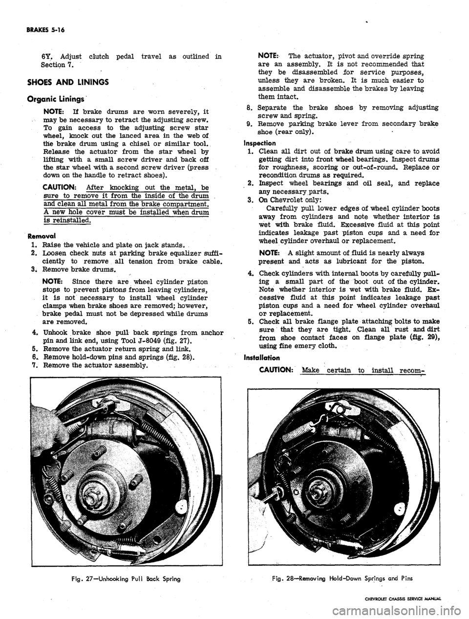
Unhook brake shoe pull back springs from anchor
pin and link end, using Tool J-8049 (fig. 27).
5. Remove the actuator return spring and link.
6. Remove hold-down pins and springs (fig. 28).
7. Remove the actuator assembly.
NOTE:
The actuator, pivot and override spring
are an assembly. It is not recommended that
they be disassembled for service purposes,
unless they are broken. It is much easier to
assemble and disassemble the brakes by leaving
them intact.
8. Separate the brake shoes by removing adjusting
screw and spring.
9. Remove parking brake lever from secondary brake
shoe (rear only).
Inspection
1.
Clean all dirt out of brake drum using care to avoid
getting dirt into front wheel bearings. Inspect drums
for roughness, scoring or out-of-round. Replace or
recondition drums as required.
2.
Inspect wheel bearings and oil seal, and replace
any necessary parts.
3.
On Chevrolet only:
Carefully pull lower edges of wheel cylinder boots
away from cylinders and note whether interior is
wet with brake fluid. Excessive fluid at this point
indicates leakage past piston cups and a need for
wheel cylinder overhaul or replacement.
NOTE:
A slight amount of fluid is nearly always
present and acts as lubricant for the piston.
4.
Check cylinders with internal boots by carefully pull-
ing a small part of the boot out of the cylinder.
Note whether interior is wet with brake fluid. Ex-
cessive fluid at this point indicates leakage past
piston cups and a need for wheel cylinder overhaul
or replacement.
5. Check all brake flange plate attaching bolts to make
sure that they are tight. Clean all rust and dirt
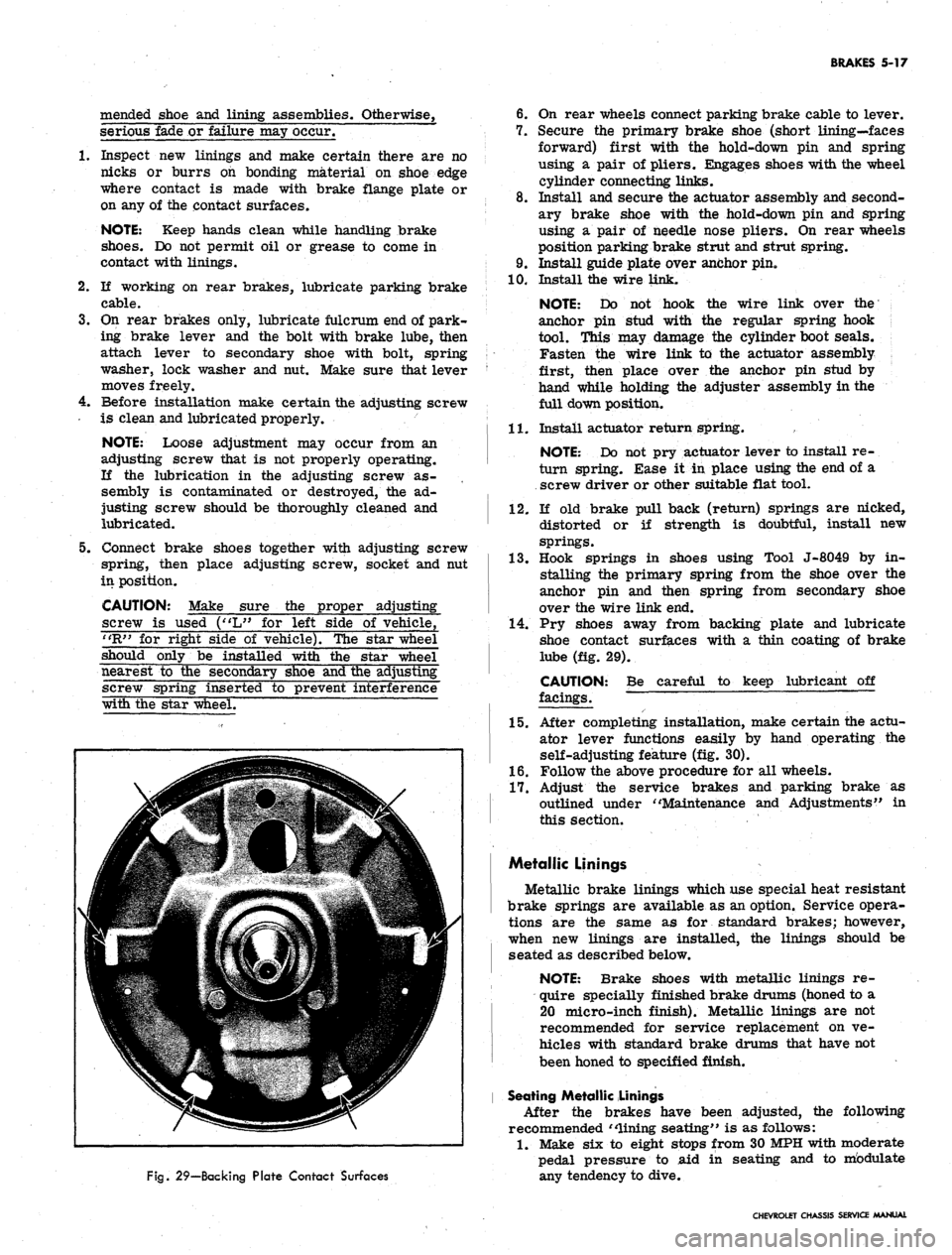
from shoe contact faces on flange plate (fig. 29),
using fine emery cloth.
Installation
CAUTION: Make certain to install recom-
Fig.
27-Unhooking Pull Back Spring
Fig.
28—Removing Hold-Down Springs and Pins
CHEVROLET CHASSIS SERVICE MANUAL
Page 250 of 659
BRAKES 5-17
mended shoe and lining assemblies. Otherwise,
serious fade or failure may occur.
1.
Inspect new linings and make certain there are no
nicks or burrs on bonding material on shoe edge
where contact is made with brake flange plate or
on any of the contact surfaces.
NOTE: Keep hands clean while handling brake
shoes.
Do not permit oil or grease to come in
contact with linings.
2.
If working on rear brakes, lubricate parking brake
cable.
3.
On rear brakes only, lubricate fulcrum end of park-
ing brake lever and the bolt with brake lube, then
attach lever to secondary shoe with bolt, spring
washer, lock washer and nut. Make sure that lever
moves freely.
4.
Before installation make certain the adjusting screw
is clean and lubricated properly.
NOTE: Loose adjustment may occur from an
adjusting screw that is not properly operating.
If the lubrication in the adjusting screw as-
sembly is contaminated or destroyed, the ad-
justing screw should be thoroughly cleaned and
lubricated.
5.
Connect brake shoes together with adjusting screw
spring, then place adjusting screw, socket and nut
in position.
CAUTION: Make sure the proper adjusting
screw is used ("L" for left side of vehicle,
"R"
for right side of vehicle). The star wheel
should only be installed with the star wheel
nearest to the secondary shoe and the adjusting
screw spring inserted to prevent interference
with the star wheel.
6. On rear wheels connect parking brake cable to lever.
7.
Secure the primary brake shoe (short lining—faces
forward) first with the hold-down pin and spring
using a pair of pliers. Engages shoes with the wheel
cylinder connecting links.
8. Install and secure the actuator assembly and second-
ary brake shoe with the hold-down pin and spring
using a pair of needle nose pliers. On rear wheels
position parking brake strut and strut spring.
9. Install guide plate over anchor pin.
10.
Install the wire link.
NOTE: Do not hook the wire link over the
anchor pin stud with the regular spring hook
tool. This may damage the cylinder boot seals.
Fasten the wire link to the actuator assembly ;
first, then place over the anchor pin stud by
hand while holding the adjuster assembly in the
full down position.
11.
Install actuator return spring.
NOTE: Do not pry actuator lever to install re-
turn spring. Ease it in place using the end of a
screw driver or other suitable flat tool.
12.
If old brake pull back (return) springs are nicked,
distorted or if strength is doubtful, install new
springs.
13.
Hook springs in shoes using Tool J-8049 by in-
stalling the primary spring from the shoe over the
anchor pin and then spring from secondary shoe
over the wire link end.
14.
Pry shoes away from backing plate and lubricate
shoe contact surfaces with a thin coating of brake
lube (fig. 29).
CAUTION:
facings.
Be careful to keep lubricant off
Fig.
29—Backing Plate Contact Surfaces
15.
After completing installation, make certain the actu-
ator lever functions easily by hand operating the
self-adjusting feature (fig. 30).
1.6. Follow the above procedure for all wheels.
17.
Adjust the service brakes and parking brake as
outlined under "Maintenance and Adjustments" in
this section.
Metallic Linings
Metallic brake linings which use special heat resistant
brake springs are available as an option. Service opera-
tions are the same as for standard brakes; however,
when new linings are installed, the linings should be
seated as described below.
NOTE: Brake shoes with metallic linings re-
quire specially finished brake drums (honed to a
20 micro-inch finish). Metallic linings are not
recommended for service replacement on ve-
hicles with standard brake drums that have not
been honed to specified finish.
Seating Metallic Linings
After the brakes have been adjusted, the following
recommended "lining seating" is as follows:
1.
Make six to eight stops from 30 MPH with moderate
pedal pressure to aid in seating and to mbdulate
any tendency to dive.
CHEVROLET CHASSIS SERVICE MANUAL
Page 252 of 659
BRAKES 5-19
correct service parts when servicing a Bendix main
cylinder.
1.
The two-letter identification stamp on the end of
the master cylinder indicates the displacement capa-
bilities of that particular cylinder. Master cylinders
should only be replaced with another cylinder bearing
the same two-letter identification.
2.
The length of the component pistons in the master
cylinders are critical factors in displacement capa-
bilities of a particular master cylinder. These
pistons are coded, using rings or grooves in the
shank of the piston. It is mandatory that when
pistons are replaced, the replacing piston must con-
tain the same identification marks and the same
contour at the push rod end as the piston which
is removed.
Delco Moraine dual master cylinders, used with
drum-type brakes, contain a rubber check valve and
check valve spring in each outlet boss. When the
car is equipped with disc brakes on the front and
drum brakes on the rear, the dual master cylinder
will have a check valve and spring in the outlet
boss for the rear brakes. No check valve is required
for four wheel disc brakes, and, therefore, the outlet
1.
Spring
2.
Check Valve
3. Valve Seat
4.
Bleeder Valve
5. Bail Wire
6. Cover
7. Diaphragm
8. Stop Screw
9. Body
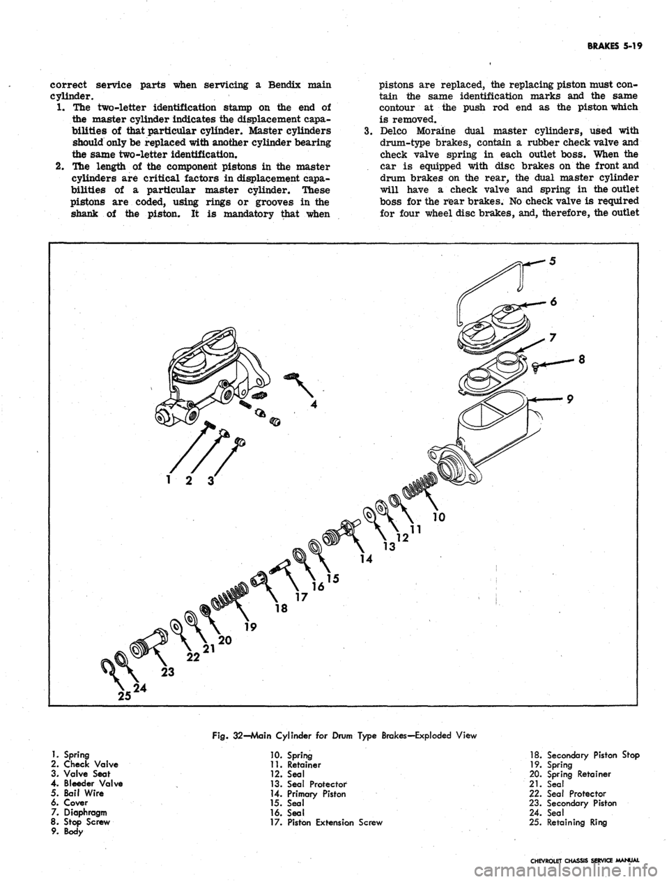
Fig.
32-Main Cylinder for Drum Type Brakes-Exploded View
10.
Spring
11.
Retainer
12.
Seal
13.
Seal Protector
14.
Primary Piston
15.
Seal
16.
Seal
17.
Piston Extension Screw
18.
Secondary Piston Stop
19.
Spring
20.
Spring Retainer
21.
Seal
22.
Seal Protector
23.
Secondary Piston
24.
Seal
25.
Retaining Ring
CHEVROLET CHASSIS SERVICE MANUAL
Page 254 of 659
BRAKES 5-21
brake fluid. Coat the primary and secondary seals
on the secondary piston with clean brake fluid. Insert
the secondary piston spring retainer into the sec-
ondary piston spring. Place the retainer and spring
down over the end of the secondary piston until the
retainer locates inside of the lips of the primary
cup.
10.
Hold the master cylinder with the open end of the
bore down. Push the secondary piston into the bore
until the spring seats against the closed end of the
bore.
11.
Position the master cylinder in a vise with the
open end of the bore up. Coat the primary and
secondary seal on the primary piston with clean
brake fluid. Push the primary piston assembly,
spring end first, into the bore of the master cylinder*
Hold the piston down and snap the lock ring into
position in the small groove in the I.D. of the bore.
12.
Push the primary piston down to move the secondary
piston forward far enough to clear the stop screw
hole in the bottom of the front fluid reservoir. Install
the stop screw.
13.
Install reservoir diaphragm in the reservoir cover
and install the cover on the main cylinder. Push
bail wire into position to secure the reservoir cover.
Installation
1.
Assemble the push rod through the push rod retainer,
if it has been disassembled.
2.
Push the retainer over the end of the main cylinder.
Assemble new boot over push rod and press it down
over the push rod retainer. Slide new mounting
gasket into position.
3.
Secure .the main cylinder to the firewall with mount-
ing bolts.
4.
Connect the push rod clevis to the brake pedal with
pin and retainer.
5. Connect the brake lines to the main cylinder.
6. Fill the main cylinder reservoirs to the levels
shown in Figure 8. Bleed the brake system as out-
lined in this section.
7. K necessary, adjust the brake pedal free play as
outlined in this section.
WHEEL CYLINDER (Fig. 33)
The wheel cylinder boots should be removed from a
cylinder body only when they are visibly damaged or
leaking fluid. Wheel cylinders having torn, cut, or heat-
cracked boots should be completely overhauled.
Removal
1.
Raise vehicle and place on jack stands.
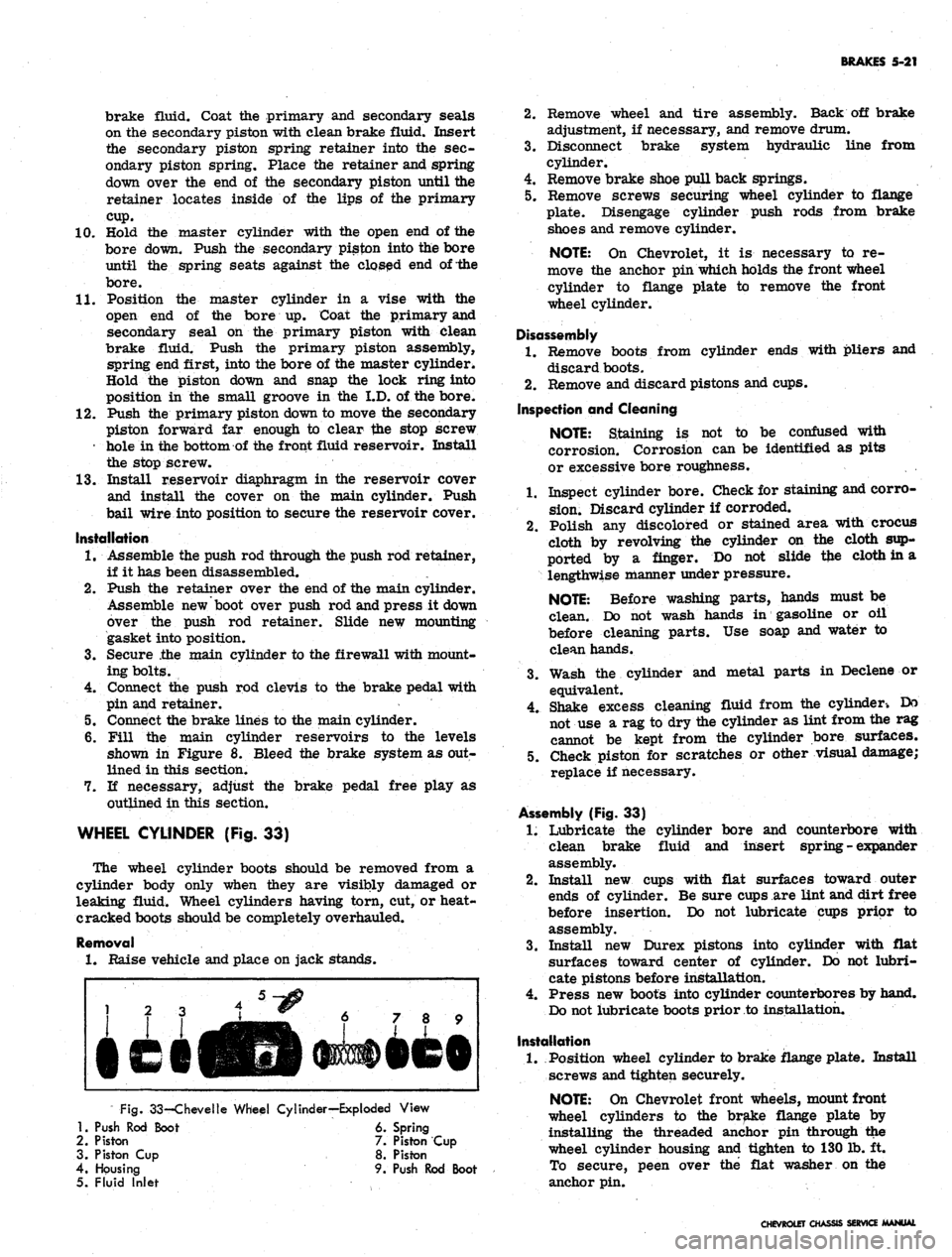
Fig.
33-Chevelle Wheel Cylinder—Exploded View
1.
Push Rod Boot 6. Spring
2.
Piston 7. Piston Cup
3. Piston Cup 8. Piston
4.
Housing 9. Push Rod Boot
5. Fluid Inlet
2.
Remove wheel and tire assembly. Back off brake
adjustment, if necessary, and remove drum.
3.
Disconnect brake system hydraulic line from
cylinder.
4.
Remove brake shoe pull back springs.
5. Remove screws securing wheel cylinder to flange
plate. Disengage cylinder push rods from brake
shoes and remove cylinder.
NOTE:
On Chevrolet, it is necessary to re-
move the anchor pin which holds the front wheel
cylinder to flange plate to remove the front
wheel cylinder.
Disassembly
1.
Remove boots from cylinder ends with pliers and
discard boots.
2.
Remove and discard pistons and cups.
Inspection and Cleaning
NOTE:
Staining is not to be confused with
corrosion. Corrosion can be identified as pits
or excessive bore roughness.
1.
Inspect cylinder bore. Check for staining and corro-
sion.
Discard cylinder if corroded.
2.
Polish any discolored or stained area with crocus
cloth by revolving the cylinder on the cloth sup-
ported by a finger. Do not slide tfce cloth in a
lengthwise manner under pressure.
NOTE:
Before washing parts, hands must be
clean. Do not wash hands in gasoline or oil
before cleaning parts. Use soap and water to
clean hands.
3.
Wash the cylinder and metal parts in Declene or
equivalent.
4.
Shake excess cleaning fluid from the cylinder-. Do
not use a rag to dry the cylinder as lint from the rag
cannot be kept from the cylinder bore surfaces.
5. Check piston for scratches or other visual damage;
replace if necessary.
Assembly (Fig. 33)
1.
Lubricate the cylinder bore and counterbore with
clean brake fluid and insert spring - expander
assembly.
2.
Install new cups with flat surfaces toward outer
ends of cylinder. Be sure cups are lint and dirt free
before insertion. Do not lubricate cups prior to
assembly.
3.
Install new Durex pistons into cylinder with flat
surfaces toward center of cylinder. Do not lubri-
cate pistons before installation.
4.
Press new boots into cylinder counterbores by hand.
Do not lubricate boots prior to installation.
Installation
1.
Position wheel cylinder to brake flange plate. Install
screws and tighten securely.
NOTE:
On Chevrolet front wheels, mount front
wheel cylinders to the brake flange plate by
installing the threaded anchor pin through the
wheel cylinder housing and tighten to 130 lb. ft.
To secure, peen over the flat washer on the
anchor pin.
CHEVROLET CHASSIS SERVICE MANUAL
Page 255 of 659
BRAKES 5-22
2.
Replace ail push rods and pull back springs.
3.
Connect hose or line to wheel cylinder.
NOTE:
If replacing front wheel cylinder, con-
nect hose and inspect installation as outlined in
"Hydraulic Brake Hose Replacement".
4.
Install drum and wheel.
5. Bleed brakes as outlined in this section.
ANCHOR PIN
Front Wheel
1.
Raise front of vehicle and place on jack stands.
2.
Remove wheel and drum as outlined in this section.
3.
Remove brake shoe pull back springs, link and guide
plate.
4.
Disengage anchor pin lock and remove anchor pin by
turning counterclockwise.
5. Place new lock plate on anchor pin and pass pin
through the hole in flange plate and screw into tapped
hole in spindle support.
6. Torque pin to 130 lb. ft. and lock by peening over
washer tabs.
7. Install brake shoe guide plate, link and pull back
springs.
8. Adjust brakes, install drum and wheel as outlined
in this section. Test brake operation.
Rear Wheel
Two type anchor pins are used in production for the
rear wheels. The riveted type is not serviced and if
failure or damage should occur to either the anchor
pin or flange plate, both parts will have to be replaced
and the threaded type anchor pin used.
Threaded Type
1.
Raise rear of vehicle and place on jack stands,
2.
Remove wheel and drum as outlined in this section.
3.
Remove brake shoe pull back springs, link and guide
plate.
4.
Remove anchor pin retaining nut and washer and
remove pin from flange plate.
5. Position anchor pin to flange plate, install lock
washer and nut, and torque pin to 80 lb. ft.
6. Install brake shoe guide plate, link and pull back
springs.
7. Adjust brakes and install drum and wheel as outlined
in this section.
8. Test brake operation.
BRAKE DRUMS
Front brake drums are the demountable type; that is,
they can be removed without removing the hub. Rear
brake drums are demountable and may be removed
wihtout removing the axle shaft.
A lanced "knock out" area (fig. 34) is provided in
the web of the brake drum for servicing purposes in
the event retracting of the brake shoes is required in
order to remove the drum.
A small screw driver or hooked wire may be inserted
to disengage the automatic adjuster actuating lever so
the star wheel may be turned.
Removal
1.
Raise vehicle and place on jack stand.
2.
Remove wheel and tire assembly, back off brake
adjustment and remove drum.
Inspection and Reconditioning
Whenever brake drums are removed they should be
thoroughly cleaned and inspected for cracks, scores,
deep grooves, and out-of-round. Any of these conditions
must be corrected since they can impair the efficiency
of brake operation and also can cause premature failure
of other parts.
Smooth up any slight scores by polishing with fine
emery cloth. Heavy or extensive scoring will cause
excessive brake lining wear and it will probably be
necessary to rebore in order to true up the braking
surface.
An out-of-round drum makes accurate brake shoe
adjustment impossible and is likely to cause excessive
wear of other parts of brake mechanism due to its
eccentric action.
A drum that is more than .008" out-of-round on the
diameter is unfit for service and should be rebored.
Out-of^round, as well as taper and wear can be ac-
curately measured with an inside micrometer fitted
with proper extension rods.
If drum is to be rebored for use with standard size
brake facings which are worn very little, only enough
metal should be removed to obtain a true smooth braking
surface.
If drum has to be rebored more than .020" over the
standard diameter, it should be rebored to .060" diameter
oversize and the brake facing should be replaced with
.030"
oversize facings.
A brake drum must not be rebored more than .060"
over the maximum standard diameter, since removal
of more metal will effect, dissipation of heat and may
cause distortion of drum. Chevrolet brake facing is
not furnished larger than .030" oversize and this will
not work efficiently in drums bored more than .060"
oversize.
Brake drums may be refinished either by turning or
grinding. Best brake performance is obtained by turning
drums with a very fine feed. To insure maximum lining
life,
the refinished braking surface must be smooth and
free from chatter or tool marks, and run-out must not
exceed .005" total indicator reading.
Cleaning
New brake drums in parts stock are given a light.
coating of rust proofing oil to prevent the formation of
rust on the critical braking surfaces during the time
that the drums are in storage.
This rust proofing oil must be carefully removed
before the drum is placed in service to prevent any
of this oil from getting on the brake shoe facings, which
might cause an extreme brake grab condition.
It is recommended that a suitable volatile, non-toxic,
greaseless type solvent be used to clean the oil from the
braking surface of the new brake drums before they are
•placed in service to insure the cleanest possible surface.
Gasoline or kerosene should not be used as there is
danger that a portion of the diluated oil substance may
be left on the braking surface that may later cause
difficulty.
Installation
1.
Make brake adjustment as outlined in this section.
CHEVROLET CHASSIS SERVICE MANUAL