1953 JEEP DJ tires
[x] Cancel search: tiresPage 7 of 376
'Jeep*
UNIVERSAL SERIES
SERVICE
MANUAL
B
LUBRICATION
AND
PERIODIC SERVICES
Contents
PAR. SUBJECT
PAR.
SUBJECT
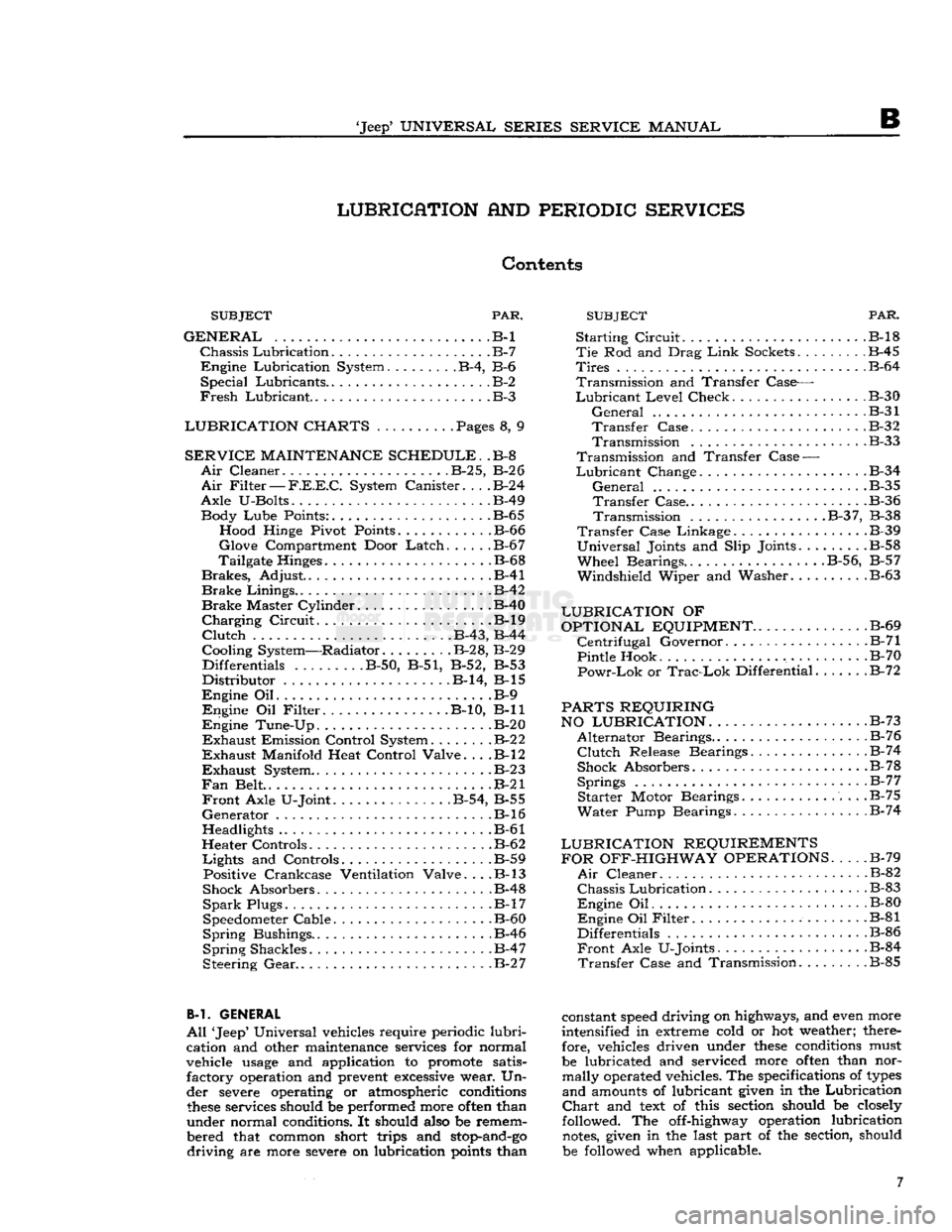
GENERAL
.B-l
Chassis
Lubrication
B-7
Engine
Lubrication System B-4, B-6
Special
Lubricants B-2
Fresh
Lubricant.
.B-3
LUBRICATION CHARTS
. Pages 8, 9
SERVICE
MAINTENANCE SCHEDULE.
.B-8
Air
Cleaner
B-2
5,
B-2
6
Air
Filter
—
F.E.E.C.
System Canister
B-2
4
Axle
U-Bolts B-49 Body
Lube
Points: B-65 Hood Hinge Pivot Points B-66
Glove
Compartment Door
Latch
B-6
7
Tailgate Hinges .B-68
Brakes,
Adjust .B-41
Brake
Linings .B-42
Brake
Master Cylinder B-40
Charging
Circuit
B-l9
Clutch
. B-43, B-44
Cooling System—Radiator. B-28, B-29 Differentials
........
.B-50, B-51, B-52, B-53
Distributor
B-14, B-l5
Engine
Oil B-9
Engine
Oil
Filter
B-10, B-ll
Engine
Tune-Up B-20
Exhaust
Emission Control System
B-2
2
Exhaust
Manifold Heat Control Valve. . . .B-l2
Exhaust
System
B-2 3
Fan
Belt . .B-21
Front
Axle U-Joint B-54, B-55
Generator
.B-16
Headlights B-61
Heater Controls B-62
Lights
and Controls B-59 Positive Crankcase Ventilation Valve. . . .B-l3
Shock Absorbers B-48
Spark
Plugs. B-17
Speedometer Cable. .B-60
Spring
Bushings.. . .B-46
Spring
Shackles .B-47
Steering
Gear
B-2 7
B-l. GENERAL
All
'Jeep' Universal vehicles require periodic
lubri
cation and other maintenance services for normal
vehicle
usage
and application to promote satis factory operation and prevent
excessive
wear. Un
der severe operating or atmospheric conditions
these
services should be performed more
often
than
under normal conditions. It should also be remem
bered that common short trips and
stop-and-go
driving
are more severe on lubrication
points
than
Starting
Circuit
B-l8
Tie
Rod and Drag
Link
Sockets
.
B-45
Tires
B-64
Transmission
and Transfer Case—
Lubricant
Level
Check B-30
General
B-31
Transfer
Case B-32
Transmission
.B-33
Transmission
and Transfer
Case
—
Lubricant
Change .B-34
General
.B-35
Transfer
Case B-36
Transmission
B-3
7, B-38
Transfer
Case Linkage B-39
Universal
Joints and Slip Joints.
.......
.B-58
Wheel
Bearings..
.........
. . .B-56, B-57
Windshield
Wiper and Washer B-63
LUBRICATION
OF
OPTIONAL EQUIPMENT
B-69
Centrifugal
Governor. .B-71
Pintle Hook .B-70
Powr-Lok
or
Trac-Lok
Differential B-72
PARTS REQUIRING
NO LUBRICATION.
. . .B-73
Alternator
Bearings. B-76
Clutch
Release Bearings.
.............
.B-74
Shock Absorbers B-78
Springs
B-7
7
Starter
Motor Bearings B-75
Water
Pump Bearings B-74
LUBRICATION REQUIREMENTS FOR OFF-HIGHWAY OPERATIONS
B-79
Air
Cleaner B-82
Chassis
Lubrication
B-83
Engine
Oil B-80
Engine
Oil
Filter
B-81
Differentials .B-86
Front
Axle U-Joints. B-84
Transfer
Case and Transmission .B-85
constant
speed
driving on highways, and even more
intensified in extreme cold or hot weather; there fore, vehicles driven under
these
conditions must
be lubricated and serviced more
often
than nor mally operated vehicles. The specifications of
types
and
amounts of lubricant given in the Lubrication
Chart
and
text
of this section should be closely
followed. The off-highway operation lubrication
notes,
given in the last part of the section, should
be followed when applicable. 7
Page 12 of 376
B
LUBRICATION B-3.
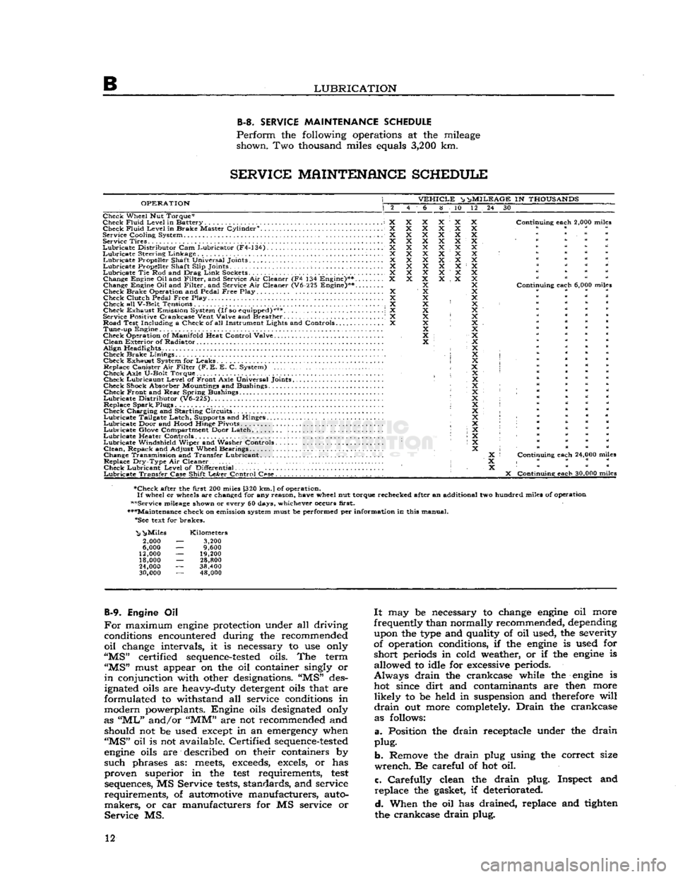
SERVICE
MAINTENANCE
SCHEDULE
Perform
the following operations at the mileage shown. Two thousand miles equals
3,200
km.
SERVICE
MAINTENANCE
SCHEDULE
OPERATION
VEHICLE
^ n>
MILEAGE
IN
THOUSANDS
6 8 10 12 24 30
Check Wheel Nut Torque*
Check
Fluid
Level
in Battery X Check
Fluid
Level
in Brake Master Cylinder0. X
Service
Cooling
System X Service Tires X
Lubricate
Distributor
Cam Lubricator (F4-134) X
Lubricate
Steering Linkage X
Lubricate
Propeller Shaft Universal Joints X
Lubricate
Propeller Shaft
Slip
Joints ; X
Lubricate
Tie Rod and Drag
Link
Sockets................................... X Change Engine
Oil
and
Filter,
and Service Air Cleaner (F4 134 Engine)** X
Change Engine Oil and
Filter,
and Service Air Cleaner (V6-225 Engine)**....
Check Brake Operation and Pedal
Free
Play X Check
Clutch
Pedal
Free
Play. .... X
Check all
V-Belt
Tensions X
Check Exhaust Emission System
(If
so equipped)*** \ X
Service Positive
Crankcase
Vent
Valve
and Breather . .' X
Road Test
Including
a Check of all Instrument
Lights
and Controls X Tune-up Engine
Check Operation of
Manifold
Heat
Control
Valve
Clean
Exterior of Radiator
Align
Headlights • Check Brake
Linings
,
Check Exhaust System for Leaks Replace Canister Air
Filter
(F. E. E. C. System)
Check
Axle
U-Bolt
Torque. Check Lubricaunt
Level
of Front
Axle
Universal Joints
Check Shock Absorber Mountings and Bushings Check Front and
Rear
Spring Bushings
Lubricate
Distributor
(V6-225).
Replace Spark, Plugs
Check Charging and Starting Circuits
Lubricate
Tailgate Latch, Supports and Hinges.
Lubricate
Door and
Hood
Hinge Pivots ;
Lubricate
Glove Compartment Door Latch
Lubricate
Heater Controls •
Lubricate
Windshield
Wiper and Washer Controls
Clean,
Repack and
Adjust
Wheel Bearings
Change Transmission and Transfer Lubricant. .
Replace
Dry-Type
Air Cleaner • Check Lubricant
Level
of
Differential
Lubricate
Transfer
Case
Shift
LeArer
Control
C«se.
. , . . . . . . . .
Continuing
each
2,000 miles
Continuing
each
6,000 miles
Continuing
each
24,000 miles
X
Continuing
each
30,000 miles
•Check after the
first
200 miles [320
km.
J
of operation.
If
wheel or wheels are changed for any
reason,
have
wheel nut torque rechecked after an additional two hundred miles of operation
••Service mileage shown or every 60 days, whichever occurs
first.
•••Maintenance check on emission system must be performed per
information
in this manual. "See text for brakes.
"Nj
^Miles
2,000
6,000
12,000
18,000
24,000
30,000
Kilometers
3,200
9,600
19,200
28,800
38,400 48,000
B-9.
Engine Oil
For
maximum
engine
protection under all driving conditions encountered during the recommended
oil
change intervals, it is necessary to use only
"MS"
certified
sequence-tested
oils. The term
"MS"
must appear on the oil container singly or
in
conjunction with other designations. "MS" des
ignated oils are heavy-duty detergent oils that are
formulated to withstand all service conditions in
modern powerplants. Engine oils designated only
as
"ML"
and/or
"MM"
are not recommended and should not be used except in an emergency when
"MS"
oil is not available. Certified
sequence-tested
engine
oils are described on their containers by
such
phrases as:
meets,
exceeds,
excels, or has
proven superior in the
test
requirements,
test
sequences, MS Service
tests,
standards, and service
requirements,
of automotive manufacturers, auto
makers,
or car manufacturers for MS service or
Service
MS.
It
may be necessary to change
engine
oil more
frequently than normally recommended, depending upon the type and quality of oil used, the severity
of operation conditions, if the
engine
is used for
short
periods in cold weather, or if the
engine
is allowed to idle for excessive periods.
Always
drain
the crankcase while the
engine
is hot since
dirt
and contaminants are then more
likely
to be held in suspension and therefore
will
drain
out more completely.
Drain
the crankcase as follows:
a.
Position the
drain
receptacle under the
drain
plug.
b.
Remove the
drain
plug using the correct size
wrench.
Be careful of hot oil.
c.
Carefully
clean the
drain
plug. Inspect and
replace
the gasket, if deteriorated.
d.
When the oil has drained, replace and tighten
the crankcase
drain
plug. 12
Page 17 of 376
'Jeep'
UNIVERSAL SERIES SERVICE
MANUAL
B
Reinstall
the axle shafts, and
refill
the housings to
plug level using the universal joint lubricant
specified in
Lubrication
Specifications.
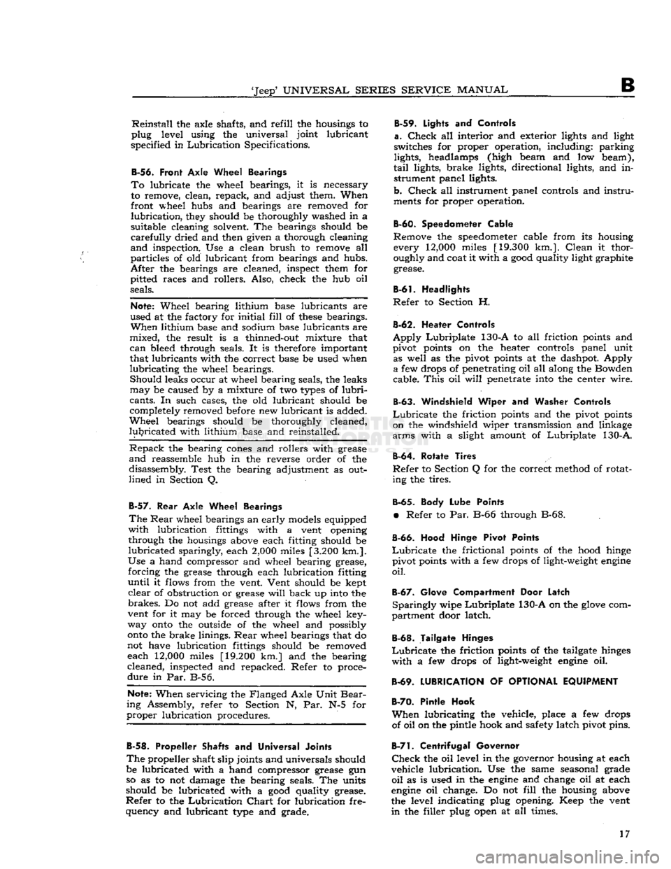
B-56.
Front
Axle Wheel Bearings
To
lubricate the wheel bearings, it is necessary
to remove, clean, repack, and adjust them. When
front wheel hubs and bearings are removed for
lubrication,
they should be thoroughly washed in a
suitable cleaning solvent. The bearings should be
carefully
dried and then given a thorough cleaning
and
inspection. Use a clean brush to remove all
particles
of old lubricant from bearings and hubs.
After
the bearings are cleaned, inspect them for
pitted races and rollers. Also, check the hub oil
seals.
Note:
Wheel bearing lithium base lubricants are
used at the factory for
initial
fill
of
these
bearings.
When
lithium base and sodium base lubricants are
mixed,
the result is a thinned-out mixture that
can
bleed through seals. It is therefore important
that lubricants with the correct base be used when
lubricating
the wheel bearings.
Should
leaks occur at wheel bearing seals, the leaks
may
be caused by a mixture of two
types
of
lubri
cants.
In such cases, the old lubricant should be
completely removed before new lubricant is added.
Wheel
bearings should be thoroughly cleaned,
lubricated
with lithium base and reinstalled.
Repack
the bearing
cones
and rollers with grease
and
reassemble hub in the reverse order of the
disassembly. Test the bearing adjustment as out
lined
in Section Q.
B-57.
Rear
Axle Wheel Bearings
The
Rear
wheel bearings an early models equipped
with
lubrication fittings with a vent opening
through the housings above each fitting should be
lubricated
sparingly, each
2,000
miles
[3.200
km.].
Use
a hand compressor and wheel bearing grease,
forcing
the grease through each lubrication fitting
until
it flows from the vent. Vent should be kept
clear
of obstruction or grease
will
back up into the
brakes.
Do not add grease after it flows from the
vent for it may be forced through the wheel key-
way
onto
the outside of the wheel and possibly
onto
the brake linings.
Rear
wheel bearings that do
not have lubrication fittings should be removed
each
12,000
miles
[19.200
km.] and the bearing
cleaned, inspected and repacked. Refer to proce
dure
in Par. B-56.
Note:
When servicing the Flanged Axle Unit
Bear
ing Assembly, refer to Section N, Par. N-5 for
proper
lubrication procedures.
B-58.
Propeller Shafts
and
Universal Joints
The
propeller shaft slip joints and universals should
be lubricated with a hand compressor grease gun so as to not damage the bearing seals. The units
should be lubricated with a
good
quality grease.
Refer
to the
Lubrication
Chart
for lubrication fre
quency and lubricant type and grade. B-59.
Lights
and
Controls
a.
Check
all interior and exterior lights and light
switches for proper operation, including: parking
lights, headlamps (high beam and low beam),
tail
lights, brake lights, directional lights, and in strument panel lights.
b.
Check
all instrument panel controls and
instru
ments for proper operation.
B-60.
Speedometer Cable
Remove the
speedometer
cable from its housing every
12,000
miles
[19.300
km.].
Clean
it thor
oughly and coat it with a
good
quality light graphite grease.
B-61.
Headlights
Refer
to Section H.
B-62.
Heater Controls
Apply
Lubriplate
130-A to all friction points and
pivot points on the heater controls panel unit as well as the pivot points at the dashpot. Apply
a
few drops of penetrating oil all along the Bowden
cable.
This
oil
will
penetrate into the center wire.
B-63.
Windshield Wiper and
Washer Controls
Lubricate
the friction points and the pivot points
on the windshield wiper transmission and linkage
arms
with a slight amount of
Lubriplate
130-A.
B-64.
Rotate Tires
Refer
to Section Q for the correct method of rotat ing the tires.
B-65.
Body Lube Points
•
Refer to Par. B-66 through B-68.
B-66.
Hood Hinge Pivot Points
Lubricate
the frictional points of the hood hinge
pivot points with a few drops of light-weight
engine
oil.
B-67.
Glove Compartment Door Latch
Sparingly
wipe
Lubriplate
130-A on the
glove
com
partment door latch.
B-68.
Tailgate Hinges
Lubricate
the friction points of the tailgate hinges
with
a few drops of light-weight
engine
oil.
B-69.
LUBRICATION
OF
OPTIONAL EQUIPMENT
B-70.
Pintle Hook
When
lubricating the vehicle, place a few drops of oil on the pintle hook and safety latch pivot pins.
B-7!.
Centrifugal Governor
Check
the oil level in the governor housing at each
vehicle lubrication. Use the same seasonal grade
oil
as is used in the
engine
and change oil at each
engine
oil change. Do not
fill
the housing above
the level indicating plug opening. Keep the vent
in
the filler plug open at all times. 17
Page 34 of 376
TUNE-UP
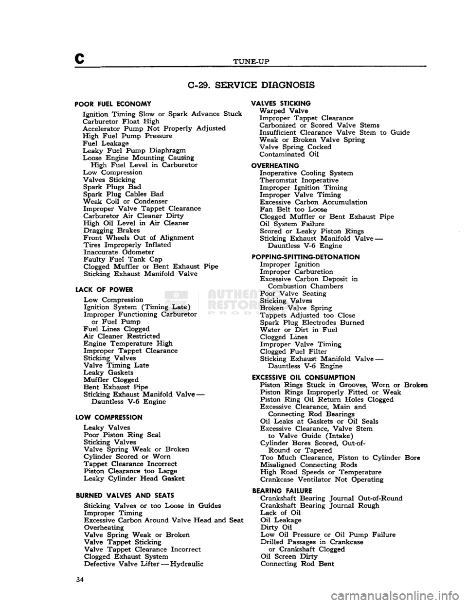
C-29.
SERVICE
DIAGNOSIS
POOR
FUEL ECONOMY Ignition Timing Slow or Spark Advance Stuck
Carburetor
Float High
Accelerator Pump Not Properly Adjusted High Fuel Pump Pressure
Fuel
Leakage
Leaky
Fuel Pump Diaphragm Loose Engine Mounting Causing High Fuel Level in Carburetor
Low
Compression
Valves Sticking
Spark
Plugs Bad
Spark
Plug Cables Bad
Weak
Coil
or Condenser Improper Valve Tappet Clearance
Carburetor
Air Cleaner Dirty
High Oil Level in Air Cleaner Dragging Brakes
Front
Wheels Out of Alignment
Tires
Improperly Inflated Inaccurate Odometer
Faulty
Fuel Tank Cap
Clogged
Muffler or Bent Exhaust Pipe Sticking Exhaust Manifold Valve
LACK
OF POWER
Low
Compression Ignition System (Timing Late)
Improper Functioning Carburetor
or Fuel Pump
Fuel
Lines
Clogged
Air
Cleaner Restricted Engine Temperature High Improper Tappet Clearance
Sticking Valves
Valve Timing Late
Leaky
Gaskets
Muffler
Clogged
Bent Exhaust Pipe Sticking Exhaust Manifold Valve —
Dauntless V-6 Engine
LOW
COMPRESSION
Leaky
Valves Poor Piston Ring Seal Sticking Valves
Valve Spring Weak or Broken
Cylinder
Scored or Worn
Tappet Clearance Incorrect Piston Clearance too Large
Leaky
Cylinder Head Gasket
BURNED
VALVES AND SEATS Sticking Valves or too Loose in Guides
Improper Timing
Excessive Carbon Around Valve Head and Seat Overheating
Valve Spring Weak or Broken
Valve Tappet Sticking
Valve Tappet Clearance Incorrect
Clogged
Exhaust System
Defective
Valve
Lifter
— Hydraulic
VALVES
STICKING
Warped Valve Improper Tappet Clearance Carbonized or Scored Valve
Stems
Insufficient Clearance Valve Stem to Guide
Weak or Broken Valve Spring Valve Spring Cocked Contaminated Oil
OVERHEATING
Inoperative Cooling System
Theromstat Inoperative Improper Ignition Timing
Improper Valve Timing
Excessive Carbon Accumulation
Fan
Belt too Loose
Clogged
Muffler or Bent Exhaust Pipe
Oil
System Failure Scored or Leaky Piston Rings
Sticking Exhaust Manifold Valve — Dauntless V-6 Engine
POPPING-SPITTING-DETONATION
Improper Ignition Improper Carburetion
Excessive Carbon
Deposit
in
Combustion Chambers
Poor Valve Seating Sticking Valves
Broken Valve Spring Tappets Adjusted too Close
Spark
Plug Electrodes Burned
Water or Dirt in Fuel
Clogged
Lines Improper Valve Timing
Clogged
Fuel Filter Sticking Exhaust Manifold Valve —
Dauntless V-6 Engine
EXCESSIVE
OIL CONSUMPTION Piston Rings Stuck in Grooves, Worn or Broken Piston Rings Improperly Fitted or Weak Piston Ring Oil Return
Holes
Clogged
Excessive Clearance, Main and
Connecting Rod Bearings
Oil
Leaks at Gaskets or Oil Seals
Excessive Clearance, Valve Stem
to Valve Guide (Intake)
Cylinder
Bores Scored, Out-of-
Round or Tapered
Too Much Clearance, Piston to Cylinder Bore
Misaligned Connecting Rods
High Road
Speeds
or Temperature
Crankcase
Ventilator Not Operating
BEARING
FAILURE
Crankshaft
Bearing Journal Out-of-Round
Crankshaft
Bearing Journal Rough
Lack
of Oil
Oil
Leakage
Dirty
Oil
Low
Oil Pressure or Oil Pump Failure
Drilled
Passages
in Crankcase or Crankshaft
Clogged
Oil
Screen Dirty
Connecting Rod Bent 34
Page 70 of 376
D
HURRICANE
F4
ENGINE
D-112.
SERVICE
DIAGNOSIS
Poor
Fuel
Economy Ignition Timing Slow or Spark Advance Stuck
Carburetor
Float High
Accelerator Pump Not Properly Adjusted
High
Fuel
Pump Pressure
Fuel
Leakage
Leaky
Fuel
Pump Diaphragm
Loose Engine Mounting Causing High
Fuel
Level
in
Carburetor
Low
Compression Valves Sticking
Spark
Plugs Bad
Spark
Plug Cables Bad Weak
Coil
or Condenser Improper Valve Tappet Clearance
Carburetor
Air Cleaner Dirty
High Oil Level in Air Cleaner Dragging Brakes
Front
Wheels Out of Alignment
Tires
Improperly Inflated Inaccurate Odometer
Faulty
Fuel
Tank
Cap
Clogged
Muffler or Bent Exhaust Pipe
Lack
of Power
Low
Compression Ignition System (Timing Late)
Improper Functioning Carburetor or
Fuel
Pump
Fuel
Lines
Clogged
Air
Cleaner Restricted
Engine Temperature High Improper Tappet Clearance
Sticking Valves Valve Timing Late
Leaky
Gaskets
Muffler
Clogged
Bent Exhaust Pipe
Defective
Spark Plugs—Clean or Replace
Defective
Breaker Points—Replace
Points
Incorrect Breaker Point Gap—Reset
Points
Defective
Condenser or Coil—Replace
Loose Electrical Connections—Locate and Tighten
Broken Valve Spring—Replace Spring Broken Piston or Rings—Replace
Defective
Head Gasket—Replace Gasket
Cracked
Distributor Cap—Replace Cap
Low
Compression
Leaky
Valves
Poor Piston Ring Seal Sticking Valves
Valve Spring Weak or Broken
Cylinder
Scored or Worn
Tappet Clearance Incorrect
Piston Clearance too Large
Leaky
Cylinder Head Gasket
Burned Valves and
Seats
Sticking Valves or too Loose in Guides Improper Timing
Excessive Carbon Around Valve Head and Seat Overheating
Valve Spring Weak or Broken Burned Valves and Seats—Continued
Valve Tappet Sticking
Valve Tappet Clearance Incorrect
Clogged
Exhaust System
Valves Sticking Warped Valve Improper Tappet Clearance
Carbonized or Scored Valve
Stems
Insufficient Clearance Valve Stem to Guide
Weak or Broken Valve Spring Valve Spring Cocked Contaminated Oil
Overheating Inoperative Cooling System
Thermostat Inoperative Improper Ignition Timing
Improper Valve Timing
Excessive Carbon Accumulation
Fan
Belt too Loose
Clogged
Muffler or Bent Exhaust Pipe
Oil
System Failure
Scored or Leaky Piston Rings
Popping-Spitting-Detonation
Improper Ignition
Improper Carburetion
Excessive Carbon
Deposit
in Combustion
Cham
bers
Poor Valve Seating Sticking Valves
Broken Valve Spring Tappets Adjusted too Close
Spark
Plug Electrodes Burned
Water or Dirt in
Fuel
Clogged
Lines Improper Valve Timing
Excessive Oil Comsumption Piston Rings Stuck in Grooves, Worn or Broken Piston Rings Improperly Fitted or Weak Piston Ring Oil Return
Holes
Clogged
Excessive Clearance, Main and Connecting Rod
Bearings
Oil
Leaks at Gaskets or Oil Seals
Excessive Clearance, Valve Stem to Valve Guide (Intake)
Cylinder
Bores Scored, Out-of-Round or Tapered Too Much Clearance, Piston to Cylinder Bore
Misaligned Connecting Rods
High Road
Speeds
or Temperature
Crankcase
Ventilator Not Operating
Bearing Failure
Crankshaft
Bearing Journal Out-of-Round
Crankshaft
Bearing Journal Rough
Lack
of Oil
Oil
Leakage
Dirty
Oil
Low
Oil Pressure or Oil Pump Failure
Drilled
Passages
in Crankcase or Crankshaft
Clogged
Oil
Screen Dirty Connecting Rod Bent 70
Page 134 of 376

E
FUEL
SYSTEM
E-78. SERVICE DIHGNOSIS
Symptoms Probable Remedy
Excessive
Fuel
Consumption:
Tires
improperly inflated Inflate
Brakes
drag Adjust
Engine
operates too cold Check thermostat
Heat control valve inoperative Check thermostatic spring
Leak
in fuel line Check all connections
Carburetor
float level high. See
"Carburetor"
section
Accelerator pump not properly adjusted Adjust
Leaky
fuel pump diaphragm Replace
Loose
engine
mountings causing high carburetor fuel level Tighten Ignition timing slow or spark advance stuck See "Distributor" section
Low
compression. Check valve tappet clearance
Air
cleaner dirty
.
Remove and clean
Engine
Hesitates on Acceleration: Accelerator pump
does
not function perfectly.
...................
.Replace piston and rod or adjust
Carburetor
float level. ... .Adjust
Spark
plugs Replace or clean and adjust
Low
compression Check valves
Distributor
points—dirty or pitted Replace
Weak
condenser or coil Replace
Carburetor
jets restricted Remove and clean
Excessive
engine
heat See "Engine" section
Engine
Stalls—Won't Idle:
Improper
condition of carburetor See
"Carburetor"
section
Low
speed
jet restricted Remove and clean
Dirty
fuel sediment bowl screen Remove and clean
Air
cleaner dirty Remove and clean
Leaky
manifold or gasket Replace
Fuel
pump diaphragm porous. Replace
Loose carburetor. Tighten
flange
nuts
Water
in fuel
Drain
and clean system
Improper
ignition. .See "Distributor" section
Spark
plugs Clean and adjust
Valves
sticking.
Grind
valves 134
Page 285 of 376

'Jeep'
UNIVERSAL
SERIES
SERVICE
MANUAL
M
M-19.
SERVICE
DIAGNOSIS
SYMPTOMS
PROBABLE
REMEDY
Hard Steering
Lack
of
Lubrication
Lubricate
Tires
Soft.
. Inflate
Tight
Steering. Adjust. See "Steering" Section
Low Speed Shimmy
or
Wheel Fight
Spring
Clips and Shackles Loose
Front
Axle Shifted Insufficient Toe-In
Improper
Caster
Steering System Loose or Worn
Twisted Axle
High Speed Shimmy
or
Wheel Fight
Check
Conditions Under "Low Speed Shimmy"
Tire
Pressures Low or not
Equal
Wheel Out of Balance
Wheel Runout
Radial
Runout of Tires
Wheel Camber
Front
Springs
Settled
or Broken
Bent Steering Knuckle
Arm..................
Shock Absorbers not Effective
Steering
Gear
Loose on Frame
Front
Springs too Flexible
Tramp
Wheels Unbalanced
Wandering
Improper
Toe-in
Broken
Front Spring Main
Leaf
Axle Shifted Loose Spring Shackles or Clips
Improper
Caster
Tire
Pressure Uneven
Tightness in Steering System
Loose Wheel Bearings
Front
Spring
Settled
or Broken
Axle
Noisy
on
Pull
Pinion and Ring
Gear
Adjusted too Tight
Pinion Bearings Rough.
Axle Noisy
on
Coast
Excessive Back
Lash
at Ring and Pinion Gears.
End
Play in Pinion Shaft. . . Rough Bearing.
Axle Noisy
on
Coast
and
Pull
Ring
and Pinion Adjusted too Tight
Pinion Set too
Deep
in Ring
Gear
Pinion Bearing Loose or Worn
Back Lash
Axle Shaft Universal Joint Worn
Axle Shaft Improperly Adjusted
Worn
Differential Pinion Washers
Worn
Propeller Shaft Universal Joints.
Readjust
or Replace
Broken
Spring Center Bolt
Adjust
Reset
Adjust
or Overhaul Steering
Gear,
Front Axle or
Steering Parts
Straighten or Adjust
Inflate
Balance
Straighten Mount Properly
Same on Both Wheels
Repair
or Replace
Straighten or Replace
Replace or Repair Tighten
Over
Lubricated
Check
and Balance
Adjust—Check
for Bent Steering Knuckle Arm Replace
Spring
Center Bolt Broken
Adjust
or Replace
Reset Inflate
Adjust
Adjust
Repair
or Replace
Readjust
Replace
Readjust
Readjust
Replace
Readjust Readjust
Readjust
or Replace
Replace
Readjust
Replace
Repair
Emergency
Where difficulty is experienced with front axle differential making the vehicle inoperative,
remove
axle driving
flanges.
This will allow bringing vehicle in under its own power. Be sure the transfer
case
shift lever is in the neutral
(disengaged)
position.
285
Page 316 of 376

o
STEERING SYSTEM
FIG.
0-3—FRONT
WHEEL
TOE-IN
1—
Toe-in
Angle
2—
Vertical
Line
In
the absence of a wheel aligning fixture, toe-in
may
be set by measuring
between
the front wheels
at the
edge
of the rim, at the flange or at the tire
tread
center. When making this adjustment the
wheels must be in a straight ahead position.
It
is highly important that toe-in be checked regu
larly
and if found to be out of adjustment, correc tion should be made immediately.
The
correct toe-in of
these
models is found in the
specifications at the end of this section.
0-8. Toe-in Adjustment
The
toe-in may be adjusted with a line or straight
edge
as the vehicle tread is the same in front and
rear.
To set the adjustment both tie rods must be
adjusted
as outlined below:
Set the tie rod end of the steering bell-crank at
right
angles with the front axle. Place a straight
edge
or line against the left
rear
wheel and left front wheel to determine if the wheel is in a straight
ahead
position. If the front wheel tire
does
not touch the straight
edge
at both the front and
rear,
it
will
be necessary to adjust the left tie rod by loosening the clamps on each end and turning the
rod
until the tire touches the straight
edge.
Check
the right hand side in the same manner, ad
justing
the tie rod if necessary, making sure that the bell-crank remains at right angles to the axle.
When
it is determined that the front wheels are in the straight ahead position, set the toe-in by short
ening each tie rod approximately one-half
turn.
0-9.
Front
Wheel
Camber
The
purpose of camber Fig. 0-4, is to more nearly
place the weight of the vehicle over the tire con tact on the road to facilitate
ease
of steering.
The
result of excessive camber is irregular wear of
tires on outside shoulders and is usually caused by
bent axle parts.
The
result of negative or reverse camber, if ex
cessive,
will
be
hard
steering and possibly a wan
dering
condition.
Tires
will
also wear on inside shoulders. Negative camber is usually caused by
excessive wear or
looseness
of front wheel bearings, axle parts or the result of a sagging axle.
Unequal
camber may cause any or a combination
of the following conditions: unstable steering, wan- 11894-
FIG.
0-4—WHEEL CAMBER
1—Vertical
Line
2—Camber Angle
dering,
kick-back or road shock, shimmy or exces
sive tire wear. The cause of unequal camber is usu
ally
a bent steering knuckle or axle end.
Correct
wheel camber is set in the axle at the time
of manufacture and cannot be altered by any ad
justment. It is important that the camber be the same on both front wheels. Heating of any of
these
parts
to facilitate straightening usually destroys
the heat treatment given them at the factory.
Cold
bending may cause a fracture of the steel and is also
unsafe. Replacement with new parts is recom mended rather than any straightening of damaged
parts.
O-10.
Axle
Caster Caster
angle is established in the axle design by
tilting the top of the kingpin toward the
rear
and
the
bottom
of the kingpin forward so that an
imaginary
line through the center of the kingpin
would strike the ground at a point ahead of the point of tire contact.
FIG.
0-5—AXLE
CASTER
1—
Vertical
Line
2—
Caster
Angle
316