1953 JEEP DJ oil change
[x] Cancel search: oil changePage 18 of 376
B
LUBRICATION
B-72.
Powr-Lok
or Trac-Lok
Differential
Refer
to Par. B-53.
B-73.
PARTS
REQUIRING
NO
LUBRICATION
B-74.
Water Pump Bearing,
Clutch
Release
Bearing
The
water pump and clutch release bearings are
prelubricated
for life when manufactured and cannot be relubricated.
B-7S.
Starter
Motor
Bearings
The
starting motor bearings are lubricated at assembly to last
between
normal rebuild periods.
B-76.
Alternator Bearings
The
alternator bearings are lubricated at assembly
and
require no further lubrication.
B-77.
Springs
The
vehicle springs should not be lubricated. At assembly the leaves are coated with a long-lasting
special
lubricant which is designed to last the life
of the springs. Spraying with the usual mixture of
oil
and kerosene has a tendency to wash this
lubri
cant
from
between
the leaves, making it necessary
to relubricate
often
to eliminate squeaking.
B-78.
Shock Absorbers
Hydraulic
direct-action shock absorbers are per manently sealed and require no periodic
lubrica
tion service. Shock absorber mounting bushings
are
not to be lubricated.
B-79.
LUBRICATION
REQUIREMENTS
FOR
OFF-HIGHWAY
OPERATION
Adequate lubrication
becomes
increasingly im portant when vehicles are used in off-highway
operation. Under
these
conditions all operating
parts
of both the
engine
and chassis are subjected
to unusual pressures. At the same time such operation is usually under abnormal dust and
dirt
conditions making additional precautions neces
sary.
The importance of correct lubrication for
the conditions of operation cannot be overestimated.
B-80.
Engine
Oil
It
is important, that the oil in a new or rebuilt
engine
be changed after the first
eight
or ten hours
of operation, and for heavy, dusty work, every 50
hours
thereafter. Watch the condition of the oil closely and change it immediately if it appears to
be contaminated.
i-Il.
Engine
Oil
Filter
Replace
the oil filter at the end of the first 100
hours
of service. Under extreme operating con ditions, more frequent replacement may be re
quired.
The condition of the oil is a reliable
indicator
of the condition of the filter element.
If
the oil
becomes
discolored and shows evidence
of contamination, change the filter without delay.
(Refer
to
Par.
B-10, B-ll for the correct procedure
for replacing the oil filter.)
B-82.
Air Cleaner
Care
of the air cleaner is extremely vital to the life of the engine. Pay particular attention to the
amount of dust and
dirt
in the air taken into the
engine
through the air cleaner. When dust is not
noticeable in the air, service the air cleaner each scheduled maintenance period. Whenever the air is
noticeably dusty (for example when the vehicle is
driven
on secondary roads or through fields) then
service the air cleaner more frequently. Under extreme continually dusty and dirty conditions
where the vehicle operates in clouds of dust and
dirt,
service the air cleaner daily. (Refer to Par.
B-24
thru
B-26 for service procedures.)
B-83.
Chassis
Lubrication
The
period of lubrication depends entirely upon the type of work being done. Using the specified
interval
given in the Service Maintenance Schedule as a guide, lubricate at safe intervals required for
the particular type of operation. Under extremely
dusty conditions lubricate
these
points daily. Be
sure
to force enough lubricant into each fitting to force out the old lubricant which might be con
taminated with grit and which would cause
rapid
wear
if allowed to remain.
Do not place lubricant on the various
ball
and socket joints or pivot points of the lift linkage as
dirt
will
accumulate to form an abrasive mix
ture.
It is
best
to simply wipe
these
parts clean
with
a cloth.
B-84.
Front
Axle
Shaft Universal Joints
For
off-highway use remove the universal joints twice yearly, thoroughly clean both the housings
and
joints with a suitable solvent, and
refill
the
housings to the
fill
plug opening levels with the
correct
lubricant as given in the
Lubrication
Specifications.
B-85.
Transmission and Transfer
Case
The
combined capacity of the two housings is
small
for economy, making it important that the
lubricant
be changed at regular intervals. For off-highway use
drain
both housings every 300
hours
of operation and
refill
to the
fill
plug opening
levels. Refer to B-35 through B-37 when changing
lubricant.
B-86.
Front and
Rear
Axle
Differentials
Because of the higher pressure developed in the
axle assemblies with heavy duty operation,
drain,
flush,
and
refill
the differential assemblies each 300 hours of operation. Use only flushing oil or light
engine
oil to clean out the housings (except
Powr-Lok
and
Trac-Lok
differentials). Refer to
Par.
B-52 and B-53 for draining and flushing
differential.
18
Page 30 of 376
c
TUNE-UP
meter during this
test
Connect the red lead
tc*
dis
tributor
primary
lead at the coil as shown in Fig.
C-21.
Connect black lead to the ground.
Turn
ignition switch on; with
engine
stopped, observe
dwell
meter. If the meter reads zero,
crank
the
engine
a fraction of a revolution to
close
the
breaker
points.
Distributor
resistance is normal, if dwell meter
pointer is within range of
black
bar. Distributor resistance is high, if
dwell
meter pointer is not
within
the black bar.
Remove test lead from
distri
butor terminal of coil and
connect
to
each
of the
following points to determine
where
the excessive resistance is:
Distributor
primary
terminal
Distributor
primary
terminal in the distributor
Breaker
point bracket
Ground
side of points
Distributor
housing
Where
a noticeable change occurs in the meter
reading
in
these
steps, make the necessary correc
tion and repeat the
test.
C-l 7. Distributor
Point
Dwell
Using
a dwell tester, connect red
lead
to the
distri
butor terminal at coil. Connect black lead to
ground.
Set selector switch to the number of
cylin
ders in the
engine
being tested. Operate
engine
speed at specified rpm. and
note
readings. Cam
dwell
angle must be 30° for the Dauntless V-6
Delco equipped engine, 29° ±: 3° Prestolite equipped
engine
and 42° for the
Hurricane
F4 engine. If the dwell reading is not to specifications,
trouble could be improper point spacing, point
rubbing,
defective block or breaker arm, or mis
aligned and worn distributor cam.
Adjust
dwell
as shown in Fig. C-14 for the Delco equipped
Dauntless V-6 engine. For cam dwell adjustment
of the Prestolite equipped V6 and
Hurricane
F4 engine, refer to Par. C-10,
step
a.
Dwell
variation is determined by noting any
dwell
change as the
engine
is operated at different
speeds.
Excessive
variation indicates a change in point opening that can result from shaft or bushing wear,
or
from the distributor plate shifting because of
wear
or
looseness.
Measure
dwell variation at idle speed, using same
test
hookup for checking dwell. Increase speed to 1750 rpm.;
note
dwell reading.
Then
slowly reduce
speed to idle while observing dwell meter. Dwell
variation
should not exceed 3°. If dwell variation
exceeds
3°
between
idle speed and 1750 rpm.,
probable wear in the distributor shaft, bushings, or
breaker
plate is indicated. Distributor should then be checked more thoroughly.
C-l8. Check Ignition Wires
and
Connections
Examine
and clean the insulation on all ignition
wires
and check all connections. Wires should be
firm,
flexible, and free from roughness and minute
cracks.
Bend wires to check for brittle,
cracked,
or
loose
insulation. Since defective insulation
will
per
mit
crossfiring or missing of the engine, defective
wires
should be replaced.
C-l9. Test Ignition
Cables
To
remove cables from
spark
plugs, use
Spark
Plug
Cable
Remover
Tool
W-274.
Twist
the
boot
slightly to break the seal and, grasping the rubber
protector
boot,
lift straight up with a steady even
pull.
Do not grasp the cable and
jerk
the cable off; this
will
damage the cables. Do not use a probe
on
these
wires; puncturing them may cause a
separation in the conductor. To remove ignition cables from the distributor cap or coil tower,
loosen
the nipple first, then grasp the upper part of the nipple and the cable and gently
pull
straight up.
Test
the cable with an ohmmeter. Resistance value
per
foot
is
3000-7000
ohms. The ignition cables
can
be checked for
circuit
continuity by removing
the cable from the
spark
plug and holding the cable
end Vi" [6,35 mm.] from the engine. A strong
spark
indicates
good
conductor continuity.
When
connecting the cable to the
spark
plug, be
certain
a
good
connection is made and that the
protector
boot
fits tight on the
spark
plug. A
partially
seated cable creates an additional gap in
the
circuit
and the resulting
spark
jump
will
cause
terminal
corrosion and cable damage.
C-20. Coil
When
an ignition coil is suspected of being defec tive, it should be checked on the car. A coil may
break
down after it has reached operating tempera
ture.
It is important that the coil be at operating
temperature when
tests
are made.
Note:
The ignition coil and ballast resistor for the
V-6
engine
must be of the same manufacturer.
Ballast
resistors and ignition coils of one manufac
turer
are interchangeable with both units of the
other.
C-21.
Service Air
Cleaner
Refer
to Par.
B-2 2
for the correct service of the
air
cleaner.
C-22.
Check Fuel Lines and
Screens
Check
all fuel line connections to guard against
leakage.
Check
fuel pump filter F4
engine
and
fuel
line filter V-6 engine. Replace fuel filter if
necessary.
C-23. Check Fuel Pump a.
Fuel
pump pressure is important, for low pres
sure
will
seriously affect
engine
operation and high
pressure
will
cause excessive fuel consumption and
possibly flood the carburetor. Should there be any doubt of normal operation, check the pressure with
a
gauge
as shown in Fig.
C-2 2.
The minimum and
maximum
allowable pressures are 2% to 3% lbs. [0,176 a
0,264
kg-cm2], for the
Hurricane
F4 en
gine.
Fuel
pump pressure at carburetor (inlet) on
the Dauntless V6-225
engine
should be 3% lbs.
[0,264
kg-cm2] minimum at specified
R.P.M.
idle
with
the vapor
return
hose
squeezed off.
With
the
vapor
return
hose
open pump pressure should be
2
V2
lbs. [0,176 kg-cm2] minimum.
b.
Test for volume, as a pump may build up suffi
cient pressure but
fail
to produce sufficient volume.
Turn
down the carburetor fuel line fitting on the
pump and with the tank line connected, pump out
30
Page 49 of 376
'Jeep'
UNIVERSAL SERIES
SERVICE
MANUAL
D
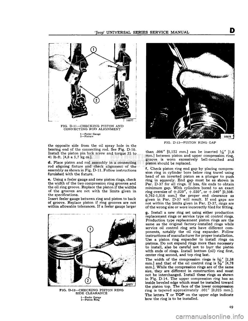
FIG.
D-ll—CHECKING PISTON
AND
CONNECTING
ROD
ALIGNMENT 1—
Feeler
Gauge
2—
Fixture
the
opposite
side from the oil spray
hole
in the
bearing
end of the connecting rod. See Fig. D-10.
Install
the piston pin lock screw and torque 35 to
41 lb-ft. [4,8 a 5,7 kg-m.].
d.
Place piston and rod assembly in a connecting
rod
aligning fixture and check alignment of the
assembly as shown in
Fig. D-ll.
Follow instructions
furnished
with the fixture.
e. Using a feeler
gauge
and new piston rings, check the width of the two compression ring
grooves
and
the oil ring groove. Replace the piston if the widths of the
grooves
are not with the limits given in
the specifications.
Insert
feeler
gauge
between
ring and piston to back
of groove. Replace piston if ring
grooves
are not
within
allowable tolerances. If a feeler
gauge
larger
FIG.
D-l 2—CHECKING PISTON RING
SIDE
CLEARANCE
1—
Feeler
Gauge
2—
Piston
Ring
FIG.
D-13—PISTON
RING
GAP
than
.006" [0,152 mm.] can be inserted
J^6"
[1,6
mm.]
between
piston and upper compression
ring,
groove
is worn excessively bell-mouthed and
piston should be replaced.
f.
Check
piston ring end gap by placing compres sion ring in cylinder bore below ring travel using head of an inverted piston as a plunger to push
ring
in squarely. End gap must be as shown in
Par.
D-37 for all rings. If less, file ends to obtain
minimum
gap.
With
cylinders bored to an exact
ring
oversize of
+.020", +.030",
or
+.040"
[0,508-
0,762-1,016
mm.] the proper end clearance as given in Par. D-37
will
result. If end
gaps
are
not within the limits given in Par.
D-3
7, rings are
of the wrong size or were incorrectly filed for fitting.
g.
Install
a new ring set using either production replacement rings or service type oil control rings.
Production
type replacement piston rings are the
same as the original factory-installed rings while
service oil control ring
sets
have different com
ponents, notably the oil ring expander. Follow
instructions of
manufacturer
for proper installation.
Use
a piston ring expander to install rings on pistons. Do not expand rings more than necessary
to install, also be careful not to
burr
the piston
with
ends of rings.
Install
bottom
(oil) ring first, center ring second, and top ring last.
The
width of the compression rings is [2,38
mm.] and that of the oil control ring is f^" [4,78
mm.].
While the compression rings are of the same
size, they are different in construction and must
not be interchanged.
Install
these
rings as shown
in
Fig. D-14. The upper compression ring has an
inside beveled
edge
which must be installed toward
the piston top. The face of the lower compression
ring
is tapered approximately .001" [0,025 mm.].
The
letters T or TOP on the upper
edge
indicate
how the ring is to be installed. 49
Page 52 of 376
D
HURRICANE
F4
ENGINE
10442
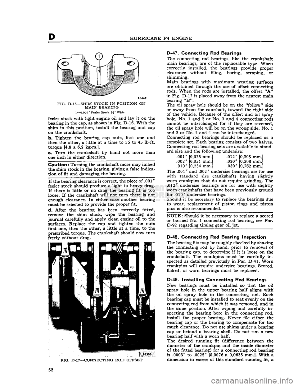
FIG.
D-l6—SHIM
STOCK
IN
POSITION
ON
MAIN
BEARING
1—0.001"
Feeler Stock H' Wide feeler stock with light
engine
oil and lay it on the
bearing
in the cap, as shown in
Fig.
D-16.
With
the
shim
in this position, install the bearing and cap
on the crankshaft.
b.
Tighten the bearing cap nuts, first one and
then the other, a little at a time to 35 to 45 lb-ft. torque [4,8 a 6,2 kg-m.].
c.
Turn
the crankshaft by hand not more than
one inch in either direction.
Caution:
Turning
the crankshaft more may imbed the shim stock in the bearing, giving a false indica
tion of fit and damaging the bearing.
If
the bearing clearance is correct, the piece of .001"
feeler stock should produce a light to heavy drag.
If
there is little or no drag the bearing fit is too
loose.
If the crankshaft
will
not
turn
there is not
enough clearance. In either case another bearing must be selected to provide the proper fit.
d.
After the bearing has been correctly fitted, remove the shim stock, wipe the bearing and
journal
carefully and apply clean
engine
oil to the
surfaces.
Replace the cap and tighten the nuts first one, then the other, a little at a time, to the
prescribed
torque. The crankshaft should now
turn
freely without drag.
FIG.
D-l
7—CONNECTING
ROD
OFFSET
D-47.
Connecting Rod Bearings
The
connecting rod bearings, like the crankshaft
main
bearings, are of the replaceable type. When
correctly
installed, the bearings provide proper
clearance
without filing, boring, scraping, or
shimming.
Main
bearings with maximum wearing surfaces
are
obtained through the use of
offset
connecting
rods.
When the rods are installed, the
offset
"A"
in
Fig. D-l7 is placed away from the nearest main
bearing
"B".
The
oil spray
hole
should be on the "follow" side
or
away from the camshaft, toward the right side
of the vehicle. Because of the
offset
and oil spray
hole, No. 1 and 2 or No. 3 and 4 connecting rods cannot be interchanged for if they are reversed,
the oil spray
hole
will
be on the wrong side. No. 1
and
3 or No. 2 and 4 can be interchanged.
Connecting
rod bearings should be replaced as a complete set.
Each
bearing consists of two halves.
Connecting
rod bearing
sets
are available in stand
ard
size and the following undersize:
.001" [0,025 mm.] .012" [0,305 mm.]
.002"
[0,051
mm.] .020" [0,508 mm.] .010"
[0,254
mm.] .030" [0,762 mm.]
The
.001" and .002" undersize bearings are for use
with
standard size crankshafts having slightly
worn
crankpins that do not require grinding. The .012" undersize bearings are for use with slightly
worn
crankshafts that have been previously ground for .010" undersize bearings.
Should
it be necessary to replace the bearings due to wear, replacement of piston rings and piston
pins is also recommended.
NOTE:
Should it be necessary to replace a scored
or
burned No. 1 connecting rod bearing, see Par. D-92 regarding timing gear oil jet.
D-48.
Connecting Rod Bearing Inspection
The
bearing fits may be roughly checked by shaking the connecting rod by hand,
prior
to removal of
the bearing cap, to determine if it is
loose
on the
crankshaft.
The crankpins must be carefully in
spected as detailed previously in Par. D-41.
Worn
crankpins
will
require undersize bearings. Scored,
flaked,
or
worn bearings must be replaced.
D-49.
Installing Connecting Rod Bearings
New bearings must be installed so that the oil
spray
hole
in the upper bearing
half
aligns with
the oil spray
hole
in the connecting rod.
Each
bearing
cap must be installed to seat evenly on the connecting rod from which it was removed, and in
the same position. After wiping and carefully in specting the bearing bore in the connecting rod,
install
the proper bearing. Never file either the
bearing
cap or the bearing to compensate for too
much
clearance. Do not use shims under a bearing
cap or behind a bearing shell. Do not run a new
bearing
half
with a worn half.
The
desired running fit (difference
between
the diameter of the
crankpin
and the inside diameter
of the fitted bearing) for a connecting rod bearing
is .0003" to .0025"
[0,0076
a
0,0635
mm.].
With
a dimension in
excess
of this standard running fit, a 52
Page 53 of 376
'Jeep'
UNIVERSAL
SERIES
SERVICE
MANUAL
D
satisfactory bearing replacement cannot be made
and
it
will
be necessary to regrind the crankshaft.
Install
the bearing lower
half
and the connecting
rod
cap and draw the cap bolt nuts down equally
and
only slightly tight. Move the connecting rod
endwise, one way or the other, on the crankshaft to be sure the bearing is not tight.
Pull
the nuts tighter, first one then the other, a little at a time,
and
keep trying the fit of the rod on the crankshaft by hand until the recommended torque of 35 to 45 lb-ft. [4,8 a 6,2 kg-m.] is reached. If the
bearings are of the correct size, and have been
properly
lubricated with light
engine
oil before in
stallation,
the connecting rod should be easy to
slide back and forth parallel to the
crankpin.
If
the connecting rod is tight on the crankshaft, a
larger
bearing is required. If there is no binding
or
tightness, it is
still
necessary to check clearance
to guard against too
loose
a fit. The use of "Plasti
gage"
or shim stock of the proper size to measure .001" [0,025 mm.] clearance is recommended for
checking
connecting rod bearing clearances.
This
is the same material recommended for checking
crankshaft
main bearings and the method of check
ing is
similar.
Refer to
Par.
D-45 or D-46. Connect
ing rod bearings are fitted to the same clearance as the main bearings but the torque specified for con
necting rod cap
bolts
is different.
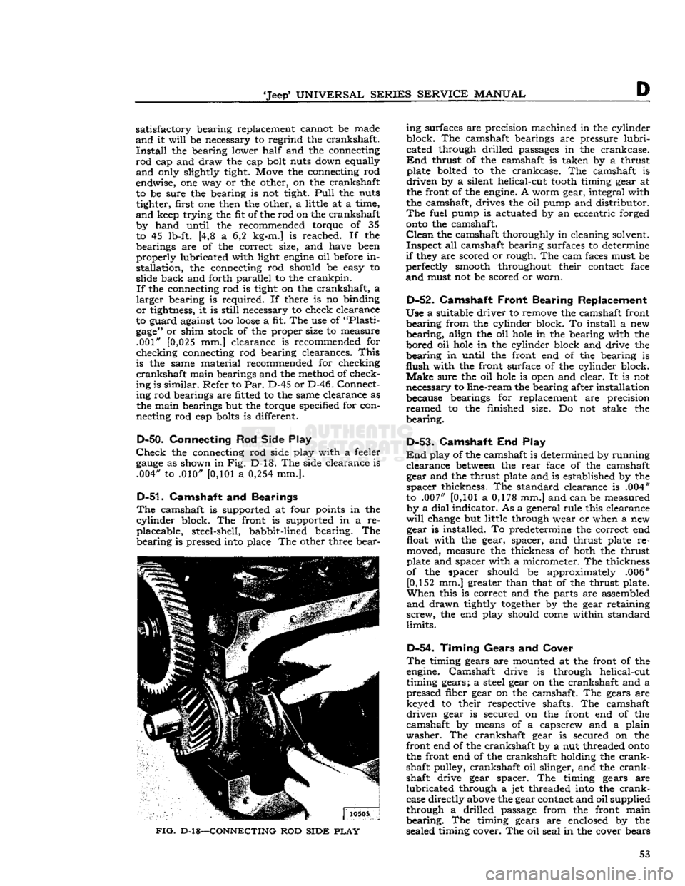
D-50.
Connecting
Rod
Side Play
Check
the connecting rod side play with a feeler
gauge
as shown in Fig. D-l8. The side clearance is .004" to .010"
[0,101
a
0,254
mm.].
D-51.
Camshaft and Bearings
The
camshaft is supported at four points in the
cylinder
block. The front is supported in a re placeable, steel-shell, babbit-lined bearing. The
bearing
is pressed into place The other three bear-
FIG.
D-18—CONNECTING
ROD
SIDE
PLAY
ing surfaces are precision machined in the cylinder
block. The camshaft bearings are pressure
lubri
cated through drilled passages in the crankcase.
End
thrust of the camshaft is taken by a thrust plate bolted to the crankcase. The camshaft is
driven
by a silent helical-cut
tooth
timing gear at
the front of the engine. A worm gear, integral with
the camshaft, drives the oil pump and distributor.
The
fuel pump is actuated by an eccentric forged
onto
the camshaft.
Clean
the camshaft thoroughly in cleaning solvent.
Inspect
all camshaft bearing surfaces to determine
if
they are scored or rough. The cam faces must be
perfectly smooth throughout their contact face
and
must not be scored or worn.
D-52.
Camshaft
Front Bearing Replacement
Use
a suitable driver to remove the camshaft front
bearing
from the cylinder block. To install a new
bearing,
align the oil
hole
in the bearing with the
bored oil
hole
in the cylinder block and drive the
bearing
in until the front end of the bearing is
flush
with the front surface of the cylinder block.
Make
sure the oil
hole
is open and clear. It is not
necessary to line-ream the bearing after installation because bearings for replacement are precision
reamed
to the finished size. Do not stake the
bearing.
D-53-
Camshaft End Play
End
play of the camshaft is determined by running
clearance
between
the
rear
face of the camshaft gear and the thrust plate and is established by the
spacer
thickness. The standard clearance is .004"
to .007"
[0,101
a 0,178 mm.] and can be measured by a
dial
indicator. As a general rule this clearance
will
change but little through wear or when a new gear is installed. To predetermine the correct end
float with the gear, spacer, and thrust plate re
moved, measure the thickness of both the thrust
plate and spacer with a micrometer. The thickness
of the spacer should be approximately .006" [0,152 mm.] greater than that of the thrust plate.
When
this is correct and the parts are assembled
and
drawn tightly
together
by the gear retaining
screw,
the end play should
come
within standard
limits.
D-54.
Timing Gears
and
Cover
The
timing gears are mounted at the front of the
engine. Camshaft drive is through helical-cut
timing gears; a steel gear on the crankshaft and a
pressed fiber gear on the camshaft. The gears are keyed to their respective shafts. The camshaft
driven
gear is secured on the front end of the
camshaft by means of a capscrew and a plain
washer.
The crankshaft gear is secured on the
front end of the crankshaft by a nut threaded
onto
the front end of the crankshaft holding the
crank
shaft pulley, crankshaft oil slinger, and the
crank
shaft drive gear spacer. The timing gears are
lubricated
through a jet threaded into the
crank
case directly above the gear contact and oil supplied
through a drilled passage from the front main
bearing.
The timing gears are enclosed by the
sealed timing cover. The oil seal in the cover bears 53
Page 54 of 376
D
HURRICANE
F4
ENGINE
against the hub of the crankshaft pulley.
Timing
gears are accessible for inspection or replacement
with
the
engine
installed in the vehicle after re moving the radiator, belt drive pulley, and timing
cover.
Should
it be necessary to replace the timing gears, attention must be given to the end float of both
the camshaft and crankshaft and to the running
clearance
of both gears. It is also advisable to
check
both the oil jet and oil passage to the
crank
shaft front bearing to be sure that they are clear.
D-55.
Inspection and
Repair
Check
the general condition of both gears and
inspect for evidence of excessive wear. Replace
excessively worn or damaged gears. Inspect the
cover and replace if bent or damaged. It is recom mended that the crankshaft oil seal in the cover
be replaced when the cover is removed to ensure a
good
seal around the crankshaft. To replace this
seal
with the
engine
in the vehicle
requires
removing
the radiator and water pump.
D-56.
Valves, Springs, and Guides
The
exhaust valves seat on the top of the cylinder
block
with the
stems
extending down through
replaceable valve guides. The exhaust valves are actuated by the camshaft through exhaust valve
tappets. The exhaust valve springs are assembled
and
locked on the lower end of the exhaust valve
stems. The retaining locks are the split type, which
fit in a recess on the valve
stems
and into the taper
in
the valve spring retainers.
Adjustment
of exhaust valves is by means of the
adjusting
screw threaded into the upper end of the
exhaust valve tappets. An exhaust valve rotator used as a valve spring retainer is installed on the
lower end of the exhaust valve.
This
valve rotator,
known
as "Roto Cap", is a spring-loaded
ball
bearing
device. On each lift, or opening stroke of
a
valve, the rotator
gives
the valve a slight positive
clockwise rotation.
The
intake valves operate in valve
guides
in the
cylinder
head and are actuated by rocker arms.
The
rocker arms are actuated by valve push rods
and
the intake valve tappets. The intake valve
springs,
the intake valve spring retainers, and the
intake
valve spring retainer locks make up the
remainder
of the valve operating parts. An intake
valve spring retainer oil seal which encircles the
upper
end of the intake valve
between
the valve
locks and the upper end of the valve spring re
tainer,
controls the passage of oil along the valve
stem and guide.
Note:
When
engine
trouble indicates defective
valves as a possible source of trouble, also check
all
vacuum line connections for possible leaks.
D-57.
Inspection of Valves, Springs,
and
Guides
Clean
the valves on a wire wheel, making sure that
all
carbon is removed from the top and the under
side of the heads and that all gum and varnish
deposits
are removed from the stems.
Polish
the valve
stems
with steel wool or crocus
cloth.
Visually
inspect all valves for warpage,
cracks,
or excessive burning and discard if one of
these
conditions exists. Replace any worn, pitted,
or
corroded valves that cannot be cleaned with a
wire
brush.
Replace any valves when
seats
are pitted, burned, or corroded so badly that they
cannot be cleaned up with a light refacing on a valve refacing machine.
Replace
valves with marks of scoring or abrasion visible on the stem. Replace any valves with bent
stems
which
will
be apparent when the valve is
mounted in the valve refacing machine.
Note:
Use only hard-face exhaust valves for
replacement.
Examine
the
stems
of valves which employ the
ball
bearing rotators.
Wear
marks around the
cir
cumference of the
stems
indicates that the valve is
rotating satisfactorily.
Vertical
heavy pressure
areas
indicate that the valve is not rotating and the valve spring retainer (Roto
Cap)
should be replaced
if
at fault.
Check
the diameter of the valve stem at two or three places along the length of the stem
with
a micrometer. The intake valve stem diameter is .3733" to .3738" [9,482 a
9,495
mm.]. The
exhaust valve stem diameter is .371" to .372"
[9,423
a
9,449
mm.].
Note:
Exhaust
and intake valve springs are
similar
in appearance. They must not be inter
changed as they have different spring
charac
teristics.
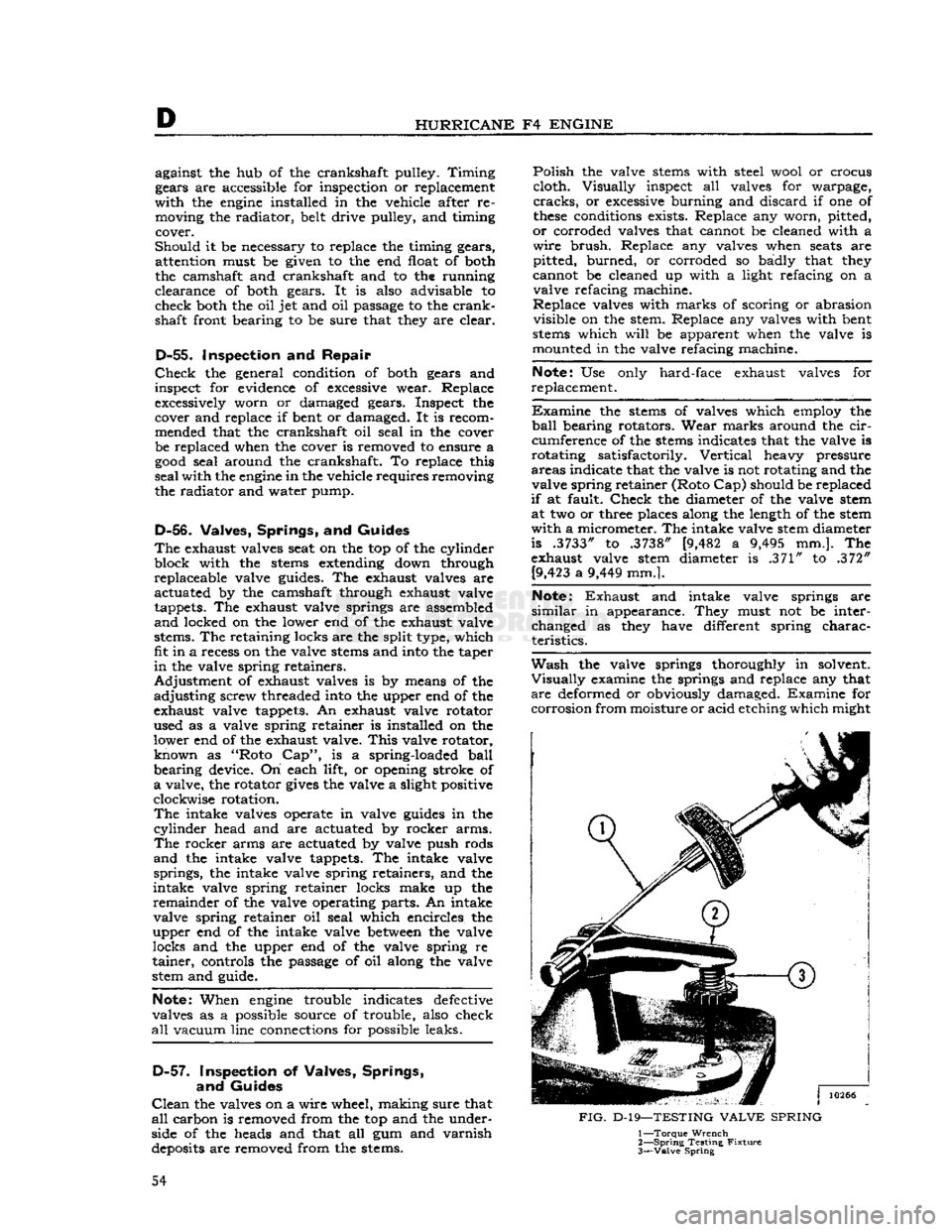
Wash
the valve springs thoroughly in solvent.
Visually
examine the springs and replace any that
are
deformed or obviously damaged. Examine for
corrosion
from moisture or acid etching which might
FIG.
D-19—TESTING
VALVE
SPRING
1—
Torque
Wrench
2—
Spring
Testing
Fixture
3—
Valve
Spring
54
Page 59 of 376

'Jeep*
UNIVERSAL SERIES SERVICE
MANUAL
D
10262
FIG.
D-26—FLOATING OIL INTAKE AND PAN 1—
Oil
Float
2—
Gasket
3—
Oil
Float Support
4—
Screw and Lockwasher 5—
Oil
Pan Gasket
6—
Oil
Pan 7—
Bolt
and Lockwasher
8—
Drain
Plug
9—
Drain
Plug Gasket
place it with the gasket in position. The rotors
should then rotate freely, providing that end float of the rotors is
less
than the thickness of the gasket
when compressed or .004" [0,102 mm.]. After as
sembling the gear on the pump shaft, check the
running
clearance
between
the gear and pump body with a feeler
gauge.
This
clearance should be
from
.022" to .051" [0,559 a 1,295 mm.].
Pump
output is controlled by a pressure relief valve.
CAUTION:
The oil pressure relief spring is
cali
brated.
Never stretch this spring to alter the relief valve pressure setting. Adjust this setting by the use of shims only. Shims are available that can be
added
between
the retainer and the spring to in
crease pressure. When shims are present, removing
shims
will
decrease pressure.
This
adjustment
will
change the pressure at higher
speeds
but not at idle speed. Safe minimum pres
sure
is 6 psi. [0,4 kg-cm2] at idle, at which point
the oil pressure light
goes
out; and 20 psi. [1,4
kg-cm2] at
2000
rpm. (32 mph. [51 kph.]).
D-66.
Oil Pan
Examine
the oil pan carefully for evidence of cor
rosion,
dents, or other damage. Special attention
should be given to the mounting flange to be sure of proper alignment and a tight seal at the cylinder
block, oil pan, and
engine
front plate. Whenever
the oil pan is removed, it is
best
to install a new
oil
pan gasket.
D-67.
Flywheel
The
flywheel is mounted on the
rear
flange of the
crankshaft.
The crankshaft, flywheel, and clutch
assembly are statically and dynamically balanced
separately and as a unit; therefore,
these
com
ponents
should be assembled in their original
rela
tive positions to maintain this balance.
D-68.
Flywheel Inspection
Clean
the flywheel thoroughly with cleaning sol vent. Inspect the clutch face of the flywheel for
a
burned or scuffed condition or rivet grooves.
Check
the flywheel for run-out or improper mount
ing according to the installation procedure given
in Par.
D-87.
If
the inner ends of the flywheel ring gear
teeth
are
only slightly burred cr snubbed, remove the burrs
and
reshape the
teeth
using a small emery wheel. 59
Page 76 of 376
Dl
DAUNTLESS
V-6
ENGINE
DM.
GENERAL
This
section describes service and repair of the
Dauntless V-6 engine. The
engine
code
number shown in
Fig.
A-4 is provided to identify the Daunt
less
V6-225 engine. The meaning of the coded letters and numbers that are stamped on the right front face of the crankcase, just below the rocker
arm
cover,
between
exhaust manifold ports, is given
below.
Letter
to
Designate
Market
M
—
Military
E
—
Export
D
— Domestic
Letter
to
Designate
Year
Built
N
— 1967
P
— 1968
R
— 1969
S
— 1970
T
— 1971
Letter
to Designate
Engine
and Compression
Ratio
H—V6-225
9.0 to 1
C.R.
(2 Bbl.
Carb.)
Y—V6-225
9.0 to 1
C.R.
Marine
(Low
Profile)
(2
Bbl.Carb.)
Z—V6-225
9.0 to 1
C.R.
Marine
(High
Profile)
(2 Bbl.
Carb.)
K—V6-225
7.6 to 1
C.R.
(2 Bbl.
Carb.)
L—V6-225
7.4 to 1
C.R.
(2 Bbl.
Carb.)
Market
Domestic
—
Year
"1967"
Engine
J
Day
Plus Chg. If
Any-
Service Engine "S"
Short
Block
"R" -Oversize Bores "B"
Undersize Crank
&
"A"
Rod
Bearings
The
identifying letter or letters follow the
engine
letters are decoded as follows:
A—.010"
Undersize
Main
and Connecting Rod
Bearings
B—.010"
Oversize Pistons
AB—Combination
of A and B
S—Service
Engine
R—Short
Block
All
disassembly and assembly procedures are pre sented in logical order, assuming a complete
engine
overhaul
with
engine
removed from the vehicle.
However,
many of
these
procedures can also be
performed as on-vehicle services if vehicle or
engine
components are removed to gain access to parts
involved.
Note:
Some
engines
are equipped with an exhaust
emission control system. Service information on
the components of this system is given in sec tion F2.
Dl-2.
ENGINE
DESCRIPTION
The
Dauntless V-6
engine
has a displacement of
225 cubic inches. It has a compression ratio of
9.0 to 1, which permits use of regular-grade
gaso
line.
See
Figs.
Dl-1 and Dl-2.
The
cylinder block is made of cast
iron.
Two banks
of cylinders (three cylinders per bank) are cast at a
90-degree
angle. The lower part of the cylinder-
block
extends
below the centerline of the
crank
shaft, forming a continuous flat surface with the
rear
crankshaft main bearing cap and the timing
chain
cover.
This
design allows installation of an
oil
pan with a
one-piece
gasket. The cylinders in
the left bank (as viewed from the driver's seat) are
numbered
1-3-5,
from front to
rear.
The cylinders
in
the right bank are numbered
2-4-6,
from front
to
rear.
The
crankshaft is supported in the cylinder block
by four steel-backed full-precision bearings, all of
which
have an identical diameter.
Crankshaft
main bearings are numbered 1 to 4, front to
rear.
The
thrust
bearing is flanged to maintain crankshaft position and to compensate against crankshaft end
thrust
The No. 2 bearing is the thrust bearing.
The
crankshaft is counterbalanced by weights,
which
are cast integral with the
crank
cheeks. The
weights
are shaped to a contour which
gives
mini
mum
clearance with cylinder barrels and piston
skirts
to conserve space.
Connecting
rods have I-beam sections with
bosses
on each side. Metal is removed, as required, to secure correct weight and balance. The lower end
of each connecting rod has a steel-backed preci
sion bearing. The piston pin is a press fit into the upper end. The outer ends of the piston pin
are
a slide fit in the piston
bosses.
The
full-skirted, aluminum alloy pistons are cam ground and tin plated. Two compression rings and
one oil control ring are installed above the piston
pin.
The cast iron compression rings in the two
upper
grooves
of the piston have a
groove
or bevel cut around the inner
edge
on one side. The
top compression ring is installed with this
groove
or
bevel up. The lower compression ring is installed
with
bevel down. The oil
ring,
in the lower groove,
consists of two thin steel
rails
separated by a
spacer.
It is backed by a hump-type spring-steel
expander.
V-6
engine
cylinder heads are made of cast
iron.
Their
valve
guides
are cast integrally. Right and left cylinder heads are identical and interchange
able. In service, however, it is
good
practice to
install
the cylinder heads on the side from which
they were removed.
The
valves are in line in each head, at an angle
10°
above the centerline of the cylinder bores.
Each
valve has a spring strong enough to ensure
positive valve seating throughout the operating speed range of the engine. The valve rocker arm
mechanism is protected by a
sheet
metal cover.
This
cover is seated on a raised surface of the
cylinder
head. It is gasketed to prevent oil leaks.
The
rocker arms for each bank of cylinders are mounted on a tubular steel shaft, supported on
the cylinder head by brackets. The rocker arms
are
made of aluminum. They have inserts at the
push
rod socket and the valve stem contact face.
The
camshaft is located above the crankshaft be
tween the two cylinder banks; it is supported in
four steel-backed babbitt-metal bearings. The cam shaft is driven at one-half crankshaft speed by
sprockets and a single outside-guide type chain.
Hydraulic
valve lifters and
one-piece
push rods operate overhead rocker arms and valves of both
banks
of cylinders from a single camshaft.
This
system requires no lash adjustment during assem
bly
or in service.
In
addition to its normal function of a cam follower,
each hydraulic valve lifter also serves as an auto- 76