2024 FORD F650/750 service schedule
[x] Cancel search: service schedulePage 239 of 386
3.Rotate the drain counterclockwise untilthe O-ring is visible. Allow the dieselfuel conditioner module to drain forapproximately 25 seconds or untilclean fuel is observed. Rotate the drainclockwise to tighten it. If no liquiddrains, there may be a clog in the drain.Have the conditioner module servicedby an authorized dealer.
4.Make sure that you fully tighten thedrain valve and then remove thecontainer from under your vehicle.
5.Restart the engine. If the Water in FuelDrain Filter message and lightcontinues to illuminate, have the fuelsystem checked and repaired.
ENGINE COOLANT CHECK -
6.7L DIESEL
WARNING: Do not remove thecoolant reservoir cap when the engine ison or the cooling system is hot. Wait 10minutes for the cooling system to cooldown. Cover the coolant reservoir capwith a thick cloth to prevent thepossibility of scalding and slowly removethe cap. Failure to follow this instructioncould result in personal injury.
WARNING: To reduce the risk ofpersonal injury, make sure the engine iscool before unscrewing the coolantpressure relief cap. The cooling systemis under pressure. Steam and hot liquidcan come out forcefully when you loosenthe cap slightly.
When the engine is cold, check theconcentration and level of the coolant atthe intervals listed in the scheduledmaintenance information. See ScheduledMaintenance (page 325).
Note:Make sure that the coolant level isbetween the MIN and the MAX marks onthe coolant reservoir.
Note: Coolant expands when it is hot. Thelevel may extend beyond the MAX mark.
Maintain coolant concentration within48% to 50%, which equates to a freezepoint between -30°F (-34°C) and -34°F(-37°C). Coolant concentration should bechecked using a refractometer. We do notrecommend the use of hydrometers orcoolant test strips for measuring coolantconcentration.
Adding Coolant
WARNING: Do not put coolant inthe windshield washer reservoir. Ifsprayed on the windshield, coolant couldmake it difficult to see through thewindshield.
WARNING: Do not add coolantfurther than the MAX mark.
WARNING: Do not add coolantwhen the vehicle is on or the coolingsystem is hot. Failure to follow thisinstruction could result in personal injury.
WARNING: Do not remove thecoolant reservoir cap when the engine ison or the cooling system is hot. Wait 10minutes for the cooling system to cooldown. Cover the coolant reservoir capwith a thick cloth to prevent thepossibility of scalding and slowly removethe cap. Failure to follow this instructioncould result in personal injury.
Note: Automotive fluids are notinterchangeable. Do not use coolant orwindshield washer fluid outside of itsspecified function and vehicle location.
235
2024 F-650/750 (TBC) , enUSA, Edition date: 202210, First-PrintingMaintenance
Page 247 of 386
At this time, you may notice the coolanttemperature gauge moves toward the redzone and a message may appear in theinformation display.
You may notice a reduction in vehiclespeed caused by reduced engine power inorder to manage the engine coolanttemperature. Your vehicle may enter thismode if certain high-temperature andhigh-load conditions take place. Theamount of speed reduction depends onvehicle loading, grade and ambienttemperature. If this occurs, there is noneed to pull off the road. You can continueto drive your vehicle.
The air conditioning may turn on and offduring severe operating conditions toprotect the engine from overheating. Whenthe coolant temperature decreases to thenormal operating temperature, the airconditioning turns on.
If the coolant temperature gauge movesfully into the red zone, or if the coolanttemperature warning or service enginesoon messages appear in your informationdisplay, do the following:
1.Pull off the road as soon as safelypossible and shift the transmission intopark (P).
2.Leave the engine running until thecoolant temperature gauge needlereturns to the normal position. Afterseveral minutes, if the temperaturedoes not drop, follow the remainingsteps.
3.Switch the engine off and wait for it tocool. Check the coolant level.
4.If the coolant level is at or below theminimum mark, add prediluted coolantimmediately.
5.If the coolant level is normal, restartthe engine and continue.
AUTOMATIC TRANSMISSION
FLUID CHECK
The transmission does not consume fluid.However, check the fluid level if thetransmission is not working properly, forexample if the transmission slips, shiftsslowly or if there are signs of fluid loss.
Replace the transmission fluid and filteron your vehicle at the specified serviceinterval. See Scheduled Maintenance(page 325).
Automatic transmission fluid expandswhen warmed. To check the fluid levelconsistently and accurately, do thefollowing:
1.Drive the vehicle until it reaches normaloperating temperature. This may takeup to 20 mi (30 km). Make sure thatthe transmission fluid temperaturegauge on the instrument cluster iswithin normal operating temperature196–215°F (91–102°C) beforechecking.
2.Make sure that your vehicle is on levelground.
3.With the engine running, parking brakeengaged and your foot on the brakepedal, move the gearshift lever throughall of the gear ranges. Allow sufficienttime for each gear to engage.
4.Make sure the parking brake is on. Makesure the transmission is in park (P) orneutral (N) and leave the enginerunning.
5.Open the hood. See Opening andClosing the Hood (page 223).
6.Remove the dipstick and wipe it witha clean, lint-free cloth. See UnderHood Overview (page 225).
7.Replace the dipstick and remove itagain to check the fluid level.
243
2024 F-650/750 (TBC) , enUSA, Edition date: 202210, First-PrintingMaintenance
Page 256 of 386
Regular fuel filter changes are animportant part of engine maintenance;failing to keep with the scheduledmaintenance could lead to engineperformance issues and fuel injectionsystem damage. See ScheduledMaintenance (page 325).
Use only recommended service partsconforming to specifications. SeeMotorcraft Parts (page 293).
Note:Using fuel that has high levels ofimpurities may require more frequent filterreplacements than the service intervalspecifies.
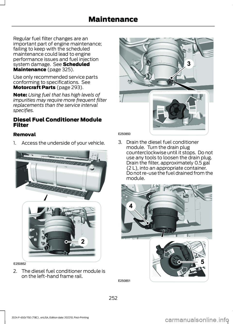
Diesel Fuel Conditioner ModuleFilter
Removal
1.Access the underside of your vehicle.
2.The diesel fuel conditioner module ison the left-hand frame rail.
3.Drain the diesel fuel conditionermodule. Turn the drain plugcounterclockwise until it stops. Do notuse any tools to loosen the drain plug.Drain the filter, approximately 0.5 gal(2 L), into an appropriate container.Do not re-use the fuel drained from themodule.
252
2024 F-650/750 (TBC) , enUSA, Edition date: 202210, First-PrintingMaintenanceE250852 E250850 E250851
Page 259 of 386
AIR INDUCTION SYSTEM
INSPECTION
WARNING: When performingmaintenance to any turbocharged enginewith engine air inlet piping disconnected,keep loose clothing, jewelry and long hairaway from the engine air inlet piping. Aturbocharger compressor air inletprotective shield should be installed overthe turbocharger air inlet to reduce therisk of personal injury or death.
Perform a complete inspection of the airinduction system annually.
In areas where road salt is used,disassemble the joints of each aluminumcomponent and inspect for salt build-upand presence of chlorine that can causealuminum particles to flake off and enterthe engine combustion chambers. Ifevidence of corrosion is found (usually atthe pipe connections), use a wire brush toclean the inside of the pipes and inside therubber hoses.
If pitting is evident at the joint ends of theintake pipes, use Motorcraft SiliconeGasket and Sealant TA-30 to seal thejoints. Make sure no excess material, whichcan pull into the engine, is on the inside ofthe pipes. If the service condition of thepipes, hoses or clamps is questionable,replace the defective part(s).
Make sure to clean all dust and debris outof the pipes and couplings with a clean,damp rag before reassembly.
Chassis-mounted Charge AirCooler
Visually inspect the core assembly fordebris and clogging of external fins withthe engine off.
Before engine operation, remove any debrisblocking the core.
•Turbocharger-to-charge air cooler.
•Charge air cooler-to-intake manifoldpipe.
•Mounting bracket.
•Chassis-mounted charge air coolercore.
Inspect air intake piping:
•Check for accumulation of saltdeposits (where applicable). If present,disassemble and clean the completeair intake piping system. If pitting isevident on the intake piping, useMotorcraft Silicone Gasket and SealantTA-30 to seal joints against leakage.
•Check for loose hoses and clamps.
•Check for ruptured or collapsed hoses.
•Check air cleaner housing for cracks.
EXHAUST SYSTEM
INSPECTION
Note:If your vehicle is equipped with acatalytic converter or muffler, do not blendwaste oil with diesel fuel. Operate only onultra-low sulfur (less than 15 parts permillion sulfur) diesel fuel with a cetanevalue of 45 or higher.
If your diesel engine is equipped with acatalytic converter, it is important to reviewthe maintenance schedule to make sureproper functioning of the catalyticconverter. Also, take precautions not todamage the catalytic converter whenservicing your engine or storing yourvehicle.
255
2024 F-650/750 (TBC) , enUSA, Edition date: 202210, First-PrintingMaintenance
Page 260 of 386
BRAKE SYSTEM INSPECTION
WARNING: Always wear arespirator approved by the NationalInstitute of Occupational Studies ofHealth (NIOSH) or Mine Safety andAppliance (MSA) during all brake serviceprocedures. Wear the respirator fromremoval of the wheels through assembly.Never use compressed air or dry brushingto clean brake parts or assemblies.Clean brake parts and assemblies inopen air. During assembly, carefullyplace all parts on the floor to avoidgetting dust in the air. Use an industrialvacuum cleaner with a HEPA filtersystem to clean dust from the brakedrums, backing plates and other brakeparts. After using the vacuum, removeany remaining dust with a rag soaked inwater and wrung until nearly dry.Never use compressed air or drysweeping to clean the work area. Use anindustrial vacuum cleaner with a HEPAfilter system and rags soaked in waterand wrung until nearly dry. Dispose ofused rags with care to avoid getting dustin the air. Use an approved respiratorwhen emptying vacuum cleaners andhandling used rags.Worker clean-up: Wash your handsbefore eating, drinking or smoking.Vacuum your work clothes after use andthen launder them separately, withoutshaking them, to prevent fiber dustgetting into the air.
Your vehicle is equipped withnon-asbestos brake linings. However,exposure to excessive amounts of brakematerial (whether asbestos ornon-asbestos, fiberglass, mineral wool,aramid or carbon) may be a serious healthhazard.
Air Brakes
WARNING: Do not manually adjustthe automatic slack adjusters to correctexcessive push rod stroke as it may resultin reduced brake effectiveness and avehicle crash. Excessive push rod strokeindicates that a problem exists with theautomatic adjuster, with the installationof the adjuster, or with foundation brakecomponents that manual adjustmentdoes not remedy. Seek service from aqualified facility for excessive push rodstroke.
Inspection and Adjustment
Establish a regular schedule for periodiccleaning, lubrication and adjustmentinspection based on vehicle use. Exactmaintenance intervals are difficult topredetermine due to vehicle applicationsand operating conditions. If you areuncertain of the proper schedule for yourvehicle, contact an authorized dealer.
Regular inspections should include:
•Periodic checking (every serviceinterval) of push rod travel or brakeadjustment. This is essential foreffective braking. Brake chamber pushrods on original equipment chambersnow incorporate an orange paintmarker near the base of the push rod
256
2024 F-650/750 (TBC) , enUSA, Edition date: 202210, First-PrintingMaintenance
Page 261 of 386
as a stroke indicator to aid inadjustment checks. If the push rod isclean and the brakes are out ofadjustment, you can see the orangemarker protruding from the chamberwhen the brakes are applied.
•Checking the brake lining (every serviceinterval). When brake linings or blockswear within 0.063 in (1.6 mm) theymust be replaced.
•Periodic checking (every serviceinterval) of the air compressor filter.Check the filter minder and when theindicator is near or on the red linemarked Service, replace the filter andreset the service filter minder.
Do not back off or disconnect the frontbrakes so that they are less effective,letting the rear brakes do all the stoppingof your vehicle. Do not overlook the brakeson the trailer either. Brake condition on thetrailer is just as important as the tractor.Proper brake balance on trucks andtractor-trailers is essential for effectivebraking.
Once a year, inspect the entire brakesystem:
•Rubber components for deterioration.A qualified technician should inspectthese components and replace themas necessary. Replacement intervalsvary according to the severity andlength of vehicle service.
•Condition of brake drums, brakechambers and slack adjusters.
•System for air leaks.
•Hose or pipes for rust, damage anddeterioration.
•Operation of service and parkingbrakes.
Periodically inspect parts such as air brakechamber diaphragm, air compressor andair cleaner. Replace any parts if you canconsider them unserviceable.
Air Dryer
Climactic conditions affect performanceof desiccant or after-cooler type air dryers.You must establish a maintenanceschedule for each specific operation.
The use of an air dryer on a vehicle doesnot eliminate the need to drain the airreservoirs periodically.
Inspect for moisture in the air system byopening reservoirs, draincocks or valvesand checking for presence of water. Thepresence of small amounts of water dueto condensation is normal and is not anindication that the dryer is not functioningproperly.
Replace or rebuild the desiccant cartridgewhen you determine that the desiccant iscontaminated and does not have adequatewater absorption capacity. The desiccantchange interval may vary. A generalrecommendation is to replace thedesiccant every 12 months (yearly). Ifexperience has shown that extended orshortened life has resulted for a particularinstallation, then the yearly interval can beincreased or decreased accordingly.
Draining the Air Brake Reservoir
WARNING: Failure to drain airbrake reservoirs can result in a reductionor loss of braking ability due to fluidaccumulation in the reservoir and/orpossible freeze-up during cold weather.
Completely drain all the air brake reservoirsdaily by opening the draincock at the endsof the tanks. (Where accessible.Pull-chains are used when the drains areundercab or otherwise inaccessible.) Closethe draincock after draining. Manually drain
257
2024 F-650/750 (TBC) , enUSA, Edition date: 202210, First-PrintingMaintenance
Page 262 of 386
any air tanks equipped with automaticmoisture ejector valves, as required, tomaintain a dry air system. Contact anauthorized dealer if you are unsure of theair reservoir locations or the drainingprocedure.
Hydraulic Brakes
Establish a regular schedule for periodiccleaning, lubrication and adjustmentinspection based on vehicle use. Exactmaintenance intervals are difficult topredetermine due to vehicle applicationsand operating conditions. If you areuncertain of the proper schedule for yourvehicle, contact an authorized dealer.
Regular inspections should include:
•Checking the brake lining (every serviceinterval). Establish inspection intervalsthat provide for lining replacementbefore damage to the disc occurs.Excessive lining wear may expose thebacking plate to the disc causingscoring of the disc faces. A qualifiedtechnician should perform this
inspection and keep to instructionsprovided by the service manual.Hydraulic brake systems arepower-assisted. There is a greatreduction in braking capabilitieswithout engine assist.
•Proper fluid level. The level should beat the bottom edge of the ring on eachreservoir fill port. Do not fill the mastercylinder to the top of the reservoir. Iffluid level requires attention tomaintain a proper master cylinder level,this is an indication of either severeoperation (pad wear) or fluid leakage.A more frequent and thorough brakeinspection is required.
•Brake lines, hoses and fittings. Repairor replace brake line tubes, hoses orfittings as required. Inspect thesecomponents every 4,000 mi(6,000 km) for the following.
•Lines for kinks, dents, corrosion orrupture.
•Hoses for abrasions, kinks, softspots or rupture, collapse, cracks,twists or loose frame supports.When replacing a hose, be surethere is adequate clearance to thehose to avoid an abrasion to thenew hose.
•All connections for leaks.
Driveline Parking Brake
WARNING: Use wheel chocks andexercise caution when inspecting underthe vehicle. A vehicle roll-away couldresult in property damage, personal injuryor death.
A qualified technician should adjust theparking brake and keep to the instructionsin the service manual.
258
2024 F-650/750 (TBC) , enUSA, Edition date: 202210, First-PrintingMaintenance
Page 263 of 386
AXLE INSPECTION
Front Axle
Maintaining the front axle alignment tospecifications is very important. A qualifiedtechnician should check and maintain thealignment.
Regular inspections should include:
•Toe-in inspection and adjustment (ifnecessary), particularly with radialtires.
•Checking for proper tightness of axlemounting U-bolt nuts, attaching ormounting bolts and nuts.
•Checking the axle for damage, binding,worn parts and adequate lubrication.
•Checking the kingpins for excessivewear. Also, perform this check duringother scheduled maintenance, forexample as tire rotation or service,wheel bearing service and alignment.See the workshop manual for properprocedures.
Toe-in
It is essential to maintain correct toe-inand tire pressure for optimum tire wear.
Inspecting steer axle tires in the first3,000–10,000 mi (5,000–16,000 km)generally shows if tires are wearingnormally.
Rapid outside shoulder wear on both tiresindicates too much toe-in.
Rapid inside shoulder wear on both tiresindicates too much toe-out.
In P&D-type service, there can be aleft-to-right steer tire tread life differentialup to 40% depending on routes and othervariables.
Follow the tire manufacturer'srecommended cold inflation pressure forthe tire size, load range (ply rating) andsteer axle loading typical for their operation(each steer axle tire equals ½ steer axleloading).
Special applications may warrant a settingbased on experience with the type of tireoperating loads and conditions. Radial tiresare more sensitive to toe-in setting thanbias ply tires. Fine tuning school busalignment to line-haul truck standardsdoes not drastically improve tire tread life.
STEERING SYSTEM
INSPECTION
WARNING: Failure to maintain thesteering system in proper condition cancause reduced steering ability resultingin property damage, personal injury ordeath.
Note:Have any steering problemsimmediately corrected by a qualified servicetechnician.
Ask your service technician to examine thesteering mechanism. Only minoradjustments may be necessary.
Regular inspections should include:
•Checking the tie rod, drag link endclamp bolts and ball joints for propertightness.
•Checking for installation and spread ofcotter pins and tightness of nuts atboth ends of the tie rod and drag link.
•Checking that the pitman arm (steeringarm at steering gear) mounting is tightand locked. Check system for leaks orhose chafing. Repair immediately, ifnecessary.
259
2024 F-650/750 (TBC) , enUSA, Edition date: 202210, First-PrintingMaintenance