2024 FORD F650/750 service indicator
[x] Cancel search: service indicatorPage 143 of 386
GENERAL INFORMATION
Note: Occasional brake noise is normal. Ifa metal-to-metal, continuous grinding orcontinuous squeal sound is present, thebrake linings may be worn-out. Have thesystem checked as soon as possible. If thevehicle has continuous vibration or shudderin the steering wheel while braking, have thesystem checked as soon as possible.
All standard equipment brakes areself-adjusting. Automatic adjustment,when required, occurs whenever you applyand release the brakes during forward orreverse operation.
Know the required stopping distances forall driving conditions you may encounter.For longer brake lining life, take fulladvantage of engine braking power whencoming to a stop.
Wet brakes result in reduced brakingefficiency. Gently press the brake pedal afew times when driving from a car wash orstanding water to dry the brakes.
If the brakes do not grip well:
•Check brake adjustment.
•Check the brake linings for excessivewear.
•Check the system air pressure onvehicles with air brakes.
•Let the brakes cool if you have beenusing them excessively, as in mountaindriving or after several fast, high-speedstops.
•If you have been driving through deepwater, gently apply the brakes severaltimes while your vehicle is movingslowly.
Brake Over Accelerator
In the event the accelerator pedalbecomes stuck or entrapped, apply steadyand firm pressure to the brake pedal toslow the vehicle and reduce engine power.If you experience this condition, apply thebrakes and bring your vehicle to a safestop. Move the transmission to park (P),switch the engine off and apply the parkingbrake. Inspect the accelerator pedal forany interference. If none are found and thecondition persists, have your vehicle towedto the nearest authorized dealer
Anti-lock Brake System
This system helps you maintain steeringcontrol during emergency stops by keepingthe brakes from locking.
If the light does not illuminateduring start up, remains on orflashes, the system may bedisabled. It also momentarily illuminateswhen you switch the ignition on to confirmthe lamp is functional. If it does notilluminate when you switch the ignition on,or begins to flash at any time, have thesystem checked.
If you connect a PLC trailer withthe ignition on, the trailer ABSlight also illuminates. If the lightfails to illuminate, if it remains on after youstart the vehicle or continues to flash, havethe system serviced immediately.
See Warning Lamps and Indicators(page 67).
139
2024 F-650/750 (TBC) , enUSA, Edition date: 202210, First-PrintingBrakesE67020 E210335
Page 148 of 386
Vehicles with Automatic Transmission
When you switch the ignition on, thesystem automatically turns on. You cannotturn the system on or off.
AIR BRAKES
WARNING: Failure to maintainproper air brake adjustment can resultin reduction or loss of braking ability.
WARNING: Do not drive or continueto drive if the low air pressure buzzer issounding or the brake warning light is lit.These warnings indicate that air pressureis not to normal operating level.Continued use of the vehicle could resultin loss of braking ability.
WARNING: Avoid repeated lightapplication of the brake pedal. Thisdepletes air pressure faster and couldresult in loss of braking capability.
WARNING: Do not move thevehicle when the air pressure isinsufficient because the brake systemmay be inoperative.
After starting the engine, allow time for theair compressor to build air pressure to60 psi (414 kPa) before moving yourvehicle.
Periodically check the air pressure gaugewhile driving. Pressure should rangebetween approximately 100 psi (690 kPa)to 130 psi (896 kPa). The air compressorgovernor cut-in and cutout pressuresettings are set at the factory and cannotbe adjusted.
When air pressure is insufficient(below 60 psi (414 kPa)), awarning light illuminates and abuzzer sounds when the ignition is on. Thismay happen because excessive brakeapplications are depleting the system airpressure. If this condition occurs, stopdriving your vehicle until the compressorhas fully recharged the air system.
Select a gear ratio to help slow your vehiclebefore descending grades. Supplementingwith brakes, as required, helps safely slowthe vehicle and avoids overspeeding theengine.
Air Chamber Stroke Indication -Drum Brakes
Air chamber push rods have orange strokeindicator markers that warn when thebraking system requires adjustment orrepair. The painted orange indicator is onthe air chamber push rod at the slackadjuster stroke dimension that requiresservice when visible during brakeapplication.
144
2024 F-650/750 (TBC) , enUSA, Edition date: 202210, First-PrintingBrakesE210336 E206772
Page 149 of 386

Only qualified service technicians shouldperform air brake inspection andadjustment or repairs.
Cam Brakes - Automatic SlackAdjusters - Drum Brakes
WARNING: Do not manually adjustthe automatic slack adjusters to correctexcessive push rod stroke as it may resultin reduced brake effectiveness and avehicle crash. Excessive push rod strokeindicates that a problem exists with theautomatic adjuster, with the installationof the adjuster, or with foundation brakecomponents that manual adjustmentdoes not remedy. Seek service from aqualified facility for excessive push rodstroke.
Standard air brakes (cam) are equippedwith automatic brake adjusters. Automaticadjustment occurs during brakeapplications. Inspect brakes for properadjustment at the specified intervals. SeeScheduled Maintenance (page 325).
Emergency Air Brake
WARNING: Do not continue tooperate the vehicle with a failure of oneof the brake systems. Take the vehicleto your dealer for service immediately.
Brake Wear Indicator - Disc Brakes
Inspect the brake wear indicator every timebefore starting the vehicle. The wearindicator length through the hole continuesto reduce depending on the brake padwear. Replace the brake pads immediatelyif the lining material thickness is 0.0787 in(2 mm) or less on either of the brake pads.
EXHAUST BRAKE (IF EQUIPPED)
WARNING: Do not use tow/haulwhen the road surface is slippery. Failureto follow this instruction could result inthe loss of control of your vehicle.
WARNING: Do not use dieselengine exhaust braking when the roadsurface is slippery. Failure to follow thisinstruction could result in the loss ofcontrol of your vehicle.
145
2024 F-650/750 (TBC) , enUSA, Edition date: 202210, First-PrintingBrakesE210337 E392040
Page 155 of 386
PRINCIPLE OF OPERATION
The traction control system helps avoiddrive wheel spin and loss of traction.
If your vehicle begins to slide, the systemapplies the brakes to individual wheelsand, when needed, reduces engine powerat the same time. If the wheels spin whenaccelerating on slippery or loose surfaces,the system reduces engine power in orderto increase traction.
USING TRACTION CONTROL -
VEHICLES WITH: AIR BRAKES
WARNING: Operating your vehiclewith the traction control disabled couldlead to an increased risk of loss of vehiclecontrol, vehicle rollover, personal injuryand death.
Press the TCS Off button on theinstrument panel to enable themud/snow mode.
This is beneficial when your vehicle is stuckin snow or on a slippery road surface. Thismode allows wheel spin to dig your vehicleout and allows you to rock your vehicle.
Press the switch again to select standardtraction control. The system automaticallyselects standard traction control at thenext ignition cycle.
System Indicator Light
Note:If the traction control light does notflash during a traction control event or staysilluminated, the system is not functioningproperly. Take your vehicle to an authorizeddealer for service.
During traction control operation, thetraction control light flashes rapidly andthe engine does not rev-up when you pressfurther on the accelerator. This is normaland is no reason for concern.
In mud/snow mode, the TCS OFF lightilluminates on the instrument cluster. If atraction event occurs in either mode, thestability and traction control light flashesrapidly.
USING TRACTION CONTROL -
VEHICLES WITH: HYDRAULIC
BRAKES
WARNING: Operating your vehiclewith the traction control disabled couldlead to an increased risk of loss of vehiclecontrol, vehicle rollover, personal injuryand death.
The system turns on each time you switchthe ignition on.
Use the traction control buttonon the instrument panel toswitch the system off or on.
If your vehicle is stuck in mud or snow,switching traction control off is beneficialas this allows the wheels to spin.
Press the button again to switch thetraction control system on.
System Indicator Light
Note:If the traction control light does notflash during a traction control event or stayson, the system is not operating. Have thesystem checked as soon as possible.
During a traction control event, the tractioncontrol light rapidly flashes. Pressingfurther on the accelerator does not causethe engine to rev higher. This is normal andis no reason for concern.
151
2024 F-650/750 (TBC) , enUSA, Edition date: 202210, First-PrintingTraction ControlE330660 E330660
Page 261 of 386
as a stroke indicator to aid inadjustment checks. If the push rod isclean and the brakes are out ofadjustment, you can see the orangemarker protruding from the chamberwhen the brakes are applied.
•Checking the brake lining (every serviceinterval). When brake linings or blockswear within 0.063 in (1.6 mm) theymust be replaced.
•Periodic checking (every serviceinterval) of the air compressor filter.Check the filter minder and when theindicator is near or on the red linemarked Service, replace the filter andreset the service filter minder.
Do not back off or disconnect the frontbrakes so that they are less effective,letting the rear brakes do all the stoppingof your vehicle. Do not overlook the brakeson the trailer either. Brake condition on thetrailer is just as important as the tractor.Proper brake balance on trucks andtractor-trailers is essential for effectivebraking.
Once a year, inspect the entire brakesystem:
•Rubber components for deterioration.A qualified technician should inspectthese components and replace themas necessary. Replacement intervalsvary according to the severity andlength of vehicle service.
•Condition of brake drums, brakechambers and slack adjusters.
•System for air leaks.
•Hose or pipes for rust, damage anddeterioration.
•Operation of service and parkingbrakes.
Periodically inspect parts such as air brakechamber diaphragm, air compressor andair cleaner. Replace any parts if you canconsider them unserviceable.
Air Dryer
Climactic conditions affect performanceof desiccant or after-cooler type air dryers.You must establish a maintenanceschedule for each specific operation.
The use of an air dryer on a vehicle doesnot eliminate the need to drain the airreservoirs periodically.
Inspect for moisture in the air system byopening reservoirs, draincocks or valvesand checking for presence of water. Thepresence of small amounts of water dueto condensation is normal and is not anindication that the dryer is not functioningproperly.
Replace or rebuild the desiccant cartridgewhen you determine that the desiccant iscontaminated and does not have adequatewater absorption capacity. The desiccantchange interval may vary. A generalrecommendation is to replace thedesiccant every 12 months (yearly). Ifexperience has shown that extended orshortened life has resulted for a particularinstallation, then the yearly interval can beincreased or decreased accordingly.
Draining the Air Brake Reservoir
WARNING: Failure to drain airbrake reservoirs can result in a reductionor loss of braking ability due to fluidaccumulation in the reservoir and/orpossible freeze-up during cold weather.
Completely drain all the air brake reservoirsdaily by opening the draincock at the endsof the tanks. (Where accessible.Pull-chains are used when the drains areundercab or otherwise inaccessible.) Closethe draincock after draining. Manually drain
257
2024 F-650/750 (TBC) , enUSA, Edition date: 202210, First-PrintingMaintenance
Page 338 of 386
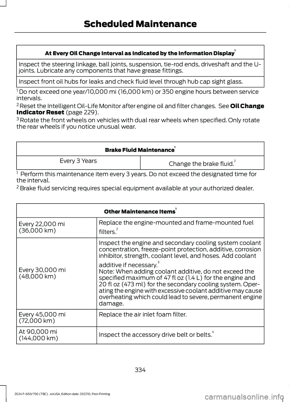
At Every Oil Change Interval as Indicated by the Information Display1
Inspect the steering linkage, ball joints, suspension, tie-rod ends, driveshaft and the U-joints. Lubricate any components that have grease fittings.
Inspect front oil hubs for leaks and check fluid level through hub cap sight glass.
1 Do not exceed one year/10,000 mi (16,000 km) or 350 engine hours between serviceintervals.2 Reset the Intelligent Oil-Life Monitor after engine oil and filter changes. See Oil ChangeIndicator Reset (page 229).3 Rotate the front wheels on vehicles with dual rear wheels when specified. Only rotatethe rear wheels if you notice unusual wear.
Brake Fluid Maintenance1
Change the brake fluid.2Every 3 Years
1 Perform this maintenance item every 3 years. Do not exceed the designated time forthe interval.2 Brake fluid servicing requires special equipment available at your authorized dealer.
Other Maintenance Items1
Replace the engine-mounted and frame-mounted fuel
filters.2Every 22,000 mi(36,000 km)
Inspect the engine and secondary cooling system coolantconcentration, freeze-point protection, additive, corrosioninhibitor, strength, coolant level, and hoses. Add coolant
additive if necessary.3
Every 30,000 mi(48,000 km)Note: When adding coolant additive, do not exceed thespecified maximum of 47 fl oz (1.4 L) for the engine and20 fl oz (473 ml) for the secondary cooling system. Oper-ating the engine with excessive coolant additive may causeoverheating which could lead to severe, permanent enginedamage.
Replace the air inlet foam filter.Every 45,000 mi(72,000 km)
Inspect the accessory drive belt or belts.4At 90,000 mi(144,000 km)
334
2024 F-650/750 (TBC) , enUSA, Edition date: 202210, First-PrintingScheduled Maintenance