2024 FORD F650/750 warning
[x] Cancel search: warningPage 199 of 386
This program is separate from the NewVehicle Limited Warranty, but the coverageis concurrent with the powertrain coverageperiod of your vehicle. Canadian roadsidecoverage and benefits may differ from theU.S. coverage. For complete details, seeyour Warranty Guide atwww.ford.com/support/warranty/.
Download the Sykes4Ford RoadsideAssistance App for access to your roadsideassistance services.
If you require more information, please callus in Canada at 1-800-665-2006, or visitour website at www.ford.ca.
Ford Motor Company reserves the right tomodify or discontinue Roadside Assistanceat any time. Certain restrictions apply toRoadside Assistance benefits.
For further details, call1-800-241-3673 (United States)1-800-665-2006 (Canada)
AUTOMATIC CRASH SHUTOFF
WHAT IS AUTOMATIC CRASHSHUTOFF
The automatic crash shutoff is designedto stop the fuel going to the engine in theevent of a moderate or severe crash.
Note:Not every impact causes a shutoff.
AUTOMATIC CRASH SHUTOFFPRECAUTIONS
WARNING: If your vehicle has beeninvolved in a crash, have the fuel systemchecked. Failure to follow this instructioncould result in fire, personal injury ordeath.
RE-ENABLING YOUR VEHICLE
1.Switch the ignition off.
2.Attempt to start your vehicle.
3.Switch the ignition off.
4.Attempt to start your vehicle.
Note:If your vehicle does not start after thethird attempt, have your vehicle checked assoon as possible.
195
2024 F-650/750 (TBC) , enUSA, Edition date: 202210, First-PrintingCrash and Breakdown Information
Page 206 of 386

FUSE SPECIFICATION CHART
Engine Compartment Fuse Box
WARNING: Always disconnect thebattery before servicing high currentfuses.
WARNING: To reduce risk ofelectrical shock, always replace thecover to the power distribution boxbefore reconnecting the battery orrefilling fluid reservoirs.
The engine compartment fuse box is in theengine compartment. It has high-currentfuses that protect your vehicle's mainelectrical systems from overloads.
If you disconnect and reconnect thebattery, you need to reset some features.See Changing the 12V Battery (page 246).
Replace fuses with the same type andrating. See Changing a Fuse (page 211).
Protected ComponentRatingItem
Horn.20 A1
Blower motor.40 A2
202
2024 F-650/750 (TBC) , enUSA, Edition date: 202210, First-PrintingFusesE251921
Page 214 of 386

Protected ComponentRatingItem
Right-hand front windowmotor.30 A26
Not used.—27
Not used.—28
Relay folding mirror.15 A29
Brake signal for air brake.5 A30Customer access stoplampsignal.Brake on-off isolation relay.Trailer tow stoplamp relay.
Upfitter interface module.10 A31Remote radio frequencyreceiver.
Radio.20 A32
Not used.—33
Not used.—34
Tow haul switch.5 A35
Lane departure warningcamera.15 A36
Mirror display.
Not used.—37
Left-hand front powerwindow switch (fourwindow units).
30 A38
Note:Spare fuse amperage may vary.
210
2024 F-650/750 (TBC) , enUSA, Edition date: 202210, First-PrintingFuses
Page 215 of 386
CHANGING A FUSE
Fuses
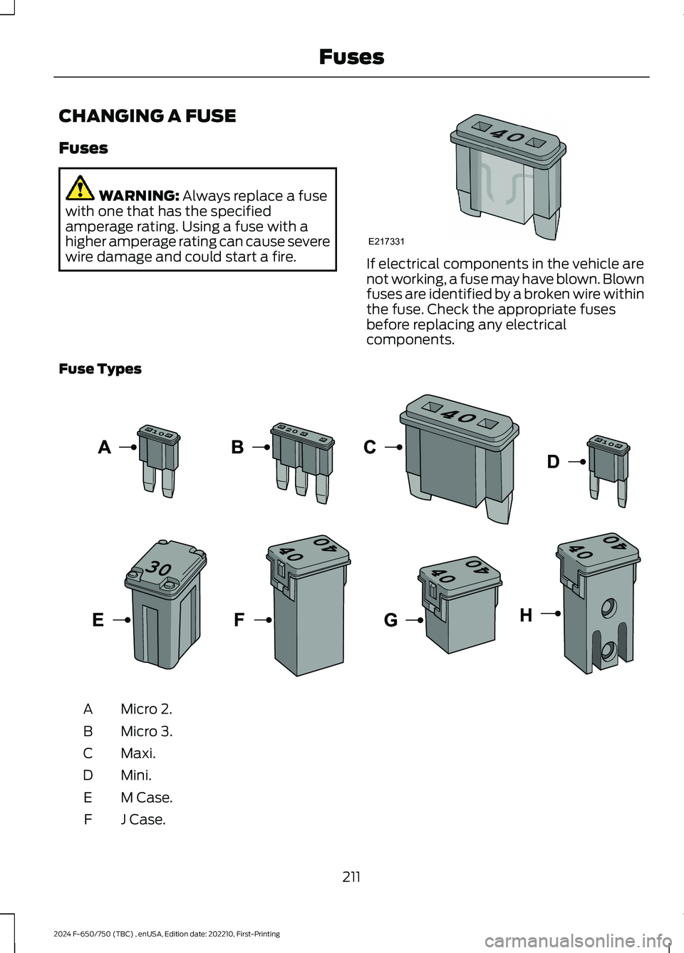
WARNING: Always replace a fusewith one that has the specifiedamperage rating. Using a fuse with ahigher amperage rating can cause severewire damage and could start a fire.If electrical components in the vehicle arenot working, a fuse may have blown. Blownfuses are identified by a broken wire withinthe fuse. Check the appropriate fusesbefore replacing any electricalcomponents.
Fuse Types
Micro 2.A
Micro 3.B
Maxi.C
Mini.D
M Case.E
J Case.F
211
2024 F-650/750 (TBC) , enUSA, Edition date: 202210, First-PrintingFusesE217331 E267379
Page 217 of 386
VEHICLE INSPECTION
INFORMATION
To make sure your vehicle is ready tooperate, conduct a pre-trip inspection atthe beginning of each work period. Followthe steps listed in this section to verify aproper vehicle inspection procedure.
WARNING: Exercise great cautionwhen working on a vehicle equipped withan automatic fan clutch. The fan startsin motion only after the engine coolantreaches a predetermined temperatureor the refrigerant pressure (if equippedwith air conditioning) reaches apredetermined setting. The fan starts atthis point with no advance warning.Never reach near, or permit objects toprotrude into, the fan blade radius whilethe engine is running as this could resultin vehicle damage, personal injury ordeath.
WARNING: Do not operate thevehicle if any suspension conditionslisted in the following charts are evident.Loss of steering or suspension couldresult in property damage, personal injuryor death.
WARNING: If a wheel must bechanged, obtain expert tire service help.Mounting and un-mounting of tiresshould only be performed by a qualifiedtechnician using necessary safetyprocedures and equipment, otherwisethe result could be property damage,personal injury or death.
Note:Always make sure you apply theparking brake before starting the engine.
Engine compartment (with engine off)
Use the dipstick to verify the oil level is in the proper operatingrange. See Engine Oil Dipstick (page 227).Engine oil
Look through the plastic reservoir and verify the coolant levelis within the proper operating range. Do not remove thepressure cap until the coolant has cooled. See EngineCoolant Check (page 238).
Engine coolant
Verify that the fluid level is in the proper operating range. SeePower Steering Fluid Check (page 246).Power steering fluid
Remove the master cylinder caps and inspect the fluid level.See Brake Fluid Check (page 245).Brake fluid
213
2024 F-650/750 (TBC) , enUSA, Edition date: 202210, First-PrintingVehicle Inspection Guide
Page 218 of 386
Engine compartment (with engine off)
Inspect for glazing, fraying or cracking. There should be nomore than 5-7 cracks per rib, per 1 in (2.5 cm)Belts (fan, alternator,water pump and airconditioningcompressor)
Inspect for signs of fluid puddles or dripping fluid on theground under the engine, or the underside of the engine.Fluid leaks
Inspect for debris that may have collected on the HVAC airinlet grille or inside the exterior module as this may reducesystem performance.
HVAC air inlet
Engine starting (with parking brake applied)
Before entering the cab, verify that the vehicle is equippedwith spare electrical fuses (if used), three red reflectivetriangles, a properly charged and rated fire extinguisher andwheel chocks.
Safety and emergencyequipment
Walk around the vehicle and verify all steps and grab handles,inside and out (as well as behind), are tight and clean. Useextreme caution and a three-point stance at all times.
Inspect door latches for proper closing, latching and locking.
Set the parking brake. Make sure the gearshift lever is inneutral (N) or park (P) (if equipped with a park position).Starting the engine
Diesel engine: Turn the key to the on position. Turn the keyto start when the wait to start indicator light in the instrumentcluster turns off.
Gasoline engine: Turn the key to start, and then release itas soon as the engine starts.
Verify pressure builds to normal operating range.Engine oil pressure
A tone indicating low air pressure should sound immediatelyafter the engine starts but before the compressor has built-up pressure. The tone should stop when the air pressurereaches 70 psi (483 kPa). Let the air pressure build togoverned cutout pressure, which should occur between115–130 psi (793–896 kPa).
Low air pressure warningtone (if equipped with anair compressor)
Press the accelerator and verify that it operates smoothly,without any binding or irregular feel. Release the pedal andverify the engine returns to idle speed immediately.
Accelerator
214
2024 F-650/750 (TBC) , enUSA, Edition date: 202210, First-PrintingVehicle Inspection Guide
Page 219 of 386
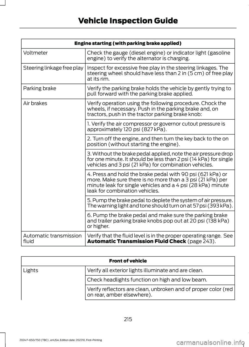
Engine starting (with parking brake applied)
Check the gauge (diesel engine) or indicator light (gasolineengine) to verify the alternator is charging.Voltmeter
Inspect for excessive free play in the steering linkages. Thesteering wheel should have less than 2 in (5 cm) of free playat its rim.
Steering linkage free play
Verify the parking brake holds the vehicle by gently trying topull forward with the parking brake applied.Parking brake
Verify operation using the following procedure. Chock thewheels, if necessary. Push in the parking brake and, ontractors, push in the tractor parking brake knob:
Air brakes
1. Verify the air compressor or governor cutout pressure isapproximately 120 psi (827 kPa).
2. Turn off the engine, and then turn the key back to the onposition (without starting the engine).
3. Without the brake pedal applied, note the air pressure dropfor one minute. It should be less than 2 psi (14 kPa) for singlevehicles and 3 psi (21 kPa) for combination vehicles.
4. Press and hold the brake pedal with 90 psi (621 kPa) ormore. Make sure there is no more than a 3 psi (21 kPa) perminute leak for single vehicles and a 4 psi (28 kPa) minuteleak for combination vehicles.
5. Pump the brake pedal to deplete the system of air pressure.The warning light and tone should turn on at 57 psi (393 kPa).
6. Pump the brake pedal and make sure the parking brakeand trailer parking brake knobs pop out at 20 psi (138 kPa)or higher.
Verify that the fluid level is in the proper operating range. SeeAutomatic Transmission Fluid Check (page 243).Automatic transmissionfluid
Front of vehicle
Verify all exterior lights illuminate and are clean.Lights
Check headlights function on high and low beam.
Verify reflectors are clean, unbroken and of proper color (redon rear, amber elsewhere).
215
2024 F-650/750 (TBC) , enUSA, Edition date: 202210, First-PrintingVehicle Inspection Guide
Page 224 of 386
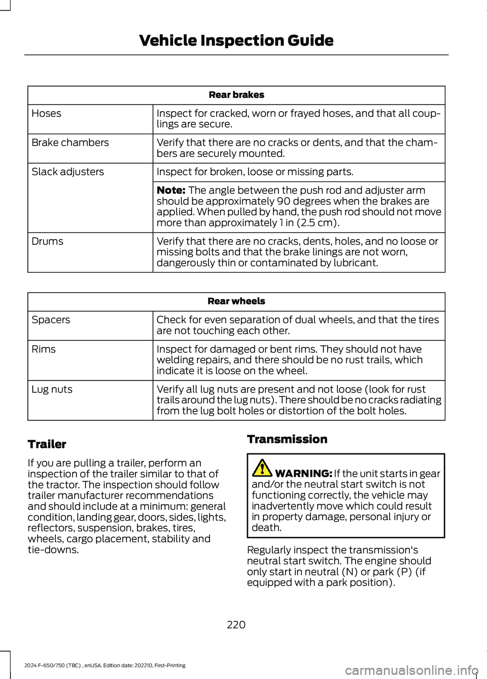
Rear brakes
Inspect for cracked, worn or frayed hoses, and that all coup-lings are secure.Hoses
Verify that there are no cracks or dents, and that the cham-bers are securely mounted.Brake chambers
Inspect for broken, loose or missing parts.Slack adjusters
Note: The angle between the push rod and adjuster armshould be approximately 90 degrees when the brakes areapplied. When pulled by hand, the push rod should not movemore than approximately 1 in (2.5 cm).
Verify that there are no cracks, dents, holes, and no loose ormissing bolts and that the brake linings are not worn,dangerously thin or contaminated by lubricant.
Drums
Rear wheels
Check for even separation of dual wheels, and that the tiresare not touching each other.Spacers
Inspect for damaged or bent rims. They should not havewelding repairs, and there should be no rust trails, whichindicate it is loose on the wheel.
Rims
Verify all lug nuts are present and not loose (look for rusttrails around the lug nuts). There should be no cracks radiatingfrom the lug bolt holes or distortion of the bolt holes.
Lug nuts
Trailer
If you are pulling a trailer, perform aninspection of the trailer similar to that ofthe tractor. The inspection should followtrailer manufacturer recommendationsand should include at a minimum: generalcondition, landing gear, doors, sides, lights,reflectors, suspension, brakes, tires,wheels, cargo placement, stability andtie-downs.
Transmission
WARNING: If the unit starts in gearand/or the neutral start switch is notfunctioning correctly, the vehicle mayinadvertently move which could resultin property damage, personal injury ordeath.
Regularly inspect the transmission'sneutral start switch. The engine shouldonly start in neutral (N) or park (P) (ifequipped with a park position).
220
2024 F-650/750 (TBC) , enUSA, Edition date: 202210, First-PrintingVehicle Inspection Guide