2023 TOYOTA YARIS CROSS airbag off
[x] Cancel search: airbag offPage 57 of 698
55
1
Owners Manual_Europe_M52N75_en
1-2. Child safety
For safety and security
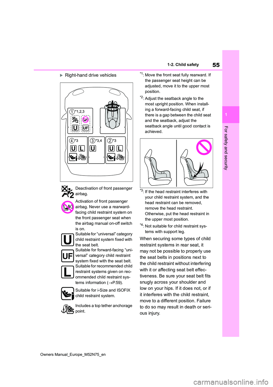
Right-hand drive vehicles*1: Move the front seat fully rearward. If
the passenger seat height can be
adjusted, move it to the upper most
position.
*2: Adjust the seatback angle to the
most upright position. When install-
ing a forward-facing child seat, if
there is a gap between the child seat
and the seatback, adjust the
seatback angle until good contact is
achieved.
*3: If the head restraint interferes with
your child restraint system, and the
head restraint can be removed,
remove the head restraint.
Otherwise, put the head restraint in
the upper most position.
*4: Not suitable for child restraint sys-
tems with support leg.
When securing some types of child
restraint systems in rear seat, it
may not be possible to properly use
the seat belts in positions next to
the child restraint without interfering
with it or affecting seat belt effec-
tiveness. Be sure your seat belt fits
snugly across your shoulder and
low on your hips. If it does not, or if
it interferes with the child restraint,
move to a different position. Failure
to do so may result in death or seri-
ous injury.
Deactivation of front passenger
airbag.
Activation of front passenger
airbag. Never use a rearward-
facing child restraint system on
the front passenger seat when
the airbag manual on-off switch
is on.
Suitable for “universal” category
child restraint system fixed with
the seat belt.
Suitable for forward-facing “uni-
versal” category child restraint
system fixed with the seat belt.
Suitable for recommended child
restraint systems given on rec-
ommended child restraint sys-
tems information ( P. 5 9 ) .
Suitable for i-Size and ISOFIX
child restraint system.
Includes a top tether anchorage
point.
Page 58 of 698
56
Owners Manual_Europe_M52N75_en
1-2. Child safety
When installing a child restraint
in the rear seats, adjust the front
seat so that it does not interfere
with the child or child restraint
system.
When installing a child seat with
support base, if the child seat
interferes with the seatback
when latching it into the support
base, adjust the seatback rear-
ward until there is no interfer-
ence.
If the seat belt shoulder anchor is
ahead of the child seat belt
guide, move the seat cushion
forward.
When installing a junior seat, if
the child in your child restraint
system is in a very upright posi-
tion, adjust the seatback angle to
the most comfortable position.
And if the seat belt shoulder
anchor is ahead of the child seat
belt guide, move the seat cush-
ion forward.
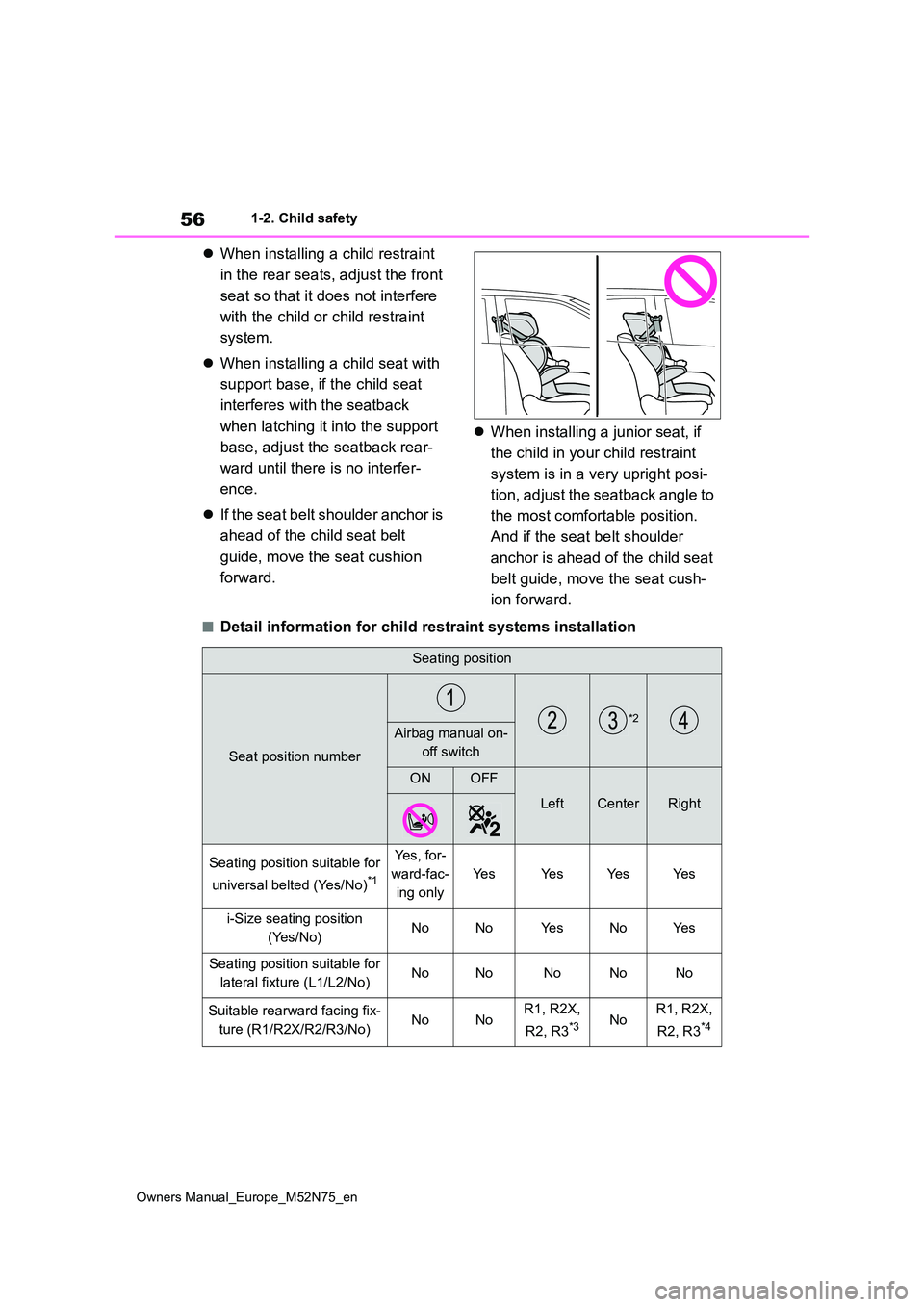
■Detail information for child r estraint systems installation
Seating position
Seat position number
*2Airbag manual on-
off switch
ONOFF
LeftCenterRight
Seating position suitable for
universal belted (Yes/No)*1
Ye s , f o r -
ward-fac-
ing only
Ye sYe sYe sYe s
i-Size seating position
(Yes/No)NoNoYe sNoYe s
Seating position suitable for
lateral fixture (L1/L2/No)NoNoNoNoNo
Suitable rearward facing fix-
ture (R1/R2X/R2/R3/No)NoNoR1, R2X,
R2, R3*3NoR1, R2X,
R2, R3*4
Page 59 of 698

57
1
Owners Manual_Europe_M52N75_en
1-2. Child safety
For safety and security
*1: All universal categories (group 0, 0+, I, II and III).
*2: Not suitable for child restraint systems with support leg.
*3: Adjust the driver’s seat to the highest position.
*4: Before installing a child restraint system to this seat, adjust the position of the
front passenger’s seat to between the 1st lock position and 12t h lock position
(16th lock position from the rear).
1st lock position
12th lock position
Toyota suggests the users to use and seating positions.
ISOFIX child restraint systems are divided into different “fixt ure”. The child
restraint system can be used in the seating positions for “fixt ure” mentioned
in the table above. For kind of “ fixture” relation, confirm the following table.
If your child restraint system ha s no kind of “fixture” (or if you cannot find
information in the table below), please refer to the child rest raint system
Suitable forward facing fix-
ture (F2X/F2/F3/No)NoNoF2X, F2,
F3NoF2X, F2,
F3
Suitable junior seat fixture
(B2/B3/No)NoNoB2, B3NoB2, B3
Seating position
Seat position number
*2Airbag manual on-
off switch
ONOFF
LeftCenterRight
Page 331 of 698

329
4
Owners Manual_Europe_M52N75_en
4-5. Using the driving support systems
Driving
prevent the drive wheels from spin-
ning when starting the vehicle or
accelerating on slippery roads
■Active Cornering Assist (ACA)
Helps to prevent the vehicle from
drifting to the outer side by perform-
ing inner wheel brake control when
attempting to accelerate while turn-
ing
■Hill-start assist control
Helps to reduce the backward
movement of the vehicle when
starting on an uphill
■EPS (Electric Power Steering)
Employs an electric motor to
reduce the amount of effort needed
to turn the steering wheel.
■E-Four (Electronic On-Demand
AWD system) (AWD models)
Automatically switches from front
wheel drive to all-wheel drive
(AWD) according to the driving con-
ditions, helping to ensure reliable
handling and stability. Examples of
conditions where the system will
switch to AWD are when cornering,
going uphill, starting off or acceler-
ating, and when the road surface is
slippery due to snow, rain, etc.
■Emergency brake signal
When the brakes are applied sud-
denly, the emergency flashers auto-
matically flash to alert the vehicle
behind.
■The Secondary Collision
Brake
When the SRS airbag sensor
detects a collision and the system
operates, the brakes and brake
lights are automatically controlled
to reduce the vehicle speed and
help reduce the possibility of further
damage due to a secondary colli-
sion.
■When the TRC/VSC/ABS systems are operating
The slip indicator light will flash while the
TRC/VSC/ABS systems are operating.
■Disabling the TRC system
If the vehicle gets stuck in mud, dirt or
snow, the TRC system may reduce
power from the hybrid system to the
wheels. Pressing to turn the system
off may make it easier for you to rock the
vehicle in order to free it.
To turn the TRC system off, quickly
press and release .
The “Traction Control Turned OFF” will
be shown on the multi-information dis-
play.
Press again to turn the system
back on.
Page 353 of 698
351
5
Owners Manual_Europe_M52N75_en
5-2. Using the interior lights
Interior features
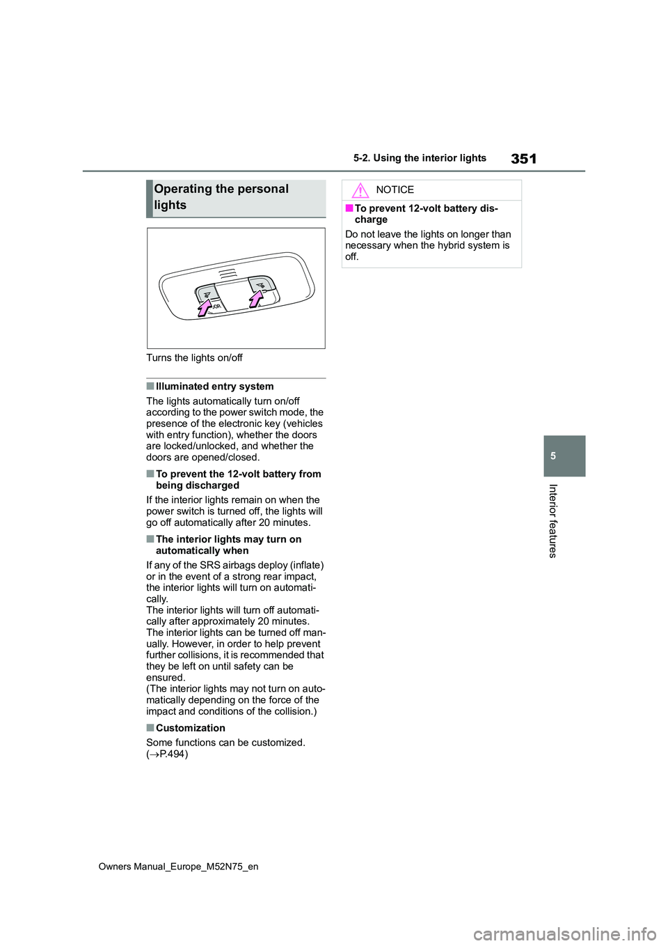
Turns the lights on/off
■Illuminated entry system
The lights automatically turn on/off according to the power switch mode, the presence of the electronic key (vehicles
with entry function), whether the doors are locked/unlocked, and whether the doors are opened/closed.
■To prevent the 12-volt battery from
being discharged
If the interior lights remain on when the power switch is turned off, the lights will
go off automatically after 20 minutes.
■The interior lights may turn on automatically when
If any of the SRS airbags deploy (inflate)
or in the event of a strong rear impact, the interior lights will turn on automati-cally.
The interior lights will turn off automati- cally after approximately 20 minutes.The interior lights can be turned off man-
ually. However, in order to help prevent further collisions, it is recommended that they be left on until safety can be
ensured. (The interior lights may not turn on auto-matically depending on the force of the
impact and conditions of the collision.)
■Customization
Some functions can be customized. ( P.494)
Operating the personal
lights
NOTICE
■To prevent 12-volt battery dis- charge
Do not leave the lights on longer than necessary when the hybrid system is off.
Page 374 of 698
372
Owners Manual_Europe_M52N75_en
6-1. Maintenance and care
WARNING
■Water in the vehicle
●Do not splash or spill liquid in the
vehicle, such as on the floor, in the hybrid battery (traction battery) air intake vent, and in the luggage
compartment. ( P.371) Doing so may cause the hybrid bat-tery, electrical components, etc. to
malfunction or catch fire.
●Do not get any of the SRS compo-
nents or wiring in the vehicle interior wet. ( P. 3 8 ) An electrical malfunction may
cause the airbags to deploy or not function properly, resulting in death or serious injury.
●Vehicles with wireless charger:Do not let the wireless charger
( P.359) get wet. Failure to do so may cause the charger to become hot and cause burns or could cause
electric shock resulting in death or serious injury.
■Cleaning the interior (especially instrument panel)
Do not use a polish wax or polish
cleaner. The instrument panel may reflect off the windshield, obstructing the driver’s view and leading to an
accident, resulting in death or serious injury.
NOTICE
■Cleaning detergents
●Do not use the following types of
detergent, as they may discolor the vehicle interior or cause streaks or damage to painted surfaces:
• Non-seat portions: Organic sub- stances such as benzene or gaso-
line, alkaline or acidic solutions, dye, and bleach
• Seats: Alkaline or acidic solutions, such as thinner, benzene, and alco-hol
●Do not use a polish wax or polish cleaner. The instrument panel’s or
other interior part’s painted surface may be damaged.
■Preventing damage to leather surfaces
Observe the following precautions to
avoid damage to and deterioration of leather surfaces:
●Remove any dust or dirt from
leather surfaces immediately.
●Do not expose the vehicle to direct
sunlight for extended periods of time. Park the vehicle in the shade, especially during summer.
●Do not place items made of vinyl, plastic, or containing wax on the
upholstery, as they may stick to the leather surface if the vehicle interior heats up significantly.
■Water on the floor
Do not wash the vehicle floor with
water. Vehicle systems such as the audio system may be damaged if water
comes into contact with electrical components such as the audio sys-tem above or under the floor of the
vehicle. Water may also cause the body to rust.
■When cleaning the inside of the windshield (vehicles with Toyota Safety Sense)
Do not allow glass cleaner to contact the lens. Also, do not touch the lens. ( P.226)
Page 428 of 698

426
Owners Manual_Europe_M52N75_en
7-1. Essential information
7-1.Esse ntial informa tion
Press the switch.
All the turn signal lights will flash.
To turn them off, press the switch once
again.
■Emergency flashers
●If the emergency flashers are used for a long time while the hybrid system is
not operating (while the “READY” indi- cator is not illuminated), the 12-volt battery may discharge.
●If any of the SRS airbags deploy (inflate) or in the event of a strong rear
impact, the emergency flashers will turn on automatically. The emergency flashers will turn off
automatically after operating for approximately 20 minutes. To manu-ally turn the emergency flashers off,
press the switch twice. (The emergency flashers may not turn on automatically depending on the
force of the impact and conditions of the collision.)
1 Steadily step on the brake pedal
with both feet and firmly depress
it.
Do not pump the brake pedal repeat- edly as this will increase the effort required to slow the vehicle.
2 Shift the shift lever to N.
If the shift lever is shifted to N
3 After slowing down, stop the
vehicle in a safe place by the
road.
4 Stop the hybrid system.
If the shift lever cannot be shifted
to N
3 Keep depressing the brake
pedal with both feet to reduce
vehicle speed as much as possi-
ble.
4 Perform the following proce-
dure to stop the hybrid system:
Vehicles without a smart entry &
start system
Turn the power switch to ACC.
Emergency flashers
The emergency flashers are
used to warn other drivers
when the vehicle has to be
stopped on the road due to a
breakdown, etc.
Operating instructions
If your vehicle has to be
stopped in an emer-
gency
Only in an emergency, such as
if it becomes impossible to
stop the vehicle in the normal
way, stop the vehicle using the
following procedure:
Stopping the vehicle
Page 460 of 698
458
Owners Manual_Europe_M52N75_en
7-2. Steps to take in an emergency
WARNING
●Keep back from the tire while it is
being repaired, as there is a chance
of it bursting while the repair opera-
tion is being performed. If you
notice any cracks or deformation of
the tire, turn (off) the compres-
sor switch and stop the repair oper-
ation immediately.
●The repair kit may overheat if oper- ated for a long period of time. Do
not operate the repair kit continu- ously for more than 40 minutes.
●Parts of the repair kit become hot during operation. Be careful when handling the repair kit during and
after operation. Do not touch the metal part around the connecting area between the bottle and com-
pressor. It will be extremely hot.
●Do not attach the vehicle speed
warning sticker to an area other than the one indicated. If the sticker is attached to an area where an
SRS airbag is located, such as the pad of the steering wheel, it may prevent the SRS airbag from oper-
ating properly.
●To avoid risk of burst or severe
leakage, do not drop or damage the bottle. Visually inspect the bottle before use. Do not use a bottle with
shock, crack, scratch, leakage or any other damage. In such case, immediately replace.
■Driving to spread the liquid seal-
ant evenly
Observe the following precautions to reduce the risk of accidents.
Failing to do so may result in a loss of vehicle control and cause death or serious injury.
●Drive the vehicle carefully at a low speed. Be especially careful when
turning and cornering.
●If the vehicle does not drive straight or you feel a pull through the steer-ing wheel, stop the vehicle and
check the following.
• Tire condition. The tire may have
separated from the wheel.
• Tire inflation pressure. If the tire
inflation pressure is 130 kPa (1.3
kgf/cm2 or bar, 19 psi) or less, the tire may be severely damaged.
NOTICE
■When performing an emergency repair
●A tire should only be repaired with
the emergency tire puncture repair kit if the damage is caused by a sharp object such as nail or screw
passing through the tire tread. Do not remove the sharp object from the tire. Removing the object
may widen the opening and disena- ble emergency repair with the repair kit.
●The repair kit is not waterproof. Make sure that the repair kit is not
exposed to water, such as when it is being used in the rain.
●Do not put the repair kit directly onto dusty ground such as sand at the side of the road. If the repair kit
vacuums up dust etc., a malfunc- tion may occur.
●Do not turn the bottle upside down when using it, as doing so may cause damage to the compressor.
■Precautions for the emergency tire puncture repair kit
●The repair kit power source should be 12 V DC suitable for vehicle use. Do not connect the repair kit to any
other source.