2023 TOYOTA SUPRA display
[x] Cancel search: displayPage 241 of 372

2413-1. CONTROLS
3
CONTROLS
6Set the departure time.
7 Select day of the week, if
needed.
■Functional requirement
If a departure time is to influ-
ence the switching on of
parked-car ventilation, the
respective departure time must
be activated first.
■Via Toyota Supra Command
1 "My Vehicle"
2 "Vehicle settings"
3 "Climate functions"
4 "Comfort ventilation"
5 "For departure time"
6 Activate the desired depar-
ture time.
The symbol on the automatic
air conditioning signals an acti-
vated departure time. This chapter describes all stan-
dard, country-specific and
optional features offered with
the series. It also describes fea-
tures and functions that are not
necessarily available in your
vehicle, e.g., due to the selected
options or country versions. This
also applies to safety-related
functions and systems. When
using these functions and sys-
tems, the applicable laws and
regulations must be observed.
The integrated Universal
Remote Control in the interior
mirror can operate up to 3 func-
tions of remote-controlled sys-
tems such as garage door
drives, barriers, or lighting sys-
tems.
The Integrated Universal
Remote Control replaces up to 3
different hand-held transmitters.
To operate the remote control,
the buttons on the interior mirror
must be programmed with the
Activating the departure time
Display
Interior equipment
Vehicle features and
options
Integrated Universal
Remote Control
Concept
General information
Page 247 of 372

2473-1. CONTROLS
3
CONTROLS
devices.
Charging current:
max. 1.5 A (vehicles without wire-
less charger)
max. 2.1 A (vehicles with wireless
charger)
For data transfer.
The wireless charging tray
allows wireless charging of
mobile phones and other mobile
devices certified according to
the Qi standard.
When inserting the device to be
charged, ensure that there are
no objects between the device
to be charged and the wireless
charging tray. The charging process is
shown by the charge indicator
on the control display.
This device has been tested for
human exposure limits and found
compliant at a minimum distance of
4 in/10 cm during operation.
Therefore, a dist ance of 4 in/10 cm
must be maintained in every direc-
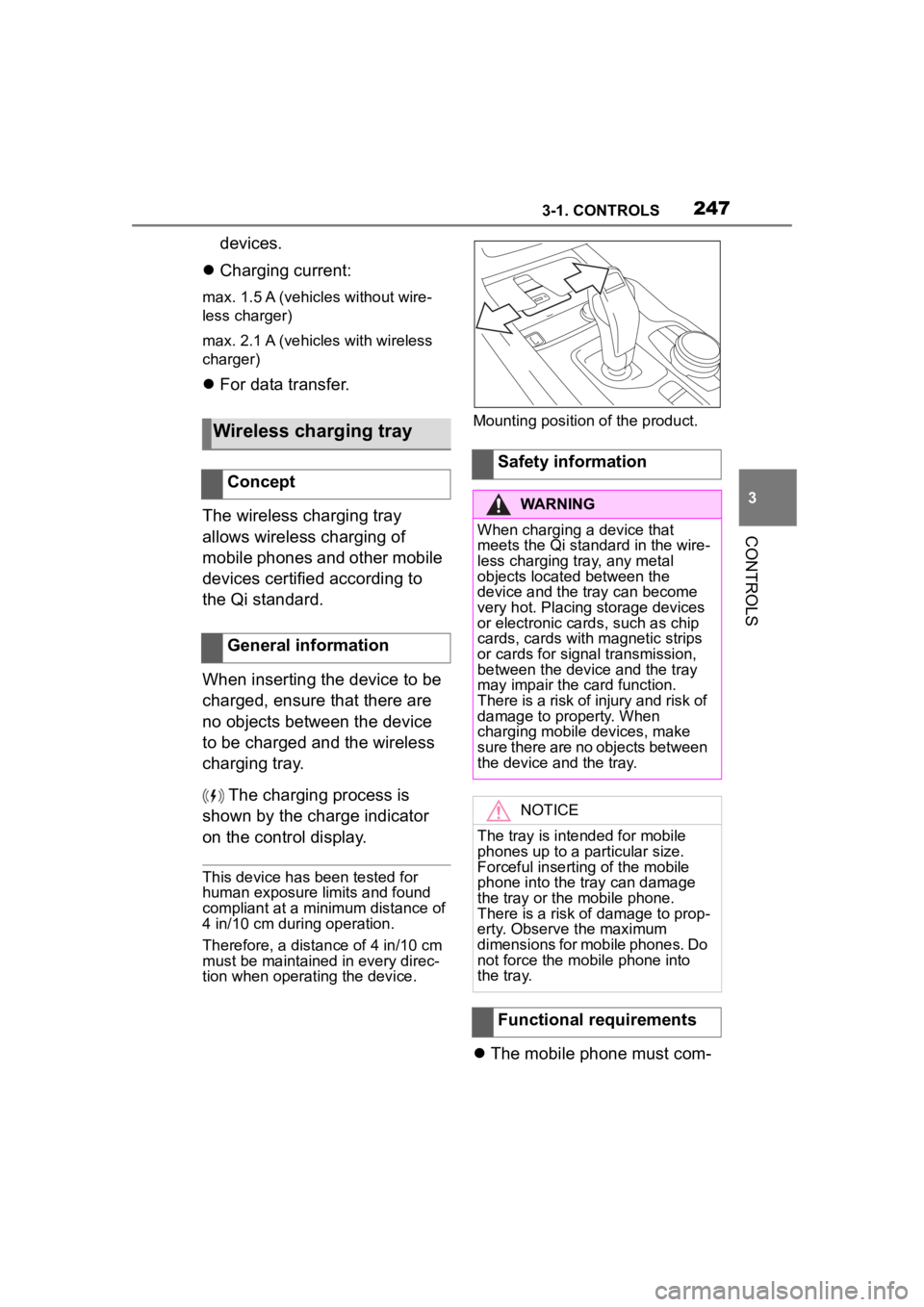
tion when operating the device. Mounting position of the product.
The mobile phone must com-
Wireless charging tray
Concept
General information
Safety information
WARNING
When charging a device that
meets the Qi standard in the wire-
less charging tray, any metal
objects located between the
device and the tray can become
very hot. Placing storage devices
or electronic card s, such as chip
cards, cards with magnetic strips
or cards for signal transmission,
between the device and the tray
may impair the card function.
There is a risk of injury and risk of
damage to property. When
charging mobile devices, make
sure there are no objects between
the device and the tray.
NOTICE
The tray is intended for mobile
phones up to a particular size.
Forceful inserting of the mobile
phone into the tray can damage
the tray or the mobile phone.
There is a risk of damage to prop-
erty. Observe the maximum
dimensions for mobile phones. Do
not force the mobile phone into
the tray.
Functional requirements
Page 248 of 372

2483-1. CONTROLS
patibly support the required Qi
standard.
Standby state is switched on.
Observe the maximum
dimensions of the mobile
phone.
Use only protective jackets
and covers up to a maximum
thickness of 0.07 in/2 mm.
Otherwise, the charging func-
tion may be impaired.
The mobile phone to be
charged is located in the cen-
ter of the tray.
1 LED
2 Storage area
Place the mobile phone cen-
tered in the storage tray with the
display facing up.
The mobile phone must not exceed
the maximum size of approximately
6.0 x 3.1 x 0.7 in /154.5 x 80 x 18 mm.
If the vehicle is equipped with
the forgotten warning function, a
warning can be output if a
mobile phone with Qi capability
was forgotten in the wireless
charging tray when leaving the
vehicle.
The forgotten warning is dis-
played in the instrument cluster.
Operation
Overview
Inserting the mobile phone
LED displays
ColorMeaning
Blue
The mobile phone is
charging.
Depending on the model
and the vehicle, the blue
LED is no longer illumi-
nated once the inserted
mobile phone with Qi
capability is fully charged.
Orange
The mobile phone is not
charging.
Temperature on the
mobile phone possibly
too high or foreign object
in the charging tray.
Red
The mobile phone is not
charging.
Contact your Toyota
dealer.
Forgotten warning
General information
Page 249 of 372

2493-1. CONTROLS
3
CONTROLS
Via Toyota Supra Command:
1“My Vehicle”
2 “System settings”
3 “Wireless charging tray”
4 “Forgotten mobile device
alert”
The charge current may be
reduced or the charging process
may be temporarily interrupted
in the following situations:
Due to excessive tempera-
tures on the surface of the
tray and mobile phone.
If there are objects between
the mobile phone and the
wireless charging tray.
By settings on the mobile
phone, for instance for
charging. Follow the relevant
instructions control display
and in the instructions for the
mobile phone, if applicable.
Your car is equipped with a wire-
less charging tray (WCA) to
charge your mobile phone and
connect it to the mobile network.
To ensure the best possible con-
nection a signal booster
(LTE-Compensator) is used in
conjunction with the WCA. The following paragraphs refer to
this booster:
This is a CONSUMER device.
BEFORE USE, you MUST
REGISTER THIS DEVICE with
your wireless provider and have
your provider's consent. Most
wireless providers consent to
the use of Compensators. Some
providers may not consent to
the use of this device on their
network. If you are unsure, con-
tact your provider. You MUST
operate this device with
approved antennas and cables
as specified by the manufac-
turer. Antennas MUST be
installed at least 20 cm (8
inches) from any person. You
MUST cease operating this
device immediately if requested
by the FCC or a licensed wire-
less service provider. Warning
E911 location information may
not be provided or may be inac-
curate for calls served by using
this device.
Please observe additionally the
following information
Sprint Nextel will allow con-
sumers to register their signal
boosters by calling their
toll-free number.
T-Mobile online registration
link:
(www.T-Mobile.com/Booster-
Registration);
(https://saqat.t-mobile.com/sit
es/SignalBooster#).
Activating
System limits
LTE-Compensator - Infor-
mation and User Manual
Page 271 of 372

2715-1. MOBILITY
5
MOBILITY
The current tire inflation pres-
sure values and the intended
tire inflation pressure values for
the mounted tires can be dis-
played on the Control Display.
To ensure that they are dis-
played correctly, the tire sizes
must be stored in the system
and must have been set, refer to
page 287, for the mounted tires.
The current tire inflation pres-
sure value is located on each
tire.
The reference tire inflation pres-
sure value is located in the
lower area of the Control Dis-
play.
Tires heat up while driving. The
tire inflation pressure increases
with the tire temperature.
Tires have a natural, consistent
loss of tire inflation pressure.
The displays of inflation devices
may under-read by up to 0.1
bar/2 psi.The tire inflation pressure speci-
fications in the tire inflation pres-
sure table only relate to cold
tires or tires at the same tem-
perature as the ambient tem-
perature.
Only check the tire inflation
pressure levels when the tires
are cold, i.e.:
• Driving range of max. 1.25
miles/2 km has not been
exceeded.
• If the vehicle has not moved again for at least 2 hours after
a trip.
Check the tire inflation pressure
of the emergency wheel in the
cargo area regularly, and correct
it as needed.
1 Determine, refer to page 270,
the intended tire inflation
pressure levels for the
mounted tires.
2 Check the tire inflation pres-
sure in all four tires, using a
pressure gauge, for example.
3 Correct the tire inflation pres-
sure if the actual tire inflation
pressure deviates from spec-
ified tire inflation pressure.
4 Check whether all valve caps
are screwed onto the tire
valves.
On the Control Display
Checking the tire inflation
pressure
General information
Checking using tire inflation
pressure specifications in
the tire inflation pressure
table
Page 272 of 372

2725-1. MOBILITY
Via Toyota Supra Command:
1"My vehicle"
2 "Vehicle status"
3 "Tire Pressure Monitor"
4 Check whether the current
tire inflation pressure levels
deviate from the intended tire
pressure value.
5 Correct the tire inflation pres-
sure if the actual tire inflation
pressure deviates from spec-
ified tire inflation pressure.
The display of the current tire
pressure may be limited when
the vehicle is stationary. After a
short drive, the tire pressure is
updated.
With tires that cannot be found
in the tire pressure values on
the Control Display, reset the
Tire Pressure Monitor TPM.
For speeds of up to 100
mph/160 km/h and for optimum
driving comfort, note the pres-
sure values in the tire inflation
pressure table, refer to page
273, and adjust as necessary. These pressure values can also
be found on the tire inflation
pressure label on the driver's
door pillar.
Do not exceed a speed of 100
mph/160 km/h.
Checking using the tire infla-
tion pressure specifications
on the Control Display
After correcting the tire infla-
tion pressure
Tire inflation pressures up
to 100 mph/160 km/h
Page 287 of 372

2875-1. MOBILITY
5
MOBILITY
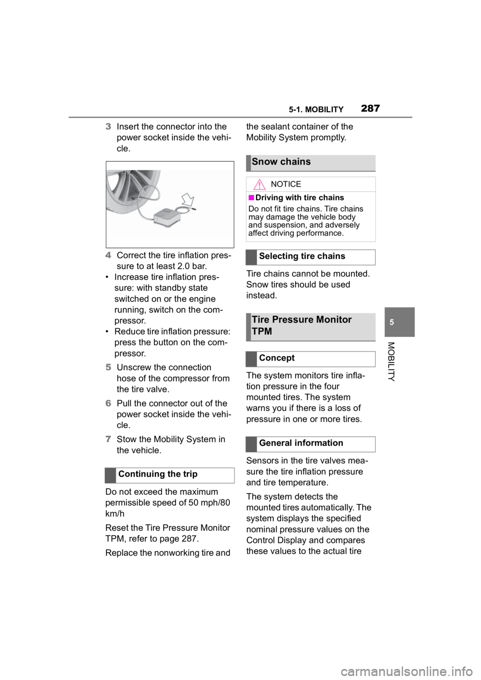
3Insert the connector into the
power socket inside the vehi-
cle.
4 Correct the tire inflation pres-
sure to at least 2.0 bar.
• Increase tire inflation pres- sure: with standby state
switched on or the engine
running, switch on the com-
pressor.
• Reduce tire inflation pressure: press the button on the com-
pressor.
5 Unscrew the connection
hose of the compressor from
the tire valve.
6 Pull the connector out of the
power socket inside the vehi-
cle.
7 Stow the Mobility System in
the vehicle.
Do not exceed the maximum
permissible speed of 50 mph/80
km/h
Reset the Tire Pressure Monitor
TPM, refer to page 287.
Replace the nonworking tire and the sealant container of the
Mobility System promptly.
Tire chains cannot be mounted.
Snow tires should be used
instead.
The system monitors tire infla-
tion pressure in the four
mounted tires. The system
warns you if there is a loss of
pressure in one or more tires.
Sensors in the tire valves mea-
sure the tire inflation pressure
and tire temperature.
The system detects the
mounted tires automatically. The
system displays the specified
nominal pressure values on the
Control Display and compares
these values to the actual tire
Continuing the trip
Snow chains
NOTICE
■Driving with tire chains
Do not fit tire chains. Tire chains
may damage the vehicle body
and suspension, and adversely
affect driving performance.
Selecting tire chains
Tire Pressure Monitor
TPM
Concept
General information
Page 288 of 372

2885-1. MOBILITY
pressure values.
If tires are being used that are
not specified on the tire inflation
pressure details on the vehicle,
refer to page 270, such as tires
with special approval, the sys-
tem needs to be actively reset.
The system will then take over
the actual tire inflation pressures
as the target pressures.
When operating the system,
also note the additional informa-
tion found in the Tire inflation
pressure, refer to page 270.
The following conditions must
be met for the system; other-
wise, reliable flagging of a loss
of tire inflation pressure is not
assured:
• After each tire or wheel change, the system detects and updates the mounted
tires and displays them after a
short trip on the Control Dis-
p l a y.
Enter the inform
ation about the
mounted tires in th e tire settings
when the system does not automat-
ically detect the tires.
• TPM does not activate until
after driving for a few minutes:
• After a tire or wheel replacement.
• Reset, for tires without special approval.
• After changing the tire setting.
• For tires with special approval:
• After a tire or wheel replacement, a reset was perfo rmed with the
correct tire inflation pressure.
• After the tire inflation pressure was adjusted to a new value, a
reset was p erformed.
• Wheels with TPM wheel elec-
tronics.
The information about the
mounted tires can be entered in
the tire settings if the system
does not automatically detect
the tires.
The tire sizes of the mounted
tires can be gathered from the
tire inflation pressure details on
the vehicle, refer to page 270, or
directly on the tires.
Safety information
WARNING
The display of the target pres-
sures is not a sub
stitute for the
tire inflation pressure details on
the vehicle. Incorrect entries in
the tire settings can lead to incor-
rect target tire inflation pressure
values. In this case, it cannot be
guaranteed that the notification of
a loss of tire inflation pressure will
be reliable. There is a risk of injury
and risk of damage to property.
Ensure that the tire sizes of the
mounted tires are displayed cor-
rectly and match the details on the
tires and on the vehicle.
Functional requirements
Tire settings
General information