Page 395 of 586

3936-2. Maintenance
6
Maintenance and care
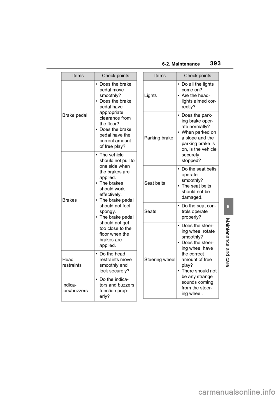
Brake pedal
• Does the brake pedal move
smoothly?
• Does the brake pedal have
appropriate
clearance from
the floor?
• Does the brake pedal have the
correct amount
of free play?
Brakes
• The vehicle should not pull to
one side when
the brakes are
applied.
• The brakes should work
effectively.
• The brake pedal should not feel
spongy.
• The brake pedal should not get
too close to the
floor when the
brakes are
applied.
Head
restraints
• Do the head restraints move
smoothly and
lock securely?
Indica-
tors/buzzers
• Do the indica-tors and buzzers
function prop-
erly?
ItemsCheck points
Lights
• Do all the lights come on?
• Are the head- lights aimed cor-
rectly?
Parking brake
• Does the park-ing brake oper-
ate normally?
• When parked on a slope and the
parking brake is
on, is the vehicle
securely
stopped?
Seat belts
• Do the seat belts operate
smoothly?
• The seat belts should not be
damaged.
Seats
• Do the seat con-trols operate
properly?
Steering wheel
• Does the steer-ing wheel rotate
smoothly?
• Does the steer- ing wheel have
the correct
amount of free
play?
• There should not be any strange
sounds coming
from the steer-
ing wheel.
ItemsCheck points
Page 400 of 586
3986-3. Do-it-yourself maintenance
1Pull the hood lock release
lever.
The hood will pop up slightly.
2Push the auxiliary catch lever
to the left and lift the hood. 3
Hold the hood open by insert-
ing the supporting rod into
the slot.
Hood
Release the lock from the
inside of the vehicle to open
the hood.
Opening the hood
WARNING
■Pre-driving check
Check that the hood is fully closed
and locked.
If the hood is not locked properly,
it may open while the vehicle is in
motion and cause an accident,
which may result i n death or seri-
ous injury.
■To prevent injuries
The support rod may be hot after
driving the vehicle. Touching the
hot support rod may lead to burns
or other serious injuries.
■After installing the support
rod into the slot
Make sure the rod supports the
hood securely fro m falling down
on to your head or body.
Page 410 of 586

4086-3. Do-it-yourself maintenance
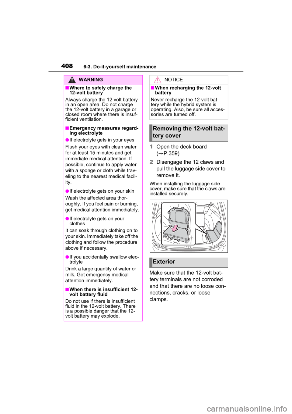
1Open the deck board
( P.359)
2 Disengage the 12 claws and
pull the luggage side cover to
remove it.
When installing the luggage side
cover, make sure that the claws are
installed securely.
Make sure that the 12-volt bat-
tery terminals are not corroded
and that there are no loose con-
nections, cracks, or loose
clamps.
WARNING
■Where to safely charge the
12-volt battery
Always charge the 12-volt battery
in an open area. Do not charge
the 12-volt battery in a garage or
closed room where there is insuf-
ficient ventilation.
■Emergency measures regard-
ing electrolyte
●If electrolyte gets in your eyes
Flush your eyes with clean water
for at least 15 minutes and get
immediate medical attention. If
possible, continue to apply water
with a sponge or cloth while trav-
eling to the nearest medical facil-
ity.
●If electrolyte gets on your skin
Wash the affected area thor-
oughly. If you feel pain or burning,
get medical attention immediately.
●If electrolyte gets on your
clothes
It can soak through clothing on to
your skin. Immediately take off the
clothing and follow the procedure
above if necessary.
●If you accidentally swallow elec-
trolyte
Drink a large quantity of water or
milk. Get emergency medical
attention immediately.
■When there is insufficient 12-
volt battery fluid
Do not use if there is insufficient
fluid in the 12-volt battery. There
is a possible danger that the 12-
volt battery may explode.
NOTICE
■When recharging the 12-volt
battery
Never recharge t he 12-volt bat-
tery while the hybrid system is
operating. Also, be sure all acces-
sories are turned off.
Removing the 12-volt bat-
tery cover
Exterior
Page 432 of 586
4306-3. Do-it-yourself maintenance
driver with a rag.
3Slide the wiper blade to
remove it from the wiper arm.
When installing, rev erse the steps
listed.
■Wiper insert replacement
1 Pull the wiper insert to
remove the claw of the wiper
blade from the stopper, and
pull out the wiper insert. Stopper
Claw
2 Remove the 2 metal plates
from the wiper insert pulled
out, and install the plates to a
new wiper insert.
Make sure that the cutout location
and warp direction of the metal
blades are same as the original.
3Install the wiper insert to the
wiper blade from the side
without the stopper.
4 Secure the stopper of the
wiper insert with the claw of
the wiper blade.
1 Lift up the rear window wiper
arm head cap.
2 Move the wiper blade until a
click sound can be heard and
Rear window wiper
A
B
Page 436 of 586
4346-3. Do-it-yourself maintenance
cover into the key.
5Install the key cover.
Align the key cover with the key
and then press it straight into the
key.
Make sure that the key cover is
securely installed without any gaps
between it and the key.
Vehicles with smart key sys-
tem
1 Release the lock and remove
the mechanical key.
2 Remove the key cover.
Use a screwdriver of an appropriate
size. Forcedly prying may cause the cover damaged.
To prevent damage to the key,
cover the tip of the flathead screw-
driver with a rag.
3
Remove the depleted battery
using a small flathead screw-
driver.
When removing the cover, the elec-
tronic key module may stick to the
cover and the batt ery may not be
visible. In this case, remove the
electronic key module in order to
remove the battery.
When removing the battery, use a
screwdriver of an appropriate size.
Insert a new battery with the “+” ter-
minal facing up.
4 When installing, reverse the
steps listed.
Page 438 of 586
4366-3. Do-it-yourself maintenance
1Turn the power switch to
OFF.
2 Open the fuse box cover.
Engine compartment: Type A
fuse box (if equipped)
Push claws and to com-
pletely release the lock, and then lift
up the cover.
Engine compartment: Type B
fuse box
Push claws and to com-
pletely release the lock, and then lift
up the cover.
Left side instrument panel
Remove the lid.
Right side luggage compart-
ment
Open the deck board. ( P.359)
Disengage the 12 claws and pull
the luggage side cover to remove it.
When installing the luggage side
cover, make sure that the claws are
installed securely.
Remove the cover
Checking and replac-
ing fuses
If any of the electrical com-
ponents do not operate, a
fuse may have blown. If this
happens, check and replace
the fuses as necessary.
Checking and replacing
fuses
AB
AB
Page 439 of 586
4376-3. Do-it-yourself maintenance
6
Maintenance and care
3Remove the fuse.
Only type A fuse can be removed
using the pullout tool.
4Check if the fuse is blown.
Replace the blown fuse with a new
fuse of an appropriate amperage
rating. The amperage rating can be
found on the fuse box lid.
Type A
Normal fuse
Blown fuse
Type BNormal fuse
Blown fuse
Type CNormal fuse
Blown fuse
■After a fuse is replaced
●When installing the lid, make sure
that the tab is ins talled securely.
●If the lights do not turn on even
after the fuse has been replaced,
a bulb may need replacement.
( P.439)
●If the replaced fuse blows again,
have the vehicle inspected by
your Toyota dealer.
■If there is an ove rload in a cir-
cuit
The fuses are designed to blow,
protecting the wiring harness from
damage.A
B
A
B
A
B
Page 446 of 586
4446-3. Do-it-yourself maintenance
pletely secured.
7Reinstall the screws.
8 Reinstall the cover.
■Back-up lights
1 Open the back door and
remove the cover.
To prevent damag e to the cover,
protect the tip of the screwdriver with a rag.
2
Turn the bulb base counter-
clockwise.
Remove the cord from the clip
before turning the bulb base.
3Remove the light bulb.