2023 TOYOTA HIGHLANDER ECU
[x] Cancel search: ECUPage 274 of 552

2744-5. Using the driving support systems
from your vehicle*
●Vehicles which are being over-
taken rapidly by your vehicle*
*
: Depending on the conditions, detection of a vehicle and/or
object may occur.
■Conditions under which the
system may not function cor-
rectly
●In the following situations, vehi-
cles may not be detected correctly
(while driving):
• When the sensor is misaligned
due to a strong impact to the sen-
sor or its surrounding area
• When mud, snow, ice, a sticker,
etc. is covering the sensor or sur-
rounding area on the rear bumper
• When driving on a road surface
that is wet with standing water
during bad weather, such as
heavy rain, snow, or fog
• When multiple vehicles are approaching with only a small gap
between each vehicle
• When the distanc e between your
vehicle and a following vehicle is
short
• When there is a significant differ- ence in speed between your vehi-
cle and the vehicle that enters the
detection area
• When the difference in speed between your vehicle and another
vehicle is changing
• When a vehicle enters a detection area traveling at about the same
speed as your vehicle
• As your vehicle starts from a stop, a vehicle remains in the detection
area
• When driving up and down con- secutive steep inclines, such as
hills, dips in the road, etc.
• When driving on roads with sharp bends, consecutive curves, or
uneven surfaces
• When vehicle lanes are wide, or when driving on the edge of a
lane, and the vehicle in an adja-
cent lane is far away from your vehicle
• When an accessory (such as a bicycle carrier) is installed to the
rear of the vehicle
• When there is a significant differ- ence in height between your vehi-
cle and the vehicle that enters the
detection area
• Immediately after the Blind Spot
Monitor is turned on
• When towing with the vehicle●Instances of unnecessary detec-
tion may increase in situations
such as the following (while driv-
ing):
• When the sensor is misaligned due to a strong impact to the sen-
sor or its surrounding area
• When the distance between your vehicle and a guardrail, wall, etc.
that enters the detection area is
short
• When driving up and down con-
secutive steep inclines, such as
hills, dips in the road, etc.
• When vehicle lanes are narrow, or
when driving on the edge of a
lane, and a vehicle traveling in a
lane other than the adjacent lanes
enters the detection area
• When driving on r oads with sharp
bends, consecutive curves, or
uneven surfaces
• When the tires are slipping or spinning
• When the distance between your vehicle and a following vehicle is
short
• When an accessory (such as a bicycle carrier) is installed to the
rear of the vehicle
• When towing with the vehicle
Page 344 of 552
3445-3. Using the storage features
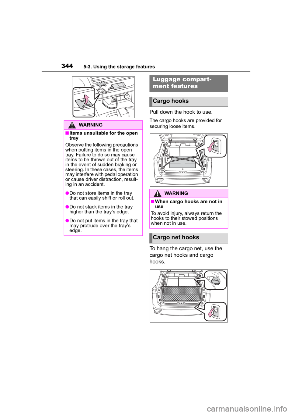
Pull down the hook to use.
The cargo hooks are provided for
securing loose items.
To hang the cargo net, use the
cargo net hooks and cargo
hooks.
WARNING
■Items unsuitable for the open
tray
Observe the following precautions
when putting items in the open
tray. Failure to do so may cause
items to be thrown out of the tray
in the event of sudden braking or
steering. In these cases, the items
may interfere with pedal operation
or cause driver distraction, result-
ing in an accident.
●Do not store items in the tray
that can easily shift or roll out.
●Do not stack items in the tray
higher than the tray’s edge.
●Do not put items in the tray that
may protrude over the tray’s
edge.
Luggage compar t-
ment features
Cargo hooks
WARNING
■When cargo hooks are not in
use
To avoid injury , always return the
hooks to their stowed positions
when not in use.
Cargo net hooks
Page 347 of 552
3475-3. Using the storage features
5
Interior features
cle.
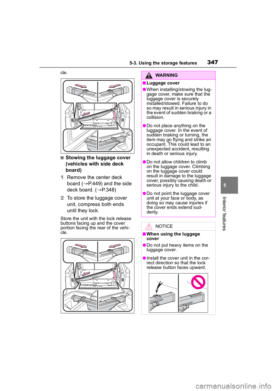
■Stowing the luggage cover
(vehicles with side deck
board)
1 Remove the center deck
board ( P.449) and the side
deck board. ( P.348)
2 To store the luggage cover
unit, compress both ends
until they lock.
Store the unit wit h the lock release
buttons facing up and the cover
portion facing the rear of the vehi-
cle.
WARNING
■Luggage cover
●When installing/stowing the lug-
gage cover, make sure that the
luggage cover is securely
installed/stowed. Failure to do
so may result in serious injury in
the event of sudden braking or a
collision.
●Do not place anything on the
luggage cover. In the event of
sudden braking or turning, the
item may go flying and strike an
occupant. This could lead to an
unexpected accident, resulting
in death or serious injury.
●Do not allow children to climb
on the luggage cover. Climbing
on the luggage cover could
result in damage to the luggage
cover, possibly causing death or
serious injury to the child.
●Do not point the luggage cover
unit at your face or body, as
doing so may cause injuries if
the cover ends extend sud-
denly.
NOTICE
■When using the luggage
cover
●Do not put heavy items on the
luggage cover.
●Install the cover unit in the cor-
rect direction so that the lock
release button faces upward.
Page 360 of 552
3605-4. Using the other interior features
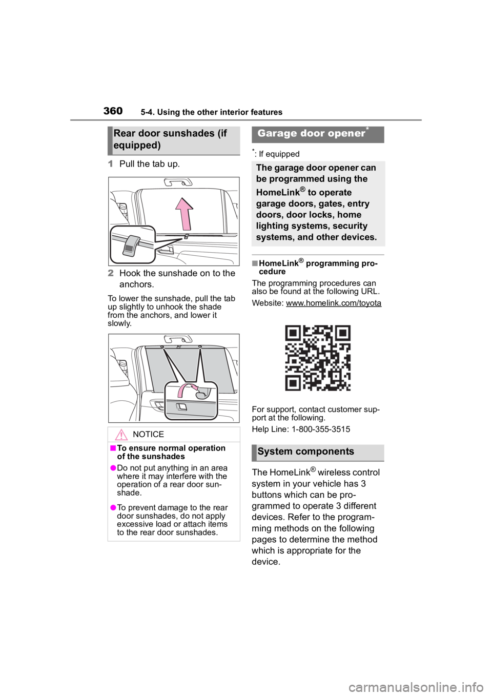
1Pull the tab up.
2 Hook the sunshade on to the
anchors.
To lower the sunshade, pull the tab
up slightly to unhook the shade
from the anchors, and lower it
slowly.
*: If equipped
■HomeLink® programming pro-
cedure
The programming procedures can
also be found at the following URL.
Website: www.homelink.com/toyota
For support, contact customer sup-
port at the following.
Help Line: 1-800-355-3515
The HomeLink® wireless control
system in your vehicle has 3
buttons which can be pro-
grammed to operate 3 different
devices. Refer to the program-
ming methods on the following
pages to determine the method
which is appropriate for the
device.
Rear door sunshades (if
equipped)
NOTICE
■To ensure normal operation
of the sunshades
●Do not put anything in an area
where it may interfere with the
operation of a rear door sun-
shade.
●To prevent damage to the rear
door sunshades, do not apply
excessive load or attach items
to the rear door sunshades.
Garage door opener*
The garage door opener can
be programmed using the
HomeLink
® to operate
garage doors, gates, entry
doors, door locks, home
lighting systems, security
systems, and other devices.
System components
Page 378 of 552

3786-2. Maintenance
General maintenance
Listed below are the general
maintenance items that
should be performed at the
intervals specified in the
“Owner’s Warranty Informa-
tion Booklet” or “Owner’s
Manual Supplement/Sched-
uled Maintenance Guide”. It
is recommended that any
problem you notice should
be brought to the attention
of your Toyota dealer or
qualified service shop for
advice.
WARNING
■If the engine is running
Turn the engine off and ensure
that there is adequate ventilation
before performing maintenance
checks.
Engine compartment
ItemsCheck points
BatteryCheck the connec-
tions. ( P.391)
Brake fluid
Is the brake fluid at
the correct level?
( P.390)
Engine coolant
Is the engine cool-
ant at the correct
level? ( P.389)
Engine oil
Is the engine oil at
the correct level?
( P.386)
Exhaust sys-
temThere should not
be any fumes or
strange sounds.
Radiator/con-
denser
The radiator and
condenser should
be free from for-
eign objects.
( P.390)
Washer fluid
Is there sufficient
washer fluid?
( P.392)
Vehicle interior
ItemsCheck points
Accelerator
pedal
• The accelerator
pedal should
move smoothly
(without uneven
pedal effort or
catching).
Automatic
transmission
“Park” mecha-
nism
• When parked on a slope and the
shift lever is in P,
is the vehicle
securely
stopped?
ItemsCheck points
Page 379 of 552
3796-2. Maintenance
6
Maintenance and care
Brake pedal
• Does the brake pedal move
smoothly?
• Does the brake pedal have
appropriate
clearance from
the floor?
( P.479)
• Does the brake pedal have the
correct amount
of free play?
( P.479)
Brakes
• The vehicle
should not pull to
one side when
the brakes are
applied.
• The brakes should work
effectively.
• The brake pedal should not feel
spongy.
• The brake pedal should not get
too close to the
floor when the
brakes are
applied.
Head
restraints
• Do the head restraints move
smoothly and
lock securely?
Horn• Works properly?
Indica-
tors/buzzers
• Do the indica-tors and buzzers
function prop-
erly?
ItemsCheck points
Lights
• Do all the lights come on?
• Are the head- lights aimed cor-
rectly? (P.414)
Parking brake
• Does the park-ing brake switch
operate nor-
mally?
• When parked on a slope and the
parking brake is
on, is the vehicle
securely
stopped?
Seat belts
• Do the seat belts operate
smoothly?
• The seat belts should not be
damaged.
Seats
• Do the seat con-trols operate
properly?
Steering wheel
• Does the steer-ing wheel rotate
smoothly?
• Does the steer- ing wheel have
the correct
amount of free
play?
• There should not be any strange
sounds coming
from the steer-
ing wheel.
ItemsCheck points
Page 384 of 552

3846-3. Do-it-yourself maintenance
1Pull the hood lock release
lever.
The hood will pop up slightly.
2Pull up the auxiliary catch
lever and lift the hood.
3 Hold the hood open by insert-
ing the support rod into the
slot.
Hood
Opening the hood
WARNING
■Pre-driving check
Check that the hood is fully closed
and locked.
If the hood is not locked properly,
it may open while the vehicle is in
motion and cause an accident,
which may result i n death or seri-
ous injury.
■To prevent a injuries
The support rod may be hot after
driving the vehicle. Touching the
hot support rod may lead to burns
or other serious injuries.
■After installing the support
rod into the slot
Make sure the rod supports the
hood securely preventing it from
falling down onto your head or
body.
NOTICE
■When the hood is open
Even if the engine switch is turned
off, the cooling fan may continue
to operate for a short time. When
the cooling fan is rotating, do not
touch or approac h the inside of
the engine compartment.
■When closing the hood
Be sure to return the support rod
to its clip before closing the hood.
Closing the hood with the support
rod not clipped could cause the
hood to bend.
Page 417 of 552
4176-3. Do-it-yourself maintenance
6
Maintenance and care
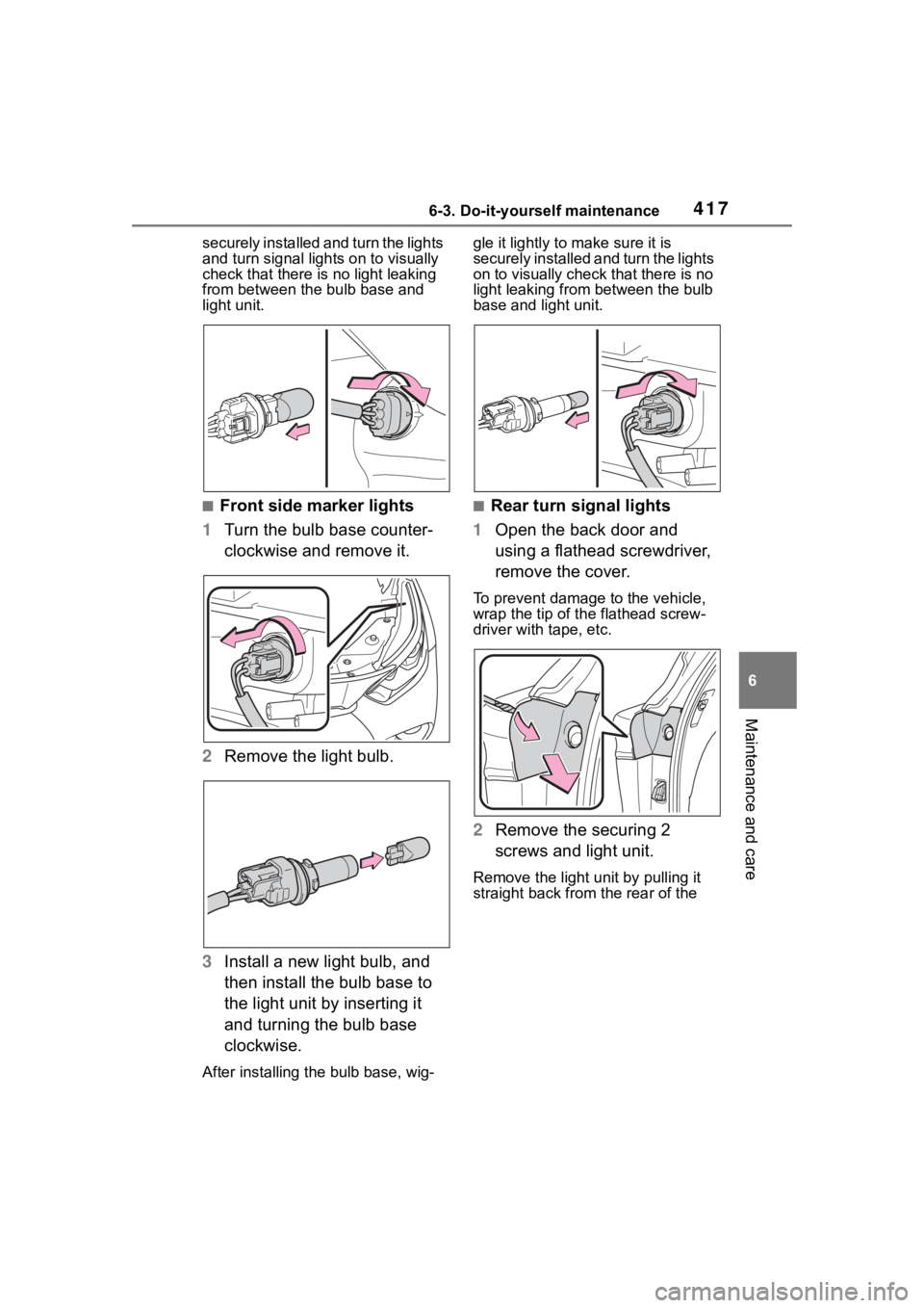
securely installed and turn the lights
and turn signal lights on to visually
check that there is no light leaking
from between the bulb base and
light unit.
■Front side marker lights
1 Turn the bulb base counter-
clockwise and remove it.
2 Remove the light bulb.
3 Install a new light bulb, and
then install the bulb base to
the light unit by inserting it
and turning the bulb base
clockwise.
After installing th e bulb base, wig- gle it lightly to make sure it is
securely installed a
nd turn the lights
on to visually check that there is no
light leaking from between the bulb
base and light unit.
■Rear turn signal lights
1 Open the back door and
using a flathead screwdriver,
remove the cover.
To prevent damage to the vehicle,
wrap the tip of th e flathead screw-
driver with tape, etc.
2 Remove the securing 2
screws and light unit.
Remove the light u nit by pulling it
straight back from the rear of the