2023 NISSAN PATHFINDER brake light
[x] Cancel search: brake lightPage 505 of 665

If the chassis control system error warning
message appears in the vehicle informa-
tion display, it may indicate that the ARC is
not functioning properly. Have the system
checked as soon as possible. It is recom-
mended that you visit a NISSAN dealer for
this service.
WARNING
The ARC may not be effective depend-
ing on the driving condition. Always
drive carefully and attentively.
When the ARC is operating, you may feel a
pulsation in the brake pedal and hear a
noise. This is normal and indicates that the
ARC is operating properly. You may also feel
deceleration when the ARC is operating.
However, this is not a malfunction.
WARNING
• Never rely solely on the hill descent
control system to control vehicle
speed when driving on steep down-
hill grades. Always drive carefully and
attentively when using the hill de-
scent control system and decelerate
the vehicle speed by depressing the
brake pedal if necessary. Be espe-
cially careful when driving on frozen,
muddy or extremely steep downhill
roads. Failure to control vehicle
speed may result in a loss of control
of the vehicle and possible serious
injury or death.
• The hill descent control may not con-
trol the vehicle speed on a hill under
all load or road conditions. Always be
prepared to depress the brake pedal
to control vehicle speed. Failure to do
so may result in a collision or serious
personal injury. The hill descent control system helps
maintain vehicle speed when driving under
15 mph (25 km/h) on steeper downhill
grades. Hill descent control is useful when
engine braking alone cannot control ve-
hicle speed. Hill descent control applies the
vehicle brakes to control vehicle speed al-
lowing the driver to concentrate on steer-
ing while reducing the burden of brake and
accelerator operation. The hill descent
control system will only work in the Sand
and Mud/Rut mode.
If the hill descent control system ON indica-
tor light is blinking, the hill descent control
is engaged; however, the hill descent con-
trol will not control the vehicle speed.
• Once the system is activated, the indica-
tor light will remain on in the instrument
panel. For additional information, see “Hill
descent control system ON indicator
light” (P. 2-18).
If the accelerator or brake pedal is de-
pressed while the hill descent control sys-
tem is on, the system will stop operating
temporarily. As soon as the accelerator or
brake pedal is released, the hill descent
control system begins to function again if
the hill descent control operating condi-
tions are fulfilled.
HILL DESCENT CONTROL SYSTEM (if
so equipped)
5-182Starting and driving
Page 513 of 665

•When the front defroster switch is on.
• When the rear window defroster switch
is on.
• When the temperature inside the ve-
hicle is lower than approximately 20°C
(68°F), unless the Air Conditioning ECO
customize option is selected, and the
ECO driving mode is on.
• When the temperature inside the ve-
hicle is higher than approximately 30°C
(86°F), unless the Air Conditioning ECO
customize option is selected, and the
ECO driving mode is on. (When the air
conditioner is off, the Idling Stop Sys-
tem will operate.)
• When the fan speed of the air condi-
tioner is set to the maximum speed,
unless the Air Conditioning ECO cus-
tomize option is selected, and the ECO
driving mode is on.
• When the Idling Stop OFF switch is
turned on.
• When the power consumption is large.
• When the altitude is high.
• When the accelerator pedal is
depressed.
• When the shif t lever is in any range
other than D (Drive). •
When the brake pedal is not firmly
depressed.
• When stopping the vehicle on steep
sloping roads.
NOTE:
The Idling Stop System may not activate
when the Intelligent Key is not in the ve-
hicle and you open/close any door.
The engine will not restart even if the
brake pedal is released while the Idling
Stop System is activated under the fol-
lowing conditions: (The engine may re-
start under other conditions.)
• When the automatic brake hold system
is activated.
• When the engine hood is opened.
NOTE:
It may take some time until the Idling
Stop System activates under the follow-
ing conditions:
•When the battery is discharged.
• When the outside temperature is low or
high.
• When the battery is replaced or the
battery terminal is disconnected for
extended periods and then
reconnected.
NOTE:
When the Idling Stop System indicator
light illuminates, the engine starts run-
ning automatically under at least one of
the following conditions:
• The vacuum pressure for the brake sys-
tem is not enough as the brake pedal is
repeatedly depressed.
• The driver’s seat belt is unfastened, or
the driver’s door is open.
• The battery voltage becomes low (due
to electrical load from other vehicle
systems like headlights, heaters, etc.,
or auxiliary devices connected to the 12
volt socket inside the vehicle).
• The vehicle speed is above about 1 mph
(2 km/h).
• When the rear window defroster is
operated.
• When the temperature inside the ve-
hicle is lower than approximately 68°F
(20°C), unless the Air Conditioning ECO
customize option is selected, and the
ECO driving mode is on.
5-190Starting and driving
Page 514 of 665

•When the temperature inside the ve-
hicle is higher than approximately 86°F
(30°C), unless the Air Conditioning ECO
customize option is selected, and the
ECO driving mode is on. (When the air
conditioner is off, the Idling Stop Sys-
tem will operate.)
• When the front defroster is turned on.
• When more than 3 minutes have
elapsed since the Idling Stop System
was active.
• When the accelerator pedal is
depressed.
• When the steering wheel is operated.
(The steering wheel operation may be-
come heavy, but this is not a
malfunction.)
• When the battery capacity is low.
• When the power consumption is high.
• When the shif t lever is in any range
other than D (Drive).
• When the Idling Stop OFF switch is
pushed.
• When the negative pressure of the
brake system is not sufficiently applied
by depressing the brake pedal several
times.NOTE:
The Idling Stop System may not activate
when the Intelligent Key is not in the ve-
hicle and you open/close any door.
NOTE:
The following condition will prevent the
Idling Stop System from automatically
restarting the engine. Starting the en-
gine with the ignition switch operation is
then necessary:
• The hood is open.
Use this system while waiting at a stop
light, etc. When the vehicle is stopped for
long periods of time, turn off the engine.
When the engine is stopped by the Idling
Stop System, heating, cooling and dehu-
midif ying functions will be deactivated. To
avoid the air conditioning functions from
being deactivated, turn off the Idling Stop
System by pushing the Idling Stop OFF
switch.
RETROGRADE MOVEMENT
CONTROL FUNCTION
This system is designed to reduce the ret-
rograde movement that occurs while the
driver’s foot changes from depressing the
brake pedal to the accelerator pedal when
moving the vehicle while the Idling Stop
System is active on a hilly road.
IDLING STOP SYSTEM DISPLAY
The status of the Idling Stop System can be
checked in the vehicle information display.
Starting and driving5-191
Page 533 of 665
•Whenever working on or near a bat-
tery, always wear suitable eye pro-
tectors (for example, goggles or in-
dustrial safety spectacles) and
remove rings, metal bands, or any
other jewelry. Do not lean over the
battery when jump starting.
• Do not attempt to jump start a frozen
battery. It could explode and cause
serious injury.
• Your vehicle has an automatic engine
cooling fan. It could come on at any
time. Keep hands and other objects
away from it.
WARNING
Always follow the instructions below.
Failure to do so could result in damage
to the charging system and cause per-
sonal injury.
1. If the booster battery is in another ve- hicle, position the two vehicles to bring
their batteries near each other.
Do not allow the two vehicles to touch.
2. Apply the parking brake. Push the park button to shif t to the P (Park) position.
Switch off all unnecessary electrical sys-
tems (lights, heater, air conditioner, etc.). 3. Place the ignition switch to the LOCK or
OFF position.
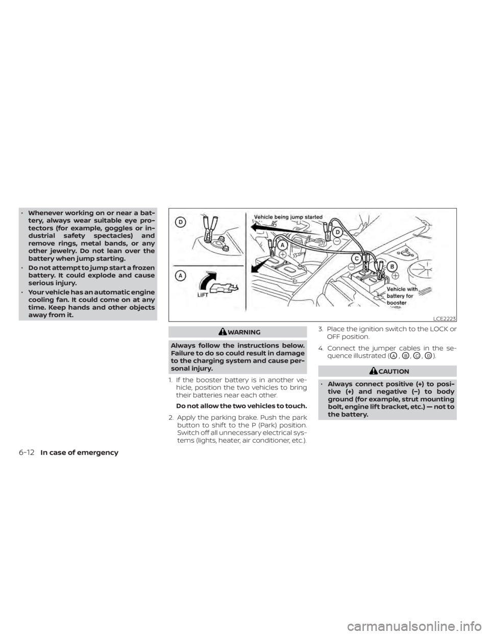
4. Connect the jumper cables in the se- quence illustrated (
OA,OB,OC,OD).
CAUTION
• Always connect positive (+) to posi-
tive (+) and negative (−) to body
ground (for example, strut mounting
bolt, engine lif t bracket, etc.) — not to
the battery.
LCE2223
6-12In case of emergency
Page 548 of 665

8 Do-it-yourself
Maintenance precautions.......................8-2
Engine compartment check locations ...........8-3
Engine cooling system ..........................8-4
Checking engine coolant level ................8-5
Changing engine coolant ....................8-5
Engine oil .......................................8-6
Checking engine oil level .....................8-6
Changing engine oil and oil filter ..............8-6
Automatic Transmission Fluid (ATF) .............8-10
Brake fluid ....................................... 8-11
Windshield-washer fluid .........................8-11
Windshield-washer fluid reservoir ............8-11
Battery......................................... 8-13
Jump starting ............................... 8-14
Variable voltage control system ................8-15
Drive belt ....................................... 8-15
Spark plugs .................................... 8-16
Replacing spark plugs .......................8-16
Air cleaner ..................................... 8-17
In-cabin microfilter .......................... 8-17Windshield wiper blades
........................8-18
Cleaning .................................... 8-18
Replacing ................................... 8-18
Brakes ......................................... 8-20
Fuses .......................................... 8-20
Engine compartment ....................... 8-21
Passenger compartment ...................8-22
Battery replacement ........................... 8-24
NISSAN Intelligent Key® ......................8-24
Lights .......................................... 8-26
Headlights .................................. 8-26
Fog lights (if so equipped) ...................8-26
Exterior and interior lights ...................8-26
Wheels and tires ............................... 8-28
Tire pressure ................................ 8-28
Tire labeling ................................. 8-33
Types of tires ................................ 8-37
Tire chains .................................. 8-38
Changing
wheels and tires .................. 8-39
Page 558 of 665
WARNING
• Use only new fluid from a sealed con-
tainer. Old, inferior or contaminated
fluid may damage the brake system.
The use of improper fluids can dam-
age the brake system and affect the
vehicle's stopping ability.
• Clean the filler cap before removing.
• Brake fluid is poisonous and should
be stored carefully in marked con-
tainers out of reach of children.
CAUTION
Do not spill the fluid on any painted sur-
faces. This will damage the paint. If fluid
is spilled, immediately wash the sur-
face with water.
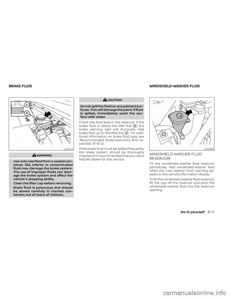
Check the fluid level in the reservoir. If the
brake fluid is below the MIN line
OB, the
brake warning light will illuminate. Add
brake fluid up to the MAX line
OA. For addi-
tional information on brake fluid type, see
“Recommended fluids/lubricants and ca-
pacities” (P. 10-2).
If the brake fluid must be added frequently,
the brake system should be thoroughly
checked. It is recommended that you visit a
NISSAN dealer for this service.
WINDSHIELD-WASHER FLUID
RESERVOIR
Fill the windshield-washer fluid reservoir
periodically. Add windshield-washer fluid
when the “Low Washer Fluid” warning ap-
pears in the vehicle information display.
To fill the windshield-washer fluid reservoir,
lif t the cap off the reservoir and pour the
windshield-washer fluid into the reservoir
opening.
LDI2147LDI2583
BRAKE FLUID WINDSHIELD-WASHER FLUID
Do-it-yourself8-11
Page 567 of 665

If the brakes do not operate properly have
the brakes checked. It is recommended
that you visit a NISSAN dealer for this
service.
Self-adjusting brakes
Your vehicle is equipped with self-adjusting
brakes.
The front and rear disc-type brakes self-
adjust every time the brake pedal is
applied.
WARNING
Have your brake system checked if the
brake pedal height does not return to
normal. It is recommended that you
visit a NISSAN dealer for this service.
Brake pad wear indicators
The disc brake pads on your vehicle have
audible wear indicators. When a brake pad
requires replacement, a high pitched
scraping or screeching sound will be heard
when the vehicle is in motion. The noise will
be heard whether or not the brake pedal is
depressed. Have the brakes checked as
soon as possible if the wear indicator
sound is heard. Under some driving or climate conditions,
occasional brake squeak, squeal or other
noise may be heard. Occasional brake
noise during light to moderate stops is nor-
mal and does not affect the function or
performance of the brake system.
Proper brake inspection intervals should
be followed.
For additional information re-
garding brake inspections, see appropriate
maintenance schedule information in the
"Maintenance and schedules" section of
this manual.
If any electrical equipment does not oper-
ate, check for an open fuse.
Fuses are used in the passenger and en-
gine compartment. Spare fuses are pro-
vided and can be found in the passenger
compartment fuse box.
When installing a fuse make sure the fuse is
installed in the fuse box securely.
LDI2997
BRAKES FUSES
8-20Do-it-yourself
Page 588 of 665

•If the wheels are changed for any
reason, always replace with wheels
which have the same off-set dimen-
sion. Wheels of a different off-set
could cause premature tire wear, de-
grade vehicle handling characteris-
tics, affect the VDC system and/or in-
terference with the brake discs. Such
interference can lead to decreased
braking efficiency and/or early brake
pad wear. For additional information
on wheel off-set dimensions, see
“Wheels and tires” (P. 10-10).
• When using a wheel without the
TPMS such as the spare tire, the TPMS
will not function and the low tire
pressure warning light will flash for
approximately 1 minute. The light will
remain on af ter 1 minute. Have your
tires replaced and/or TPMS system
reset as soon as possible. It is recom-
mended that you visit a NISSAN
dealer for this service.
• Replacing tires with those not origi-
nally specified by NISSAN could af-
fect the proper operation of the
TPMS.
• The TPMS sensor may be damaged if
it is not handled correctly. Be careful
when handling the TPMS sensor. •
When replacing the TPMS sensor, the
ID registration may be required. It is
recommended that you visit a
NISSAN dealer for ID registration.
• Do not use a valve stem cap that is
not specified by NISSAN. The valve
stem cap may become stuck.
• Be sure that the valve stem caps are
correctly fitted. Otherwise the valve
may be clogged up with dirt and
cause a malfunction or loss of
pressure.
• Do not install a damaged or de-
formed wheel or tire even if it has
been repaired. Such wheels or tires
could have structural damage and
could fail without warning.
• The use of retread tires is not
recommended.
• For additional information regarding
tires, refer to “Important Tire Safety
Information” (US) or “Tire Safety In-
formation” (Canada) in the Warranty
Information Booklet.Four-wheel drive models
CAUTION
• Always use tires of the same type,
size, brand, construction (bias, bias-
belted or radial), and tread pattern on
all four wheels. Failure to do so may
result in a circumference difference
between tires on the front and rear
axles which will cause excessive tire
wear and may damage the transmis-
sion and the drivetrain parts.
• Only use the spare tire specified for
your vehicle.
If excessive tire wear is found, it is recom-
mended that all four tires be replaced with
tires of the same size, brand, construction
and tread pattern. The tire pressure and
wheel alignment should also be checked
and corrected as necessary. It is recom-
mended that you visit a NISSAN dealer for
this service.
Wheel balance
Unbalanced wheels may affect vehicle
handling and tire life. Even with regular use,
wheels can get out of balance. Therefore,
they should be balanced as required.
Do-it-yourself8-41