2023 NISSAN KICKS sensor
[x] Cancel search: sensorPage 395 of 558
WARNING
Listed below are the system limitations
for the I-FCW system. Failure to operate
the vehicle in accordance with these
system limitations could result in seri-
ous injury or death.
• The I-FCW system cannot detect all
vehicles under all conditions. •
The radar sensor does not detect the
following objects:
– Pedestrians, animals or obstacles
in the roadway
– Oncoming vehicles
– Crossing vehicles
• (Illustration A) The I-FCW system
does not function when a vehicle
ahead is a narrow vehicle, such as a
motorcycle. •The radar sensor may not detect a ve-
hicle ahead in the following conditions:
– Snow or heavy rain
– Dirt, ice, snow or other material
covering the radar sensor.
–
Interference by other radar sources.
– Snow or road spray from traveling
vehicles.
– Driving in a tunnel
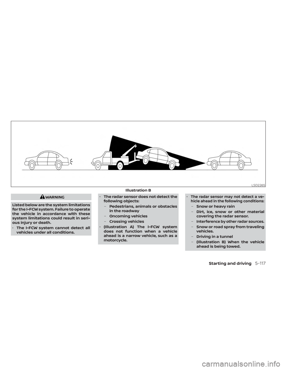
– (Illustration B) When the vehicle
ahead is being towed.
LSD2265
Illustration B
Starting and driving5-117
Page 396 of 558
–(Illustration C) When the distance
to the vehicle ahead is too close,
the beam of the radar sensor is
obstructed.
– (Illustration D) When driving on a
steep downhill slope or roads with
sharp curves.
• The system is designed to automati-
cally check the sensor’s functionality,
within certain limitations. The sys-
tem may not detect some forms of
obstruction of the sensor area such
as ice, snow, stickers, etc. In these
cases, the system may not be able to
warn the driver properly. Be sure that
you check, clean and clear the sensor
area regularly.
• Excessive noise will interfere with the
warning chime sound, and the chime
may not be heard.
5-118Starting and driving
Page 399 of 558
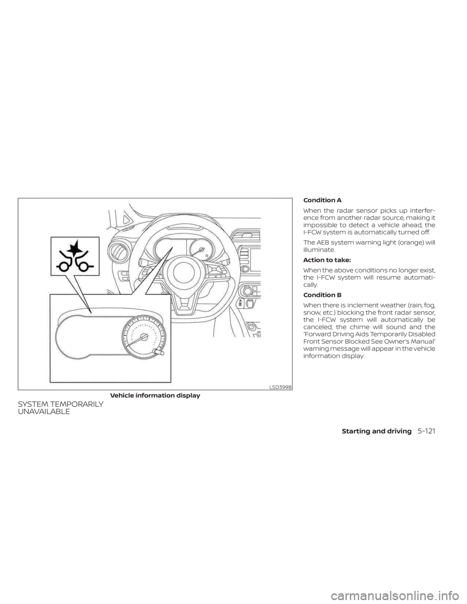
SYSTEM TEMPORARILY
UNAVAILABLE
Condition A
When the radar sensor picks up interfer-
ence from another radar source, making it
impossible to detect a vehicle ahead, the
I-FCW system is automatically turned off.
The AEB system warning light (orange) will
illuminate.
Action to take:
When the above conditions no longer exist,
the I-FCW system will resume automati-
cally.
Condition B
When there is inclement weather (rain, fog,
snow, etc.) blocking the front radar sensor,
the I-FCW system will automatically be
canceled, the chime will sound and the
“Forward Driving Aids Temporarily Disabled
Front Sensor Blocked See Owner’s Manual”
warning message will appear in the vehicle
information display.
LSD3998
Vehicle information display
Starting and driving5-121
Page 400 of 558
Action to take:
When the conditions listed above are no
longer present, the warning message will
no longer be available in the vehicle infor-
mation display. If the “Forward Driving Aids
Temporarily Disabled Front Sensor Blocked
See Owner’s Manual” warning message
continues to be displayed, have the system
checked. It is recommended that you visit a
NISSAN dealer for this service.
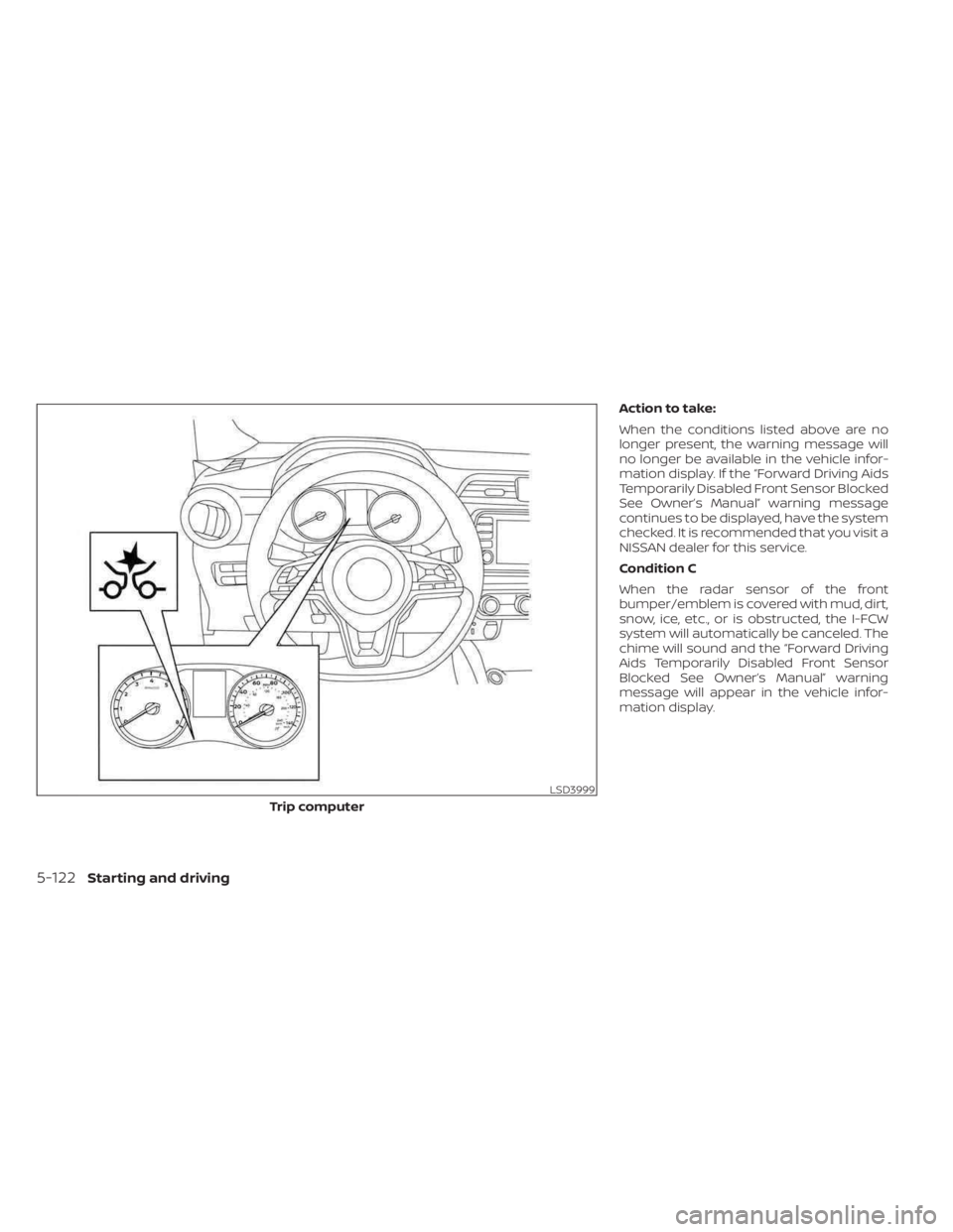
Condition C
When the radar sensor of the front
bumper/emblem is covered with mud, dirt,
snow, ice, etc., or is obstructed, the I-FCW
system will automatically be canceled. The
chime will sound and the “Forward Driving
Aids Temporarily Disabled Front Sensor
Blocked See Owner’s Manual” warning
message will appear in the vehicle infor-
mation display.
LSD3999
Trip computer
5-122Starting and driving
Page 401 of 558
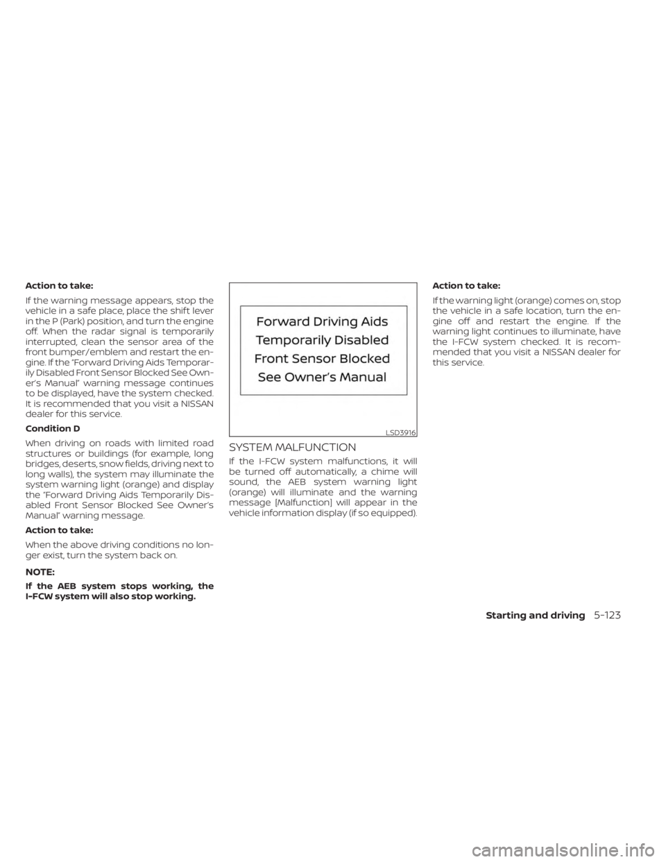
Action to take:
If the warning message appears, stop the
vehicle in a safe place, place the shif t lever
in the P (Park) position, and turn the engine
off. When the radar signal is temporarily
interrupted, clean the sensor area of the
front bumper/emblem and restart the en-
gine. If the “Forward Driving Aids Temporar-
ily Disabled Front Sensor Blocked See Own-
er’s Manual” warning message continues
to be displayed, have the system checked.
It is recommended that you visit a NISSAN
dealer for this service.
Condition D
When driving on roads with limited road
structures or buildings (for example, long
bridges, deserts, snow fields, driving next to
long walls), the system may illuminate the
system warning light (orange) and display
the “Forward Driving Aids Temporarily Dis-
abled Front Sensor Blocked See Owner’s
Manual” warning message.
Action to take:
When the above driving conditions no lon-
ger exist, turn the system back on.
NOTE:
If the AEB system stops working, the
I-FCW system will also stop working.
SYSTEM MALFUNCTION
If the I-FCW system malfunctions, it will
be turned off automatically, a chime will
sound, the AEB system warning light
(orange) will illuminate and the warning
message [Malfunction] will appear in the
vehicle information display (if so equipped).Action to take:
If the warning light (orange) comes on, stop
the vehicle in a safe location, turn the en-
gine off and restart the engine. If the
warning light continues to illuminate, have
the I-FCW system checked. It is recom-
mended that you visit a NISSAN dealer for
this service.
LSD3916
Starting and driving5-123
Page 402 of 558
SYSTEM MAINTENANCE
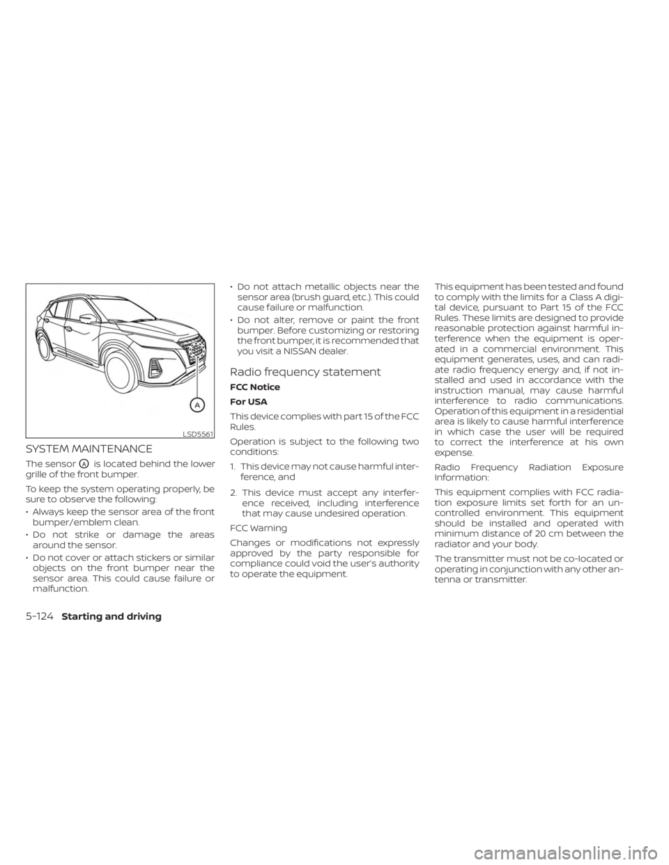
The sensorOAis located behind the lower
grille of the front bumper.
To keep the system operating properly, be
sure to observe the following:
• Always keep the sensor area of the front bumper/emblem clean.
• Do not strike or damage the areas around the sensor.
• Do not cover or attach stickers or similar objects on the front bumper near the
sensor area. This could cause failure or
malfunction. • Do not attach metallic objects near the
sensor area (brush guard, etc.). This could
cause failure or malfunction.
• Do not alter, remove or paint the front bumper. Before customizing or restoring
the front bumper, it is recommended that
you visit a NISSAN dealer.
Radio frequency statement
FCC Notice
For USA
This device complies with part 15 of the FCC
Rules.
Operation is subject to the following two
conditions:
1. This device may not cause harmful inter- ference, and
2. This device must accept any interfer- ence received, including interference
that may cause undesired operation.
FCC Warning
Changes or modifications not expressly
approved by the party responsible for
compliance could void the user’s authority
to operate the equipment. This equipment has been tested and found
to comply with the limits for a Class A digi-
tal device, pursuant to Part 15 of the FCC
Rules. These limits are designed to provide
reasonable protection against harmful in-
terference when the equipment is oper-
ated in a commercial environment. This
equipment generates, uses, and can radi-
ate radio frequency energy and, if not in-
stalled and used in accordance with the
instruction manual, may cause harmful
interference to radio communications.
Operation of this equipment in a residential
area is likely to cause harmful interference
in which case the user will be required
to correct the interference at his own
expense.
Radio Frequency Radiation Exposure
Information:
This equipment complies with FCC radia-
tion exposure limits set forth for an un-
controlled environment. This equipment
should be installed and operated with
minimum distance of 20 cm between the
radiator and your body.
The transmitter must not be co-located or
operating in conjunction with any other an-
tenna or transmitter.
LSD5561
5-124Starting and driving
Page 411 of 558
•Tire type and condition may also af-
fect braking effectiveness.
– When replacing tires, install the
specified size of tires on all four
wheels.
–
When installing a spare tire, make sure that it is the proper size and
type as specified on the Tire and
Loading Information label. For ad-
ditional information, see “Tire and
Loading Information label” (P. 8-30).
– For additional information, see
“Wheels and tires” (P. 8-28).
The ABS controls the brakes so the wheels
do not lock during hard braking or when
braking on slippery surfaces. The system
detects the rotation speed at each wheel
and varies the brake fluid pressure to pre-
vent each wheel from locking and sliding.
By preventing each wheel from locking, the
system helps the driver maintain steering
control and helps to minimize swerving
and spinning on slippery surfaces.
Using the system
Depress the brake pedal and hold it down.
Depress the brake pedal with firm steady
pressure, but do not pump the brakes. The
Anti-lock Braking System will operate to
prevent the wheels from locking up. Steer
the vehicle to avoid obstacles.
WARNING
Do not pump the brake pedal. Doing so
may result in increased stopping
distances.
Self-test feature
The Anti-lock Braking System (ABS) in-
cludes electronic sensors, electric pumps,
hydraulic solenoids and a computer. The
computer has a built-in diagnostic feature
that tests the system each time you start
the engine and move the vehicle at a low
speed in forward or reverse. When the self-
test occurs, you may hear a “clunk” noise
and/or feel a pulsation in the brake pedal.
This is normal and does not indicate a
malfunction. If the computer senses a mal-
function, it switches the ABS off and illumi-
nates the ABS warning light on the instru- ment panel. The brake system then
operates normally but without anti-lock
assistance.
If the ABS warning light illuminates during
the self-test or while driving, have the ve-
hicle checked. It is recommended that you
visit a NISSAN dealer for this service.
Normal operation
The Anti-lock Braking System (ABS) oper-
ates at speeds abov
e3-6mph(5-10
km/h). The speed varies according to road
conditions.
When the ABS senses that one or more
wheels are close to locking up, the actuator
rapidly applies and releases hydraulic pres-
sure. This action is similar to pumping the
brakes very quickly. You may feel a pulsa-
tion in the brake pedal and hear a noise
from under the hood or feel a vibration
from the actuator when it is operating. This
is normal and indicates that the ABS is op-
erating properly. However, the pulsation
may indicate that road conditions are haz-
ardous and extra care is required while
driving.
Starting and driving5-133
Page 412 of 558
BRAKE ASSIST
When the force applied to the brake pedal
exceeds a certain level, the Brake Assist is
activated generating greater braking force
than a conventional brake booster even
with light pedal force.
WARNING
The Brake Assist is only an aid to assist
braking operation and is not a collision
warning or avoidance device. It is the
driver’s responsibility to stay alert,
drive safely and be in control of the ve-
hicle at all times. The VDC system uses various sensors to
monitor driver inputs and vehicle motion.
Under certain driving conditions, the VDC
system helps to perform the following
functions:
• Controls brake pressure to reduce wheel
slip on one slipping drive wheel so power
is transferred to a non-slipping drive
wheel on the same axle.
• Controls brake pressure and engine out- put to reduce drive wheel slip based on
vehicle speed (traction control function).
• Controls brake pressure at individual wheels and engine output to help the
driver maintain control of the vehicle in
the following conditions:– Understeer (vehicle tends to not follow the steered path despite increased
steering input)
– Oversteer (vehicle tends to spin due to certain road or driving conditions)
The VDC system can help the driver to
maintain control of the vehicle, but it can-
not prevent loss of vehicle control in all driv-
ing situations. When the VDC system operates, the
indicator light in the instrument panel
flashes so note the following:
• The road may be slippery or the system
may determine some action is required
to help keep the vehicle on the steered
path.
• You may feel a pulsation in the brake pedal and hear a noise or vibration from
under the hood. This is normal and indi-
cates that the VDC system is working
properly.
• Adjust your speed and driving to the road conditions.
For additional information, see “Slip indica-
tor light” (P. 2-21) and ”Vehicle Dynamic Con-
trol (VDC) OFF indicator light” (P. 2-21).
If a malfunction occurs in the system, the
indicator light comes on in the instru-
ment panel. The VDC system automatically
turns off when these indicator lights are on.
The VDC OFF switch, or the vehicle infor-
mation display, is used to turn off the VDC
system. The
indicator light and the
Automatic Emergency Braking (AEB) sys-
tem warning light or the AEB with Pedes-
trian Detection system warning light illumi-
nate to indicate the VDC system is off.
VEHICLE DYNAMIC CONTROL (VDC)
SYSTEM
5-134Starting and driving