2023 NISSAN KICKS charging
[x] Cancel search: chargingPage 252 of 558
iPod®* PLAYER OPERATION
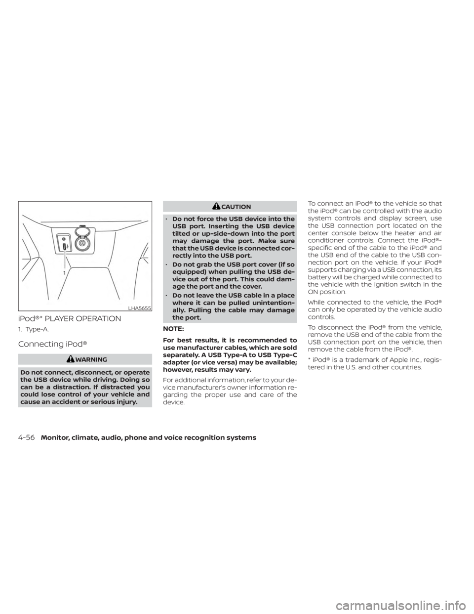
1. Type-A.
Connecting iPod®
WARNING
Do not connect, disconnect, or operate
the USB device while driving. Doing so
can be a distraction. If distracted you
could lose control of your vehicle and
cause an accident or serious injury.
CAUTION
• Do not force the USB device into the
USB port. Inserting the USB device
tilted or up-side-down into the port
may damage the port. Make sure
that the USB device is connected cor-
rectly into the USB port.
• Do not grab the USB port cover (if so
equipped) when pulling the USB de-
vice out of the port. This could dam-
age the port and the cover.
• Do not leave the USB cable in a place
where it can be pulled unintention-
ally. Pulling the cable may damage
the port.
NOTE:
For best results, it is recommended to
use manufacturer cables, which are sold
separately. A USB Type-A to USB Type-C
adapter (or vice versa) may be available;
however, results may vary.
For additional information, refer to your de-
vice manufacturer’s owner information re-
garding the proper use and care of the
device. To connect an iPod® to the vehicle so that
the iPod® can be controlled with the audio
system controls and display screen, use
the USB connection port located on the
center console below the heater and air
conditioner controls. Connect the iPod®-
specific end of the cable to the iPod® and
the USB end of the cable to the USB con-
nection port on the vehicle. If your iPod®
supports charging via a USB connection, its
battery will be charged while connected to
the vehicle with the ignition switch in the
ON position.
While connected to the vehicle, the iPod®
can only be operated by the vehicle audio
controls.
To disconnect the iPod® from the vehicle,
remove the USB end of the cable from the
USB connection port on the vehicle, then
remove the cable from the iPod®.
* iPod® is a trademark of Apple Inc., regis-
tered in the U.S. and other countries.
LHA5655
4-56Monitor, climate, audio, phone and voice recognition systems
Page 262 of 558
When installing a CB, ham radio or car
phone in your vehicle, be sure to observe
the following precautions; otherwise, the
new equipment may adversely affect the
engine control system and other electronic
parts.
WARNING
• A cellular phone should not be used
for any purpose while driving so full
attention may be given to vehicle op-
eration. Some jurisdictions prohibit
the use of cellular phones while
driving.
• If you must make a call while your
vehicle is in motion, the hands free
cellular phone operational mode (if
so equipped) is highly recom-
mended. Exercise extreme caution at
all times so full attention may be
given to vehicle operation.
• If you are unable to devote full atten-
tion to vehicle operation while talk-
ing on the phone, pull off the road to
a safe location and stop your vehicle.
CAUTION
• Keep the antenna as far away as pos-
sible from the electronic control
modules.
• Keep the antenna wire more than 8 in
(20 cm) away from the electronic
control system harnesses. Do not
route the antenna wire next to any
harness.
• Adjust the antenna standing-wave
ratio as recommended by the
manufacturer.
• Connect the ground wire from the CB
radio chassis to the body.
• For additional information, it is rec-
ommended that you visit a NISSAN
dealer.WARNING
• Use a phone af ter stopping your ve-
hicle in a safe location. If you have to
use a phone while driving, exercise
extreme caution at all times so full
attention may be given to vehicle
operation.
• If you are unable to devote full atten-
tion to vehicle operation while talk-
ing on the phone, pull off the road to
a safe location and stop your vehicle.
CAUTION
To avoid discharging the vehicle bat-
tery, use a phone af ter starting the
engine.
CAR PHONE OR CB RADIO BLUETOOTH® HANDS-FREE PHONE
SYSTEM
4-66Monitor, climate, audio, phone and voice recognition systems
Page 437 of 558
WARNING
Always follow the instructions below.
Failure to do so could result in damage
to the charging system and cause per-
sonal injury.
1. If the booster battery is in another ve- hicle, position the 2 vehicles to bring their
batteries near each other.
Do not allow the two vehicles to touch.
2. Apply the parking brake. Move the shif t lever to P (Park). Switch off all unneces-
sary electrical systems (lights, heater, air
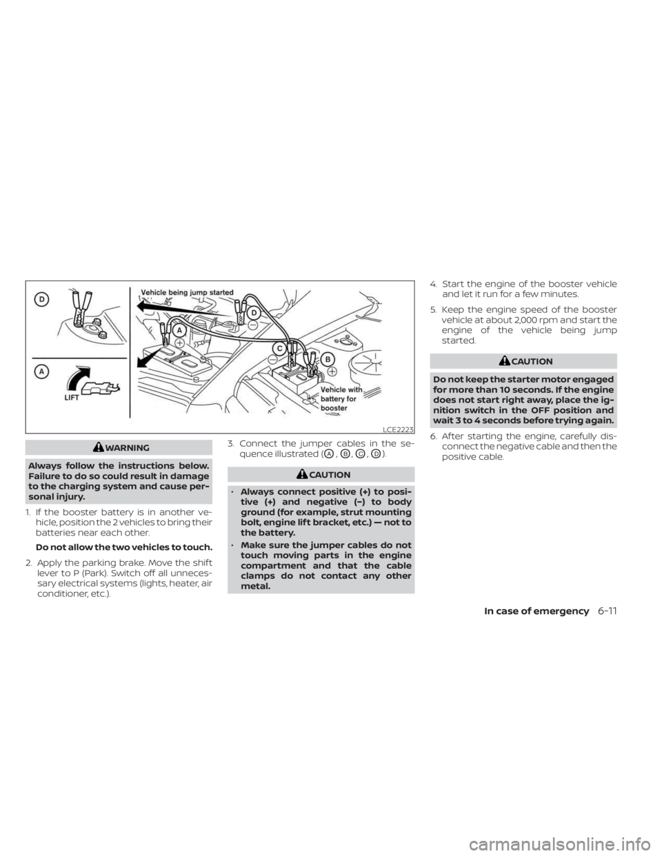
conditioner, etc.). 3. Connect the jumper cables in the se-
quence illustrated (OA,OB,OC,OD).
CAUTION
• Always connect positive (+) to posi-
tive (+) and negative (−) to body
ground (for example, strut mounting
bolt, engine lif t bracket, etc.) — not to
the battery.
• Make sure the jumper cables do not
touch moving parts in the engine
compartment and that the cable
clamps do not contact any other
metal. 4. Start the engine of the booster vehicle
and let it run for a few minutes.
5. Keep the engine speed of the booster vehicle at about 2,000 rpm and start the
engine of the vehicle being jump
started.
CAUTION
Do not keep the starter motor engaged
for more than 10 seconds. If the engine
does not start right away, place the ig-
nition switch in the OFF position and
wait 3 to 4 seconds before trying again.
6. Af ter starting the engine, carefully dis- connect the negative cable and then the
positive cable.
LCE2223
In case of emergency6-11
Page 463 of 558
CAUTION
• Do not ground accessories directly to
the battery terminal. Doing so will
bypass the variable voltage control
system and the vehicle battery may
not charge completely.
• Use electrical accessories with the
engine running to avoid discharging
the vehicle battery. Your vehicle is equipped with a variable
voltage control system. This system mea-
sures the amount of electrical discharge
from the battery and controls voltage gen-
erated by the generator.
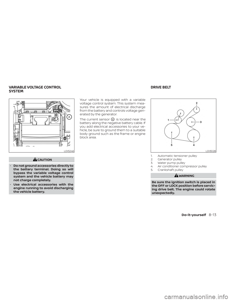
The current sensor
OAis located near the
battery along the negative battery cable. If
you add electrical accessories to your ve-
hicle, be sure to ground them to a suitable
body ground such as the frame or engine
block area.
1. Automatic tensioner pulley
2. Generator pulley
3. Water pump pulley
4. Air conditioner compressor pulley
5. Crankshaf t pulley
WARNING
Be sure the ignition switch is placed in
the OFF or LOCK position before servic-
ing drive belt. The engine could rotate
unexpectedly.
LDI3246LDI3028
VARIABLE VOLTAGE CONTROL
SYSTEM DRIVE BELT
Do-it-yourself8-13
Page 553 of 558
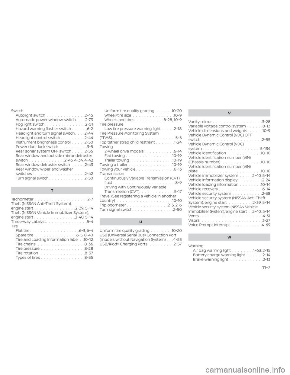
SwitchAutolight switch..............2-45Automatic power window switch. . . .2-73Fog light switch...............2-51Hazard warning flasher switch......6-2Headlight and turn signal switch. . . .2-44Headlight control switch.........2-44Instrument brightness control.....2-50Power door lock switch..........3-5Rear sonar system OFF switch.....2-56Rear window and outside mirror defroster
switch.............2-43, 4-34, 4-42Rear window defroster switch.....2-43Rear window wiper and washer
switches.................. .2-42Turn signal switch.............2-50
T
Tachometer...................2-7Thef t (NISSAN Anti-Thef t System),
engine start...............2-39, 5-14Thef t (NISSAN Vehicle Immobilizer System),
engine start...............2-40, 5-14Three-way catalyst...............5-4Tire
Flat tire................. .6-3, 6-4Spare tire...............6-5, 8-40Tire and Loading Information label. .10-12Tire chains.................8-36Tire pressure................8-28Tire rotation.................8-37Types of tires................8-35
Uniform tire quality grading......10-20Wheel/tire size...............10-9Wheels and tires..........8-28,10-9Tire pressure
Low tire pressure warning light.....2-18Tire Pressure Monitoring System
(TPMS)...................... .5-5Top tether strap child restraint.......1-24Towing
2-wheel drive models...........6-14Flat towing................ .10-19Trailer towing...............10-19Towing a trailer................10-19Towing your vehicle..............6-13Transmission
Continuously Variable Transmission (CVT)
fluid
..................... .8-9Driving with Continuously Variable
Transmission (CVT).............5-17Travel (See registering a vehicle in another
country)....................10-10Trip odometer...............2-5, 2-6Turn signal switch...............2-50
U
Uniform tire quality grading........10-20USB (Universal Serial Bus) Connection Port
(models without Navigation System). . .4-53USB/iPod® Charging Ports.........2-57
V
Vanity mirror..................3-28Variable voltage control system......8-13Vehicle dimensions and weights......10-9Vehicle Dynamic Control (VDC) OFF
switch..................... .2-55Vehicle Dynamic Control (VDC)
system.....................5-134Vehicle identification............10-10Vehicle identification number (VIN)
(Chassis number)..............10-10Vehicle identification number (VIN)
plate......................10-10Vehicle immobilizer system.....2-40, 5-14Vehicle information display.........2-24Vehicle loading information........10-14Vehicle recovery................6-14Vehicle security system...........2-38Vehicle security system (NISSAN Anti-Thef t
System), engine start.........2-39, 5-14Vehicle security system (NISSAN Vehicle
Immobilizer System), engine start. .2-40, 5-14Vents...................... .4-31Visors......................3-27Voice Prompt Interrupt...........4-69
W
Warning
Air bag warning light........1-63, 2-15Battery charge warning light......2-14Brake warning light............2-13
11-7