Page 325 of 604

WARNING
Do not operate the push-button
ignition switch while driving the ve-
hicle except in an emergency. (The
engine will stop when the ignition
switch is pushed 3 consecutive times
or the ignition switch is pushed and
held for more than 2 seconds.) If the
engine stops while the vehicle is
being driven, this could lead to a
crash and serious injury.
Before operating the push-button igni-
tion switch, be sure to move the shift
lever to the P (Park) position.
SSD0436
OPERATING RANGE FOR ENGINE
START FUNCTION
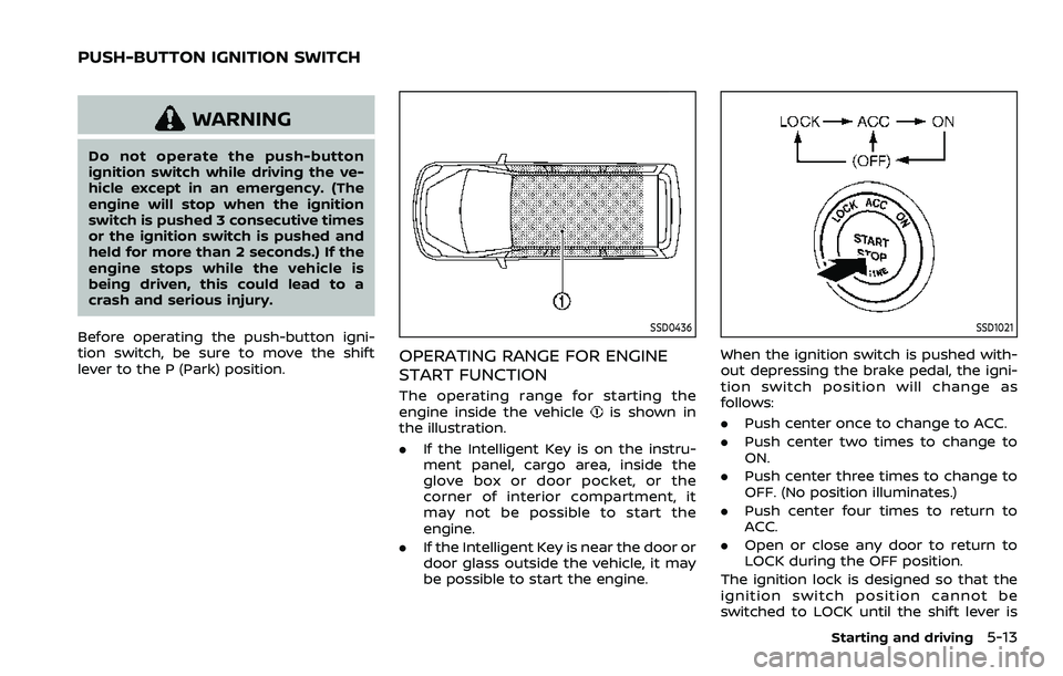
The operating range for starting the
engine inside the vehicleis shown in
the illustration.
. If the Intelligent Key is on the instru-
ment panel, cargo area, inside the
glove box or door pocket, or the
corner of interior compartment, it
may not be possible to start the
engine.
. If the Intelligent Key is near the door or
door glass outside the vehicle, it may
be possible to start the engine.
SSD1021
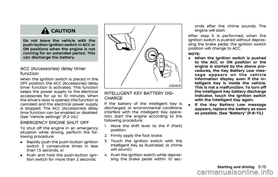
When the ignition switch is pushed with-
out depressing the brake pedal, the igni-
tion switch position will change as
follows:
.Push center once to change to ACC.
. Push center two times to change to
ON.
. Push center three times to change to
OFF. (No position illuminates.)
. Push center four times to return to
ACC.
. Open or close any door to return to
LOCK during the OFF position.
The ignition lock is designed so that the
ignition switch position cannot be
switched to LOCK until the shift lever is
Starting and driving5-13
PUSH-BUTTON IGNITION SWITCH
Page 327 of 604

CAUTION
Do not leave the vehicle with the
push-button ignition switch in ACC or
ON positions when the engine is not
running for an extended period. This
can discharge the battery.
ACC (Accessories) delay timer
function
When the ignition switch is placed in the
OFF position, the ACC (Accessories) delay
timer function is activated. This function
keeps the power supply to the electrical
accessories for up to 10 minutes. When
the driver’s door is opened, this function is
canceled and the electrical power supply
is stopped. The ACC (Accessories) delay
time function can be enabled or disabled.
(See “Vehicle settings” (P.2-24).)
EMERGENCY ENGINE SHUT OFF
To shut off the engine in an emergency
situation while driving, perform the fol-
lowing procedure:
.Rapidly push the push-button ignition
switch 3 consecutive times in less
than 1.5 seconds, or
. Push and hold the push-button igni-
tion switch for more than 2 seconds.
JVS0404X
INTELLIGENT KEY BATTERY DIS-
CHARGE
If the battery of the Intelligent Key is
discharged, or environmental conditions
interfere with the Intelligent Key opera-
tion, start the engine according to the
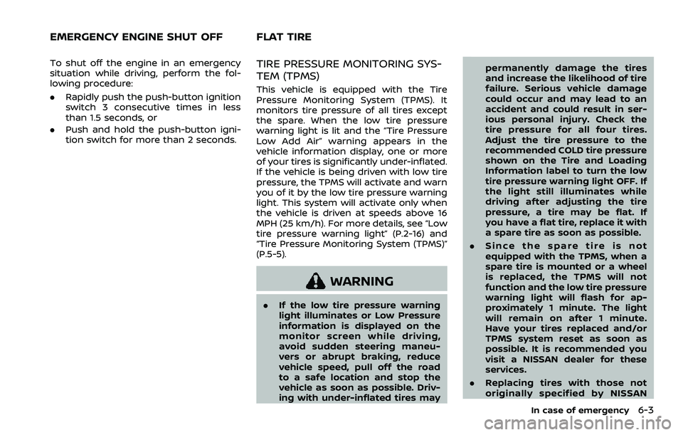
following procedure:
1. Move the shift lever to the P (Park)
position.
2. Firmly apply the foot brake.
3. Touch the ignition switch with the Intelligent Key as illustrated. (A chime
will sound.)
4. Push the ignition switch while depres- sing the brake pedal within 10 sec- onds after the chime sounds. The
engine will start.
After step 3 is performed, when the
ignition switch is pushed without depres-
sing the brake pedal, the ignition switch
position will change to ACC.
NOTE:
. When the ignition switch is pushed
to the ACC or ON position or the
engine is started by the above pro-
cedures, the Key Battery Low mes-
sage appears on the vehicle
information display even if the In-
telligent Key is inside the vehicle.
This is not a malfunction. To turn off
the Intelligent Key battery discharge
indicator, touch the ignition switch
with the Intelligent Key again.
. If the Key Battery Low message
appears, replace the battery as soon
as possible. (See “Battery” (P.8-11).)
Starting and driving5-15
Page 463 of 604

To shut off the engine in an emergency
situation while driving, perform the fol-
lowing procedure:
.Rapidly push the push-button ignition
switch 3 consecutive times in less
than 1.5 seconds, or
. Push and hold the push-button igni-
tion switch for more than 2 seconds.TIRE PRESSURE MONITORING SYS-
TEM (TPMS)
This vehicle is equipped with the Tire
Pressure Monitoring System (TPMS). It
monitors tire pressure of all tires except
the spare. When the low tire pressure
warning light is lit and the “Tire Pressure
Low Add Air” warning appears in the
vehicle information display, one or more
of your tires is significantly under-inflated.
If the vehicle is being driven with low tire
pressure, the TPMS will activate and warn
you of it by the low tire pressure warning
light. This system will activate only when
the vehicle is driven at speeds above 16
MPH (25 km/h). For more details, see “Low
tire pressure warning light” (P.2-16) and
“Tire Pressure Monitoring System (TPMS)”
(P.5-5).
WARNING
.If the low tire pressure warning
light illuminates or Low Pressure
information is displayed on the
monitor screen while driving,
avoid sudden steering maneu-
vers or abrupt braking, reduce
vehicle speed, pull off the road
to a safe location and stop the
vehicle as soon as possible. Driv-
ing with under-inflated tires may permanently damage the tires
and increase the likelihood of tire
failure. Serious vehicle damage
could occur and may lead to an
accident and could result in ser-
ious personal injury. Check the
tire pressure for all four tires.
Adjust the tire pressure to the
recommended COLD tire pressure
shown on the Tire and Loading
Information label to turn the low
tire pressure warning light OFF. If
the light still illuminates while
driving after adjusting the tire
pressure, a tire may be flat. If
you have a flat tire, replace it with
a spare tire as soon as possible.
. Since the spare tire is not
equipped with the TPMS, when a
spare tire is mounted or a wheel
is replaced, the TPMS will not
function and the low tire pressure
warning light will flash for ap-
proximately 1 minute. The light
will remain on after 1 minute.
Have your tires replaced and/or
TPMS system reset as soon as
possible. It is recommended you
visit a NISSAN dealer for these
services.
. Replacing tires with those not
originally specified by NISSAN
In case of emergency6-3
EMERGENCY ENGINE SHUT OFF FLAT TIRE
Page 464 of 604

6-4In case of emergency
could affect the proper operation
of the TPMS.
. Do not inject any tire liquid or
aerosol tire sealant into the tires,
as this may cause a malfunction
of the tire pressure sensors.
CHANGING A FLAT TIRE
If you have a flat tire, follow the instruc-
tions below.
Stopping the vehicle
1. Safely move the vehicle off the road
and away from traffic.
2. Turn on the hazard warning flashers.
3. Park on a level surface and apply the parking brake. Move the shift lever to
the P (Park) position.
4. Turn off the engine.
5. Raise the hood to warn other traffic, and to signal professional road assis-
tance personnel that you need assis-
tance.
6. Have all passengers get out of the vehicle and stand in a safe place, away
from traffic and clear of the vehicle.
WARNING
.Make sure the parking brake is
securely applied and the auto-
matic transmission is in the P
(Park) position.
. Never change tires when the ve-
hicle is on a slope, ice or slippery
areas. This is hazardous.
. Never change tires if oncoming
traffic is close to your vehicle.
Wait for professional road assis-
tance.
MCE0001A
Blocking wheels
Place suitable blocksat both the front
and back of the wheel diagonally oppo-
site the flat tire to prevent the vehicle
from moving when it is jacked up.
WARNING
Be sure to block the wheel as the
vehicle may move and result in
personal injury.
Page 466 of 604
6-6In case of emergency
JVE0423X
5. Securely screw to connect the T-shaped end of the jack rod and the
extension bar
as illustrated.
6. Fit the square end of the jack rod into the square hole of the wheel nut
wrench to form a handle
. 7. Locate the oval opening above the
middle of the rear bumper.
8. Place the T-shaped end of the jack rod through the opening and direct it
towards the spare wheel winch as-
sembly, located directly above the
spare wheel.
SCE0916
CAUTION
Do not insert the jack rod straight as
it is designed to be inserted at an
angle as shown.
9. Seat the T-shaped end of the jack rod into the T-shaped opening of the
spare wheel winch. Apply pressure to
keep the jack rod engaged in the
spare wheel winch and turn the jack
rod counterclockwise to lower the
spare wheel.
Page 467 of 604
SCE0377
10. Once the spare wheel is completelylowered, remove the jack rod and
reach under the vehicle to remove
the hanging plate.
11. Carefully slide the spare wheel from under the rear of the vehicle.
After preparing the spare tire, to remove
the rod, pull out the rod while moving the
rod to the right and left with the screw of
the extension facing the side.
CAUTION
When storing the wheel, make sure
that the hanging plate is in the center of the wheel and then lift it
up into the storage area.
WAG0102X
CAUTION
When storing the wheel, be sure to
mount the wheel horizontally. Secur-
ing the wheel that is in a tilted
position as illustrated may cause
In case of emergency6-7
Page 469 of 604
SCE0876
2. Loosen each wheel nut one or twoturns by turning counterclockwise
with the wheel nut wrench. Do not
remove the wheel nuts until the tire
is off the ground.
NCE130
3. Install the assembled jack rod into the
jack as shown.
4. Carefully raise the vehicle until the clearance between the tire and
ground is achieved.
5. To lift the vehicle, securely hold the jack lever and rod with both hands
and turn the jack lever.
NOTE:
Before jacking up the vehicle, make
sure the ignition switch is placed in
the OFF position. If the vehicle is lifted
up with the engine running, the auto-
leveling suspension will become dis-
abled after 120 seconds. To reset the
auto-leveling suspension, cycle the
In case of emergency6-9
Page 470 of 604

6-10In case of emergency
ignition switch ON/OFF one time.
SCE0910
Installing the spare tire
The full-size temporary use only spare
tire (if so equipped) is designed for
emergency use. (See specific instruc-
tions under the heading “Wheels and
tires” (P.8-28).)
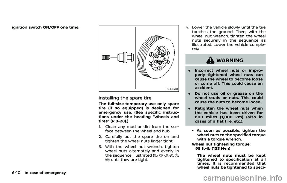
1. Clean any mud or dirt from the sur-face between the wheel and hub.
2. Carefully put the spare tire on and tighten the wheel nuts finger tight.
3. With the wheel nut wrench, tighten wheel nuts alternately and evenly in
the sequence illustrated (
,,,,,) until they are tight. 4. Lower the vehicle slowly until the tire
touches the ground. Then, with the
wheel nut wrench, tighten the wheel
nuts securely in the sequence as
illustrated. Lower the vehicle comple-
tely.
WARNING
.Incorrect wheel nuts or impro-
perly tightened wheel nuts can
cause the wheel to become loose
or come off. This could cause an
accident.
. Do not use oil or grease on the
wheel studs or nuts. This could
cause the nuts to become loose.
. Retighten the wheel nuts when
the vehicle has been driven for
600 miles (1,000 km) (also in
cases of a flat tire, etc.).
.As soon as possible, tighten the
wheel nuts to the specified torque
with a torque wrench.
Wheel nut tightening torque: 98 ft-lb (133 N·m)
The wheel nuts must be kept
tightened to specification at all
times. It is recommended that
wheel nuts be tightened to speci-