2023 NISSAN ALTIMA air condition
[x] Cancel search: air conditionPage 122 of 644
and malfunction warning (red) will illumi-
nate. Have the system checked. It is recom-
mended that you visit a NISSAN dealer im-
mediately for this service.
Engine Stalled: Stop safely
This message appears 30 seconds before
the vehicle is shut down due to an above
normal operating exhaust temperature.
The Malfunction Indicator Light (MIL) and
malfunction warning (red) will illuminate.
Have the system checked. It is recom-
mended that you visit a NISSAN dealer im-
mediately for this service.
Engine Malfunction Power reduced
Service now
This warning appears when the engine is
not operating under normal conditions. If
this warning appears, have the system
checked. It is recommended that you visit a
NISSAN dealer for this service.
Engine Malfunction Service now
This warning appears when there is a
problem with the engine. If this warning
appears, have the system checked. It is rec-
ommended that you visit a NISSAN dealer
for this service.
Engine hot Power reduced
This engine has a high fluid temperature
protection mode. If the fluid temperature
becomes too high (for example, climbing
steep grades in high temperatures with
heavy loads, such as when towing a trailer),
engine power and, under some conditions,
vehicle speed will be decreased automati-
cally to reduce the chance of engine dam-
age. Vehicle speed can be controlled with
the accelerator pedal, but the engine and
vehicle speed may be reduced.
WARNING
When the high fluid temperature pro-
tection mode operation occurs, vehicle
speed may be gradually reduced. The
reduced speed may be lower than
other traffic, which could increase the
chance of a collision. Be especially
careful when driving. If necessary, pull
to the side of the road at a safe place
and allow the engine to return to nor-
mal operation; or have it repaired if
necessary.
Automatic Emergency
Braking (AEB) with
Pedestrian Detection
emergency warning
indicator
This indicator appears along, with an au-
dible warning, when the system detects
the possibility of a forward collision.
For additional information, see “Automatic
Emergency Braking (AEB) with Pedestrian
Detection” (P. 5-135).
Blind Spot Warning (BSW)
indicator
This indicator appears when the BSW sys-
tem is engaged.
For additional information, see “Blind Spot
Warning (BSW)” (P. 5-46).
Cruise control indicator
This indicator shows the cruise control sys-
tem status.
When cruise control is activated, a green
circle will appear to indicate it is set. The
vehicle information display will also display
the speed the cruise control was set at. If
you accelerate past the set speed, the
speed will blink until you either cancel
cruise control or go back to the set speed. If
2-32Instruments and controls
Page 138 of 644
Shipping Mode On Push Storage Fuse
This warning may appear if the extended
storage switch is not pushed in. When this
warning appears, push in the extended
storage switch to turn off the warning. For
additional information, see “Extended stor-
age switch” (P. 2-70).
Timer Alert Time for a
break?
This message appears when the set time
is reached. This time can be set up to six
hours. For additional information, see
“Driver Assistance” (P. 2-38)
Tire Pressure Low - Add Air
This warning appears when the low tire
pressure warning light in the meter illumi-
nates and low tire pressure is detected. The
warning appears each time the ignition
switch is placed in the ON position as long
as the low tire pressure warning light re-
mains illuminated. If this warning appears,
stop the vehicle and adjust the tire pres-
sures of all four tires to the recommended
COLD tire pressure shown on the Tire and
Loading Information label. For additional
information, see “Low tire pressure warning
light” (P. 2-13) and “Tire Pressure Monitoring
System (TPMS)” (P. 5-5).
Transmission Shif t Position
indicator
This indicator shows the transmission shif t
position.
AWD Error: See Owner’s
Manual
This warning appears when the All-Wheel
Drive (AWD) system is not functioning prop-
erly while the engine is running.
AWD High Temp. Stop
Vehicle
This warning may appear while trying to
free a stuck vehicle due to increased oil
temperature. The driving mode may
change to 2-Wheel Drive (2WD). If this
warning is displayed, stop the vehicle with
the engine idling, as soon as it is safe to do
so. Then if the warning turns off, you can
continue driving.
Tire Size Incorrect See
Owner’s Manual
This warning may appear if there is a large
difference between the diameters of the
front and rear wheels. Pull off the road in a
safe area, with the engine idling. Check that
all the tire sizes are the same, that the tirepressure is correct and that the tires are
not excessively worn.
CVT (AT) Malfunction
Service now
This warning appears when there is a
problem with the CVT system. If this
warning appears, have the system
checked. It is recommended that you visit a
NISSAN dealer for this service.
CVT (AT) hot Power reduced
This transmission has a high fluid tem-
perature protection mode. If the fluid tem-
perature becomes too high (for example,
climbing steep grades in high tempera-
tures with heavy loads, such as when tow-
ing a trailer), engine power and, under
some conditions, vehicle speed will be de-
creased automatically to reduce the
chance of transmission damage. Vehicle
speed can be controlled with the accelera-
tor pedal, but the engine and vehicle speed
may be reduced.
2-48Instruments and controls
Page 139 of 644
WARNING
When the high fluid temperature pro-
tection mode operation occurs, vehicle
speed may be gradually reduced. The
reduced speed may be lower than
other traffic, which could increase the
chance of a collision. Be especially
careful when driving. If necessary, pull
to the side of the road at a safe place
and allow the transmission to return to
normal operation; or have it repaired if
necessary.
CVT (AT) Stop the vehicle
This message appears 30 seconds before
the vehicle is shut down due to an above
normal operating transmission tempera-
ture. The Malfunction Indicator Light (MIL)
and malfunction warning (red) will illumi-
nate. Have the system checked. It is recom-
mended that you visit a NISSAN dealer im-
mediately for this service.
Automatic Emergency
Braking (AEB) with
Pedestrian Detection
emergency warning
indicator
This indicator appears along, with an au-
dible warning, when the system detects
the possibility of a forward collision.
For additional information, see “Automatic
Emergency Braking (AEB) with Pedestrian
Detection” (P. 5-135).
Blind Spot Warning (BSW)
indicator
This indicator appears when the BSW sys-
tem is engaged.
For additional information, see “Blind Spot
Warning (BSW)” (P. 5-46).
Cruise control indicator
This indicator shows the cruise control sys-
tem status.
When cruise control is activated, a green
circle will appear to indicate it is set. The
vehicle information display will also display
the speed the cruise control was set at. If
you accelerate past the set speed, the
speed will blink until you either cancel
cruise control or go back to the set speed. If cruise control is on and canceled, the
speed will be displayed to show the speed
the vehicle will return to if the resume but-
ton is activated.
Currently not available
This message may appear when the ProPI-
LOT Assist system or the Intelligent Lane
Intervention (I-LI) system is engaged.
Under the following conditions, the ProPI-
LOT Assist or the Intelligent Lane Interven-
tion (I-LI) system is automatically canceled:
• When the VDC system is turned off
The above system cannot be used in some
situations (VDC operates, wheel slip and
VDC system is off.)
Driver Attention Alert
Malfunction
This warning appears when the Intelligent
Driver Alertness (I-DA) system is not func-
tioning properly. For additional information,
see “Intelligent Driver Alertness (I-DA)”
(P. 5-162).
Driver Attention Alert—
TakeaBreak?
This alert appears when the system has
detected that the driver may be displaying
fatigue or a lack of attention.
Instruments and controls2-49
Page 159 of 644
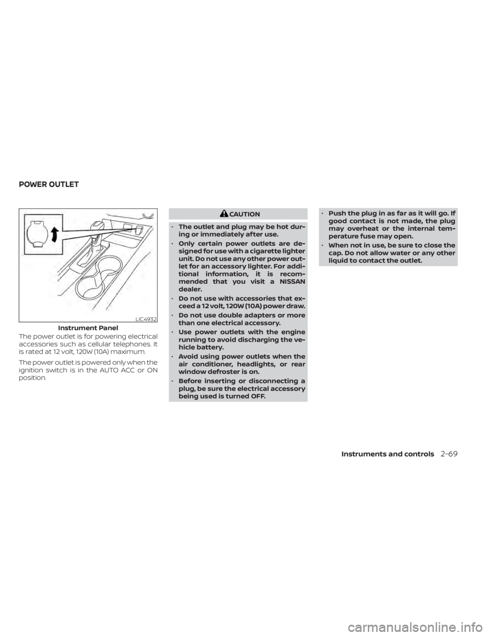
The power outlet is for powering electrical
accessories such as cellular telephones. It
is rated at 12 volt, 120W (10A) maximum.
The power outlet is powered only when the
ignition switch is in the AUTO ACC or ON
position.
CAUTION
• The outlet and plug may be hot dur-
ing or immediately af ter use.
• Only certain power outlets are de-
signed for use with a cigarette lighter
unit. Do not use any other power out-
let for an accessory lighter. For addi-
tional information, it is recom-
mended that you visit a NISSAN
dealer.
• Do not use with accessories that ex-
ceed a 12 volt, 120W (10A) power draw.
• Do not use double adapters or more
than one electrical accessory.
• Use power outlets with the engine
running to avoid discharging the ve-
hicle battery.
• Avoid using power outlets when the
air conditioner, headlights, or rear
window defroster is on.
• Before inserting or disconnecting a
plug, be sure the electrical accessory
being used is turned OFF. •
Push the plug in as far as it will go. If
good contact is not made, the plug
may overheat or the internal tem-
perature fuse may open.
• When not in use, be sure to close the
cap. Do not allow water or any other
liquid to contact the outlet.
LIC4932
Instrument Panel
POWER OUTLET
Instruments and controls2-69
Page 167 of 644
Auto-reverse function
If the control unit detects something
caught in the window as it is closing, the
window will be immediately lowered.
The auto-reverse function can be acti-
vated when the window is closed by auto-
matic operation when the ignition switch is
placed in the ON position or for a period of
time af ter the ignition switch is placed in
the OFF position.
Depending on the environment or driv-
ing conditions, the auto-reverse func-
tion may be activated if an impact or
load similar to something being caught
in the window occurs.
WARNING
There are some small distances imme-
diately before the closed position
which cannot be detected. Make sure
that all passengers have their hands,
etc., inside the vehicle before closing
the window.
When power window switch does
not operate
If the power window automatic function
(closing only) does not operate properly, perform the following procedure to initial-
ize the power window system:
1. Place the ignition switch in the ON
position.
2. Open the window more than half way by operating the power window switch.
3. Pull the power window switch and hold it to close the window, and then hold the
switch more than 3 seconds af ter the
window is closed.
4. Release the power window switch. Op- erate the window by the automatic
function to confirm the initialization is
complete. The power window automati-
cally opens or closes depending on if the
automatic down or up function is
selected.
5. Perform steps 2 through 4 above for other windows.
If the power window function does not op-
erate properly af ter performing the above
procedure have the system checked and
repaired. It is recommended that you visit a
NISSAN dealer for this service.
POWER MOONROOF
The moonroof will only operate when the
ignition switch is placed in the ON position.
The power moonroof is operational for a
period of time, even if the ignition switch is
placed in the AUTO ACC or OFF position. If
the driver's door or the front passenger's
door is opened during this period of time,
the power to the moonroof is canceled.
Sliding the moonroof
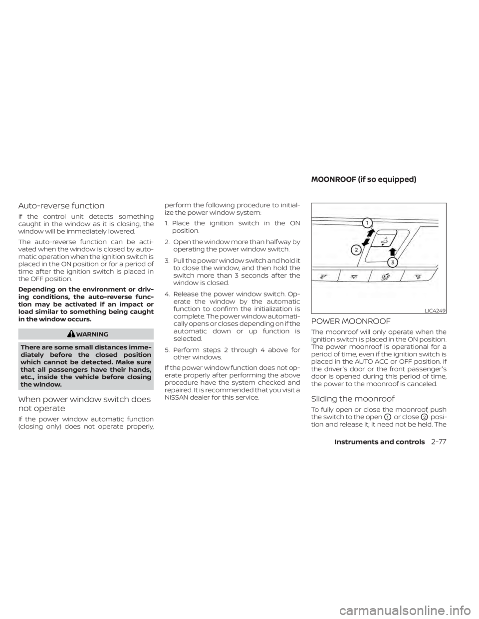
To fully open or close the moonroof, push
the switch to the open
O1or closeO2posi-
tion and release it; it need not be held. The
LIC4249
MOONROOF (if so equipped)
Instruments and controls2-77
Page 183 of 644
CHILD SAFETY REAR DOOR LOCK
Child safety locks help prevent the rear
doors from being opened accidentally, es-
pecially when small children are in the
vehicle.
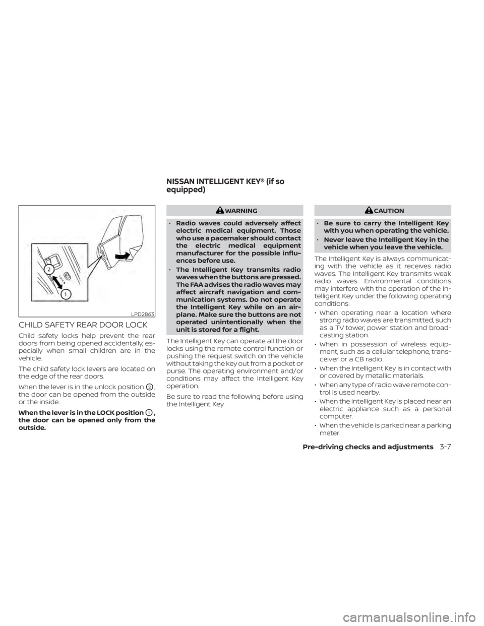
The child safety lock levers are located on
the edge of the rear doors.
When the lever is in the unlock position
O2,
the door can be opened from the outside
or the inside.
When the lever is in the LOCK position
O1,
the door can be opened only from the
outside.
WARNING
• Radio waves could adversely affect
electric medical equipment. Those
who use a pacemaker should contact
the electric medical equipment
manufacturer for the possible influ-
ences before use.
• The Intelligent Key transmits radio
waves when the buttons are pressed.
The FAA advises the radio waves may
affect aircraf t navigation and com-
munication systems. Do not operate
the Intelligent Key while on an air-
plane. Make sure the buttons are not
operated unintentionally when the
unit is stored for a flight.
The Intelligent Key can operate all the door
locks using the remote control function or
pushing the request switch on the vehicle
without taking the key out from a pocket or
purse. The operating environment and/or
conditions may affect the Intelligent Key
operation.
Be sure to read the following before using
the Intelligent Key.CAUTION
• Be sure to carry the Intelligent Key
with you when operating the vehicle.
• Never leave the Intelligent Key in the
vehicle when you leave the vehicle.
The Intelligent Key is always communicat-
ing with the vehicle as it receives radio
waves. The Intelligent Key transmits weak
radio waves. Environmental conditions
may interfere with the operation of the In-
telligent Key under the following operating
conditions:
• When operating near a location where strong radio waves are transmitted, such
as a TV tower, power station and broad-
casting station.
• When in possession of wireless equip- ment, such as a cellular telephone, trans-
ceiver or a CB radio.
• When the Intelligent Key is in contact with or covered by metallic materials.
• When any type of radio wave remote con- trol is used nearby.
• When the Intelligent Key is placed near an electric appliance such as a personal
computer.
• When the vehicle is parked near a parking meter.
LPD2863
NISSAN INTELLIGENT KEY® (if so
equipped)
Pre-driving checks and adjustments3-7
Page 210 of 644
4 Monitor, climate, audio, phone and
voice recognition systems
NissanConnect® Owner’s Manual...............4-2
Control panel buttons ...........................4-3
How to use the touch-screen ................4-4
How to use the
MENU button ...........4-5(brightness control) button .............4-7
How to use the VOL (volume) knob /
PUSH
(power)button....................4-7
Selecting menu from launch bar .............4-7
RearView Monitor (if so equipped) ...............4-8
RearView Monitor system operation ..........4-9
How to read the displayed lines ..............4-9
Difference between predicted and
actual distances ............................ 4-10
How to park with predicted course
lines .......................................... 4-11
Adjusting the screen ........................ 4-13
How to turn on and off predicted
course lines ................................. 4-13
RearView Monitor system limitations ........4-13
System maintenance ....................... 4-15
Intelligent Around View Monitor
(if so equipped) ................................. 4-16
Intelligent Around View Monitor system
operation ................................... 4-17
Difference between predicted and
actual distances ............................ 4-20How to park with predicted course
lines
......................................... 4-22
How to switch the display ...................4-23
Adjusting the screen ........................ 4-24
Intelligent Around View Monitor system
limitations .................................. 4-24
System maintenance .......................4-26
Moving Object Detection (MOD)
(if so equipped) ................................. 4-27
MOD system operation ......................4-28
Turning MOD on and off (if so equipped) .....4-30
MOD system limitations .....................4-30
System maintenance ....................... 4-31
Vents .......................................... 4-31
Heater and air conditioner (manual)
(if so equipped) ................................. 4-33
Controls ..................................... 4-34
Heater operation ............................ 4-34
Air conditioner operation ....................4-35
Air flow charts ............................... 4-36
Heater and air conditioner (automatic)
(if so equipped) ................................. 4-40
Automatic operation ........................ 4-41
Manual operation ........................... 4-42
Operating tips ............................... 4-43
Page 211 of 644
Servicing air conditioner........................4-44
Audio system .................................. 4-45
Radio ....................................... 4-45
FM radio reception .......................... 4-45
AM radio reception .......................... 4-45
Audio operation precautions ................4-46
FM/AM radio ................................ 4-49
USB (Universal Serial Bus) Connection
Port......................................... 4-54
iPod®* player operation .....................4-57
Bluetooth® streaming audio .................4-60
Steering wheel switch for audio control .....4-63
Antenna ........................................ 4-64
Siri® Eyes Free (if so equipped) ..................4-64
Requirements ............................... 4-64
Operating Siri® Eyes Free ....................4-65
Troubleshooting guide ......................4-66Car phone or CB radio
.......................... 4-67
Bluetooth® Hands-Free Phone System .........4-67
Regulatory information ......................4-69
Using the system ........................... 4-69
Indicators ................................... 4-71
Control buttons ............................. 4-71
Bluetooth® connecting procedure ...........4-72
Voice commands ........................... 4-73
Phone display screen .......................4-75
Making a call ................................ 4-76
Receiving/Ending a call ......................4-76
During a call ................................. 4-77
Text messaging (if so equipped) .............4-77
Bluetooth® connections screen .............4-81
Phone and text message settings ...........4-82
Volume & beeps ............................. 4-84
iPod®/iPhone® ................................. 4-84