2023 NISSAN ALTIMA air condition
[x] Cancel search: air conditionPage 463 of 644
CAUTION
During the first 1,200 miles (2,000 km),
follow these recommendations to ob-
tain maximum engine performance
and ensure the future reliability and
economy of your new vehicle. Failure to
follow these recommendations may
result in shortened engine life and re-
duced engine performance.
• Avoid driving for long periods at constant speed, either fast or slow, and do not run
the engine over 4,000 rpm.
• Do not accelerate at full throttle in any gear.
• Avoid quick starts.
• Avoid hard braking as much as possible. Follow these easy-to-use Fuel Efficient
Driving Tips to help you achieve the most
fuel economy from your vehicle.
1.
Use Smooth Accelerator and Brake
Pedal Application
• Avoid rapid starts and stops.
• Use smooth, gentle accelerator and brake application whenever possible.
• Maintain constant speed while com- muting and coast whenever possible.
2. Maintain Constant Speed
• Look ahead to try and anticipate and minimize stops.
• Synchronizing your speed with traffic lights allows you to reduce your num-
ber of stops.
• Maintaining a steady speed can mini- mize red light stops and improve fuel
efficiency.
3. Use Air Conditioning (A/C) at Higher
Vehicle Speeds
• Below 40 mph (64 km/h), it is more efficient to open windows to cool the
vehicle due to reduced engine load.
• Above 40 mph (64 km/h), it is more efficient to use A/C to cool the vehicle
due to increased aerodynamic drag. • Recirculating the cool air in the cabin
when the A/C is on reduces cooling
load.
4. Drive at Economical Speeds and
Distances
• Observing the speed limit and not ex- ceeding 60 mph (97 km/h) (where le-
gally allowed) can improve fuel effi-
ciency due to reduced aerodynamic
drag.
• Maintaining a safe following distance behind other vehicles reduces unnec-
essary braking.
• Safely monitoring traffic to anticipate changes in speed permits reduced
braking and smooth acceleration
changes.
• Select a gear range suitable to road conditions.
5. Use Cruise Control
• Using cruise control during highway driving helps maintain a steady speed.
• Cruise control is particularly effective in providing fuel savings when driving
on flat terrains.
6. Plan for the Shortest Route
• Utilize a map or navigation system to determine the best route to save time.
BREAK-IN SCHEDULE FUEL EFFICIENT DRIVING TIPS
Starting and driving5-167
Page 475 of 644
When the vehicle is stopped on a hill, the hill
start assist system automatically keeps
the brakes applied to help prevent the ve-
hicle from rolling backward in the time it
takes the driver to release the brake pedal
and apply the accelerator.
The hill start assist system will operate au-
tomatically under the following conditions:
• The transmission is shif ted to a forwardor reverse gear.
• The vehicle is stopped completely on a hill by applying the brake. The maximum
holding time is 2 seconds. Af ter 2 sec-
onds the vehicle will begin to roll back and
the hill start assist system will stop oper-
ating completely.
The hill start assist system will not operate
when the shif t lever is placed in the N (Neu-
tral) or P (Park) position or on a flat and level
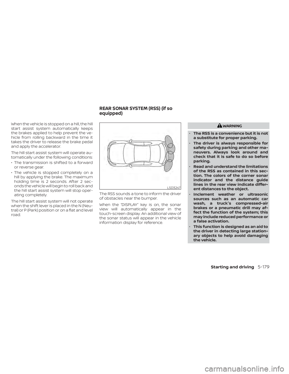
road. The RSS sounds a tone to inform the driver
of obstacles near the bumper.
When the “DISPLAY” key is on, the sonar
view will automatically appear in the
touch-screen display. An additional view of
the sonar status will appear in the vehicle
information display for reference.WARNING
• The RSS is a convenience but it is not
a substitute for proper parking.
• The driver is always responsible for
safety during parking and other ma-
neuvers. Always look around and
check that it is safe to do so before
parking.
• Read and understand the limitations
of the RSS as contained in this sec-
tion. The colors of the corner sonar
indicator and the distance guide
lines in the rear view indicate differ-
ent distances to the object.
• Inclement weather or ultrasonic
sources such as an automatic car
wash, a truck's compressed-air
brakes or a pneumatic drill may af-
fect the function of the system; this
may include reduced performance or
a false activation.
• This function is designed as an aid to
the driver in detecting large station-
ary objects to help avoid damaging
the vehicle.
LSD3247
REAR SONAR SYSTEM (RSS) (if so
equipped)
Starting and driving5-179
Page 480 of 644
SONAR LIMITATIONS
WARNING
Listed below are the system limitations
for the sonar system. Failure to operate
the vehicle in accordance with these
system limitations could result in seri-
ous injury or death.
• The system is deactivated at speeds
above 6 mph (10 km/h). It is reacti-
vated at lower speeds.
• Inclement weather or ultrasonic
sources such as an automatic car
wash, a truck’s compressed-air
brakes or a pneumatic drill may af-
fect the function of the system; this
may include reduced performance or
a false activation.
• The system is not designed to pre-
vent contact with small or moving
objects. Always move slowly. The
system will not detect small objects
below the bumper or on the ground.
• The system may not detect the fol-
lowing objects: fluff y objects such as
snow, cloth, cotton, glass-wool, etc.;
thin objects such as rope, wire and
chain, etc.; or wedge-shaped objects. •
The system may not detect objects
at speeds above 3 mph (5 km/h) and
may not detect certain angular or
moving objects.
• Do not attach stickers (including
transparent material), install acces-
sories, or apply anything blocking
the sensors. These conditions may
reduce the ability of the system.
SYSTEM TEMPORARILY
UNAVAILABLE
When sonar blockage is detected, the sys-
tem will be deactivated automatically.
The system is not available until the condi-
tions no longer exist.
The sonar sensors may be blocked by tem-
porary ambient conditions such as splash-
ing water, mist or fog. The blocked condi-
tion may also be caused by objects such as
ice, frost or dirt obstructing the sonar
sensors.
Action to take:
When the above conditions no longer exist,
the system will resume automatically.
SYSTEM MAINTENANCE
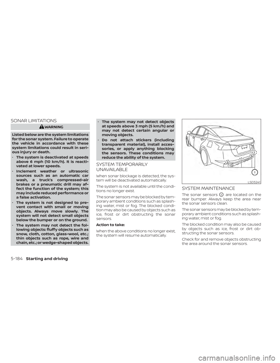
The sonar sensorsO1are located on the
rear bumper. Always keep the area near
the sonar sensors clean.
The sonar sensors may be blocked by tem-
porary ambient conditions such as splash-
ing water, mist or fog.
The blocked condition may also be caused
by objects such as ice, frost or dirt ob-
structing the sonar sensors.
Check for and remove objects obstructing
the area around the sonar sensors.
LSD3241
5-184Starting and driving
Page 496 of 644
–Only use the kit to inflate the tires
of your vehicle and to check the
vehicle’s tire pressure.
– Only plug the compressor into a
12-volt DC car power point.
– Keep the kit free of water and dirt.
– Do not disassemble or modif y the
kit.
– Do not drop the kit or allow hard
impacts to the kit.
• Do not use the emergency tire punc-
ture repair kit under the following
conditions. It is recommended that
you visit a NISSAN dealer or profes-
sional road assistance.
– when the sealant has passed its
expiration date (shown on the la-
bel attached to the bottle)
– when the cut or the puncture is
approximately 0.25 in (6 mm) or
longer
– when the tire sidewall is damaged
– when the vehicle has been driven
with extremely low tire pressure
– when the tire has come off the in-
side or the outside of the wheel
– when the tire wheel is damaged
– when two or more tires are flat If you have a flat tire, follow the instructions
below.
Stopping the vehicle
1. Safely move the vehicle off the road and
away from traffic.
2. Turn on the hazard warning flashers.
3. Park on a level surface and apply the parking brake.
4. Move the shif t lever to the P (Park) position.
5. Turn off the engine.
6. Raise the hood to warn other traffic and to signal professional road assistance
personnel that you need assistance.
7. Have all passengers get out of the ve- hicle and stand in a safe place, away
from traffic and clear of the vehicle.
WARNING
• Make sure the parking brake is se-
curely applied and the vehicle is
placed into the P (Park) position.
• Never repair tires when the vehicle is
on a slope, ice or slippery areas. This
is hazardous.
• Never repair tires if oncoming traffic
is close to your vehicle. Wait for pro-
fessional road assistance.
6-12In case of emergency
Page 502 of 644
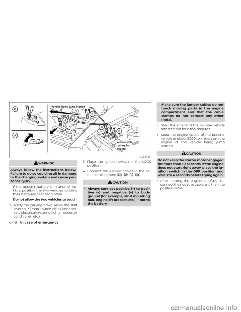
WARNING
Always follow the instructions below.
Failure to do so could result in damage
to the charging system and cause per-
sonal injury.
1. If the booster battery is in another ve- hicle, position the two vehicles to bring
their batteries near each other.
Do not allow the two vehicles to touch.
2. Apply the parking brake. Move the shif t lever to P (Park). Switch off all unneces-
sary electrical systems (lights, heater, air
conditioner, etc.). 3. Place the ignition switch in the LOCK
position.
4. Connect the jumper cables in the se- quence illustrated (
OA,OB,OC,OD).
CAUTION
• Always connect positive (+) to posi-
tive (+) and negative (−) to body
ground (for example, strut mounting
bolt, engine lif t bracket, etc.) — not to
the battery. •
Make sure the jumper cables do not
touch moving parts in the engine
compartment and that the cable
clamps do not contact any other
metal.
5. Start the engine of the booster vehicle and let it run for a few minutes.
6. Keep the engine speed of the booster vehicle at about 2,000 rpm and start the
engine of the vehicle being jump
started.
CAUTION
Do not keep the starter motor engaged
for more than 10 seconds. If the engine
does not start right away, place the ig-
nition switch in the OFF position and
wait 3 to 4 seconds before trying again.
7. Af ter starting the engine, carefully dis- connect the negative cable and then the
positive cable.LCE2223
6-18In case of emergency
Page 503 of 644
CAUTION
• Do not push start this vehicle. The
three-way catalyst may be
damaged.
• Continuously Variable Transmission
(CVT) models cannot be push-
started or tow-started. Attempting
to do so may cause transmission
damage. If your vehicle is overheating (indicated by
an extremely high temperature gauge
reading), or if you feel a lack of engine
power, detect abnormal noise, etc. take the
following steps.
WARNING
• Do not continue to drive if your ve-
hicle overheats. Doing so could cause
engine damage or a vehicle fire.
• To avoid the danger of being scalded,
never remove the radiator or coolant
reservoir cap while the engine is still
hot. When the radiator or coolant res-
ervoir cap is removed, pressurized
hot water will spurt out, possibly
causing serious injury.
• Do not open the hood if steam is
coming out.
1. Move the vehicle safely off the road, ap- ply the parking brake and move the shif t
lever to P (Park).
Do not stop the engine.
2. Turn off the air conditioner. Open all the windows, move the heater or air condi-
tioner temperature control to maximum
hot and fan control to high speed. 3. Get out of the vehicle. Look and listen for
steam or coolant escaping from the ra-
diator before opening the hood. (If
steam or coolant is escaping, turn off
the engine.) Do not open the hood fur-
ther until no steam or coolant can be
seen.
4. Open the engine hood.
WARNING
If steam or water is coming from the
engine, stand clear to prevent getting
burned.
5. Visually check drive belts for damage or looseness. Also check if the cooling fan
is running. The radiator hoses and radia-
tor should not leak water. If coolant is
leaking, the water pump belt is missing
or loose, or the cooling fan does not run,
stop the engine.
WARNING
Be careful not to allow your hands, hair,
jewelry or clothing to come into con-
tact with, or get caught in, engine belts
or the engine cooling fan. The engine
cooling fan can start at any time.
PUSH STARTING IF YOUR VEHICLE OVERHEATS
In case of emergency6-19
Page 532 of 644
CAUTION
• Do not ground accessories directly to
the battery terminal. Doing so will
bypass the variable voltage control
system and the vehicle battery may
not charge completely.
• Use electrical accessories with the
engine running to avoid discharging
the vehicle battery. Your vehicle is equipped with a variable
voltage control system. This system mea-
sures the amount of electrical discharge
from the battery and controls voltage gen-
erated by the generator.
The current sensor is located near the bat-
tery along the negative battery cable. If you
add electrical accessories to your vehicle,
be sure to ground them to a suitable body
ground such as the frame or engine block
area.
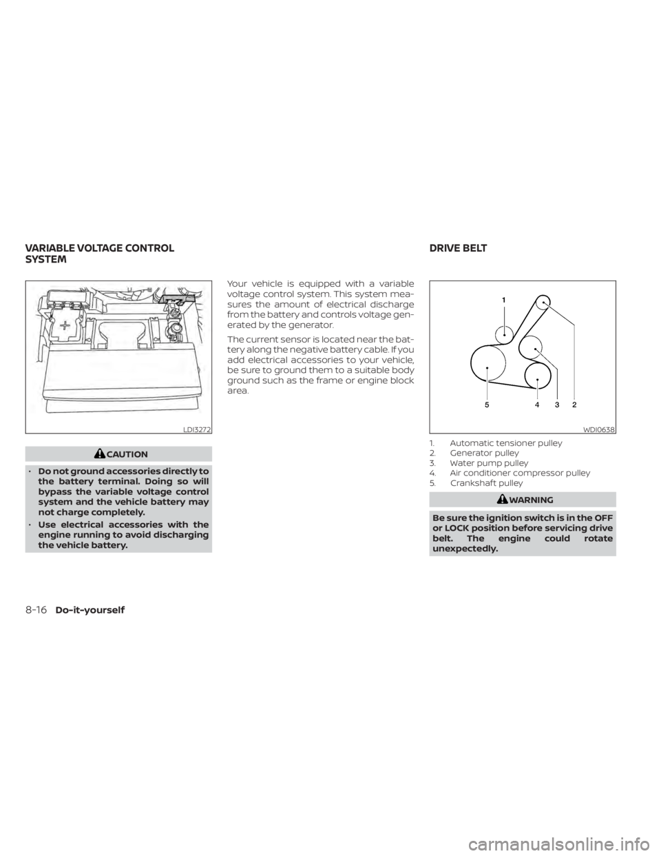
1. Automatic tensioner pulley
2. Generator pulley
3. Water pump pulley
4. Air conditioner compressor pulley
5. Crankshaf t pulley
WARNING
Be sure the ignition switch is in the OFF
or LOCK position before servicing drive
belt. The engine could rotate
unexpectedly.
LDI3272WDI0638
VARIABLE VOLTAGE CONTROL
SYSTEM DRIVE BELT
8-16Do-it-yourself
Page 538 of 644
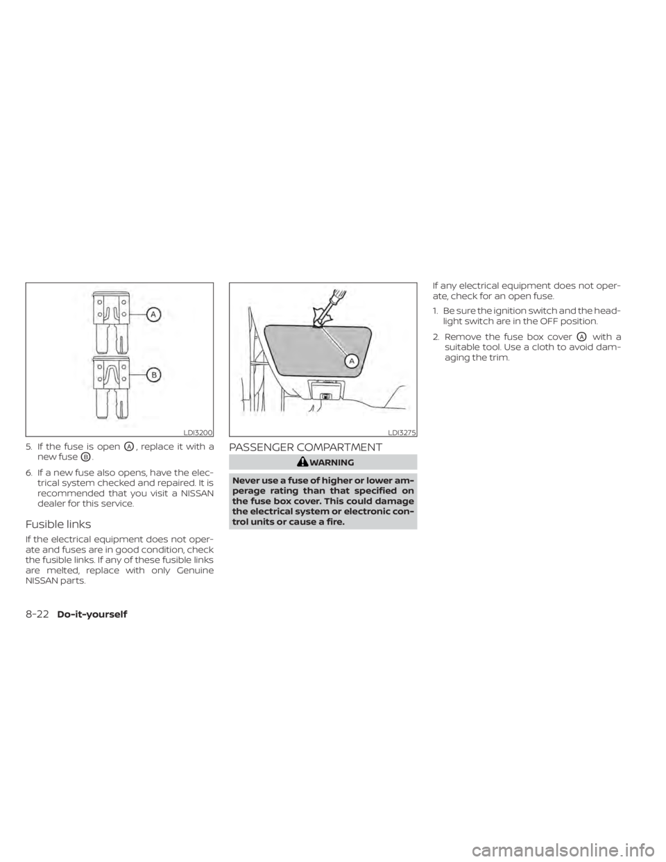
5. If the fuse is openOA, replace it with a
new fuse
OB.
6. If a new fuse also opens, have the elec- trical system checked and repaired. It is
recommended that you visit a NISSAN
dealer for this service.
Fusible links
If the electrical equipment does not oper-
ate and fuses are in good condition, check
the fusible links. If any of these fusible links
are melted, replace with only Genuine
NISSAN parts.
PASSENGER COMPARTMENT
WARNING
Never use a fuse of higher or lower am-
perage rating than that specified on
the fuse box cover. This could damage
the electrical system or electronic con-
trol units or cause a fire. If any electrical equipment does not oper-
ate, check for an open fuse.
1. Be sure the ignition switch and the head-
light switch are in the OFF position.
2. Remove the fuse box cover
OAwith a
suitable tool. Use a cloth to avoid dam-
aging the trim.
LDI3200LDI3275
8-22Do-it-yourself