Page 49 of 276

GETTING TO KNOW YOUR VEHICLE47
Driver And Passenger Temperature Up And
Down Buttons
These buttons provide the driver and
passenger with independent temperature
control.
Push the red button on the faceplate or
touchscreen or press and slide the
temperature bar towards the red arrow button
on the touchscreen for warmer temperature
settings.
Push the blue button on the faceplate or
touchscreen or press and slide the
temperature bar towards the blue arrow button
on the touchscreen for cooler temperature
settings.
NOTE:The numbers within the temperature display will only
appear if the system is equipped with an automatic
climate control system.
SYNC Button
Press the SYNC button on the touchscreen to
toggle the SYNC feature on/off. The SYNC
indicator illuminates when SYNC is on. SYNC
synchronizes the passenger temperature
setting with the driver temperature setting. Changing the
passenger’s temperature setting while in SYNC will
automatically exit this feature.
NOTE:The SYNC button is only available on the touchscreen.
Blower Control
Blower Control regulates the amount of air
forced through the climate control system.
There are seven blower speeds available.
Adjusting the blower will cause automatic
mode to switch to manual operation. The speeds can be
selected using either the blower control knob on the
faceplate or the buttons on the touchscreen.
Faceplate
The blower speed increases as you turn the blower control
knob clockwise from the lowest blower setting. The blower
speed decreases as you turn the blower control knob
counterclockwise.
Touchscreen
Use the small blower icon to reduce the blower setting and
the large blower icon to increase the blower setting.
Blower can also be selected by pressing the blower bar
area between the icons.
Mode Control
Select Mode by pressing one of the Mode
buttons on the touchscreen to change the
airflow distribution mode. The airflow
distribution mode can be adjusted so air comes
from the instrument panel outlets, floor outlets, defrost
outlets, and demist outlets.
Panel Mode
Air comes from the outlets in the instrument
panel. Each of these outlets can be individually
adjusted to direct the flow of air. The air vanes
of the center outlets and outboard outlets can
be moved up and down or side to side to regulate airflow direction. There is a shut-off wheel located below the air
vanes to shut off or adjust the amount of airflow from
these outlets.
Bi-Level Mode
Air comes from the instrument panel outlets
and floor outlets. A slight amount of air is
directed through the defrost and side window
demister outlets.
NOTE:Bi-Level mode is designed under comfort conditions to
provide cooler air out of the panel outlets and warmer air
from the floor outlets.
Floor Mode
Air comes from the floor outlets. A slight
amount of air is directed through the defrost
and side window demister outlets.
Mix Mode
Air is directed through the floor, defrost, and
side window demister outlets. This setting
works best in cold or snowy conditions that
require extra heat to the windshield. This
setting is good for maintaining comfort while reducing
moisture on the windshield.
Climate Control OFF Button
Press and release the OFF button on the
touchscreen, or push the OFF button on the
faceplate to turn the Climate Control ON/OFF.
2
23_KL_OM_EN_USC_t.book Page 47
Page 50 of 276
 — I
F EQUIPPED
Automatic Operation
1. Push the AUTO button on the faceplate, or the AUTO
button on the touchscreen on the Au")
48GETTING TO KNOW YOUR VEHICLE
AUTOMATIC TEMPERATURE CONTROL
(ATC) — I
F EQUIPPED
Automatic Operation
1. Push the AUTO button on the faceplate, or the AUTO
button on the touchscreen on the Automatic
Temperature Control (ATC) Panel.
2. Next, adjust the temperature that you would like the system to maintain by adjusting the driver and
passenger temperature control buttons. Once the
desired temperature is displayed, the system will
achieve and automatically maintain that comfort
level.
3. When the system is set up for your comfort level, it is not necessary to change the settings. You will
experience the greatest efficiency by simply allowing
the system to function automatically.
NOTE:
It is not necessary to move the temperature settings for
cold or hot vehicles. The system automatically adjusts
the temperature, mode, and blower speed to provide
comfort as quickly as possible.
The temperature can be displayed in U.S. or Metric
units by selecting the US/Metric customer-program -
mable feature within the Uconnect system
Úpage 126.
To provide you with maximum comfort in the Automatic
mode during cold start-ups, the blower fan will remain on
low until the engine warms up. The blower will increase in
speed and transition into Auto mode.
Manual Operation Override
This system offers a full complement of manual override
features. The AUTO symbol in the front ATC display will be
turned off when the system is being used in the manual
mode.
CLIMATE VOICE COMMANDS
Adjust vehicle temperatures hands-free and keep
everyone comfortable while you keep moving ahead.
Push the VR button on the steering wheel. After the beep,
say one of the following commands:
“Set the driver temperature to 70 degrees ”
“Set the passenger temperature to 70 degrees ”
Did You Know: Voice Command for Climate may only be
used to adjust the interior temperature of your vehicle.
Voice Command will not work to adjust the heated seats
or steering wheel if equipped.
OPERATING TIPS
Refer to the chart at the end of this section for suggested
control settings for various weather conditions.
Summer Operation
The engine cooling system must be protected with a
high-quality antifreeze coolant to provide proper corrosion
protection and to protect against engine overheating. OAT
coolant (conforming to MS.90032) is recommended.
Winter Operation
To ensure the best possible heater and defroster
performance, make sure the engine cooling system is
functioning properly and the proper amount, type, and concentration of coolant is used. Use of the Air
Recirculation mode during Winter months is not
recommended, because it may cause window fogging.
Vacation/Storage
For information on maintaining the Climate Control system
when the vehicle is being stored for an extended period of
time, see
Úpage 250.
Window Fogging
Vehicle windows tend to fog on the inside in mild, rainy,
and/or humid weather. To clear the windows, select
Defrost or Mix mode and increase the front blower speed.
Do not use the Recirculation mode without A/C for long
periods, as fogging may occur.
Outside Air Intake
Make sure the air intake, located directly in front of the
windshield, is free of obstructions, such as leaves. Leaves
collected in the air intake may reduce airflow, and if they
enter the air distribution box, they could plug the water
drains. In Winter months, make sure the air intake is clear
of ice, slush, and snow.
Cabin Air Filter
The Climate Control system filters out dust and pollen
from the air. Contact an authorized dealer to service your
cabin air filter, and to have it replaced when needed.
Stop/Start System — If Equipped
While in an Autostop, the Climate Control system may
automatically adjust airflow to maintain cabin comfort.
Customer settings will be maintained upon return to an
engine running condition.
23_KL_OM_EN_USC_t.book Page 48
Page 51 of 276

GETTING TO KNOW YOUR VEHICLE49
Windshield Wiper De-Icer — If Equipped
The Windshield Wiper De-Icer is a heating element located
at the base of the windshield.
It operates automatically once the following conditions are
met:
Activation By Front Defrost
The Windshield Wiper De-Icer activates automatically
during a cold weather manual start with full defrost,
and when the ambient temperature is below 33°F
(0.6°C) .
Activation By Rear Defrost
The Windshield Wiper De-Icer activates automatically
when the Rear Defrost is operating and the ambient
temperature is below 33°F (0.6°C) .
Activation By Remote Start Operation
When Remote Start is activated and the outside
ambient temperature is less than 33°F (0.6°C) the
Windshield Wiper De-Icer will activate. Exiting Remote
Start will resume its previous operation. If the Wind -
shield Wiper De-Icer was active, the timer and opera -
tion will continue.
Operating Tips ChartINTERIOR STORAGE AND EQUIPMENT
STORAGE
Glove Compartment
The glove compartment is located on the passenger side
of the instrument panel.
To open the glove compartment, pull the release handle.
Glove Compartment
There is also an additional storage bin located above the
instrument panel in the center of the dash.
WEATHER CONTROL SETTINGS
Hot Weather And Vehicle Interior Is Very Hot Set the mode control to
(Panel Mode),
(MAX A/C) on, and blower
on high. Roll down the
windows for a minute to
flush out the hot air. Adjust
the controls as needed to
achieve comfort.
Warm Weather Turn (A/C) on, and set
the mode control to
(Panel Mode).
Cool Sunny Operate in (Bi-Level
Mode).
Cool & Humid Conditions Set the mode control to
(Mix Mode) and turn
(A/C) on to keep
windows clear.
Cold Weather Set the mode control to
(Floor Mode). If
windshield fogging starts
to occur, move the control
to (Mix Mode).
WARNING!
Do not operate this vehicle with a glove compartment in
the open position. Driving with the glove compartment
open may result in injury in a collision.
2
23_KL_OM_EN_USC_t.book Page 49
Page 52 of 276

50GETTING TO KNOW YOUR VEHICLE
Console Storage Compartment
The center console has both an upper and lower storage
area which can hold cell phones, PDAs, and other small
items.
Front Center Console
To access the upper storage compartment, lift the top
latch. To access the lower storage compartment, lift the
bottom latch.
Instrument Panel Cubby
Your vehicle may be equipped with an instrument panel
cubby. The cubby is located on the top of the instrument
panel, above the radio.
To open the instrument panel cubby, pull the latch toward
you and the cubby door will pop open.
Instrument Panel Cubby Latch
Instrument Panel Cubby Opened
To close the instrument panel cubby, push down on the
door until it latches.
AUX/USB CONTROL
Located in the front storage area, this feature allows an
external USB device or AUX electronic device to be
plugged into the port or jack.
Instrument Panel Media Hub
If equipped, there may also be a USB port in the center
console located to the left of the power outlet.
Third and fourth USB ports are located behind the center
console, by the power inverter (if equipped). Both are
charge only USB ports.
1 — Upper Storage Latch
2 — Lower Storage LatchWARNING!
Do not operate this vehicle with a console compartment
lid in the open position. Driving with the console
compartment lid open may result in injury in a collision.
1 — USB Port
2 — AUX Port
23_KL_OM_EN_USC_t.book Page 50
Page 53 of 276

GETTING TO KNOW YOUR VEHICLE51
Charge Only USB Ports
If equipped with a Uconnect 4C/4C NAV with 8.4-inch
Display, refer to “Android Auto™” or “Apple CarPlay®” in
the Uconnect Radio Instruction Manual.
NOTE:Charge unsupported devices with the Charge Only USB
ports. If an unsupported device is plugged into a Media
USB port, a message will display on the touchscreen that
the device is not supported by the system.
POWER OUTLETS
Your vehicle is equipped with 12 Volt (13 Amp) power
outlets that can be used to power cellular phones, small
electronics, and other low powered electrical accessories.
The power outlets are labeled with either a “key” symbol
or a “battery” symbol to indicate how the outlet is
powered. Power outlets labeled with a key symbol are
powered when the ignition switch is in the ON or ACC
position, while the outlets labeled with a battery symbol
are connected directly to the battery and powered at all
times.
NOTE:All accessories connected to the battery powered outlets
should be removed or turned off when the vehicle is not in
use to protect the battery against discharge.
The front power outlet is located in front of the gear
selector.
Front Power Outlet
A second fused 12 Volt power outlet is located on the left
quarter trim panel in the cargo area. This power outlet has
power available when the ignition switch is in the ON or
ACC position.
Rear Power Outlet
NOTE:
The rear cargo power outlet can be changed to battery
powered at all times by switching the rear power outlet
fuse in the Power Distribution Center panel from fuse
location F91 to F81.
1 — Charge Only Type C USB And Type A USB Port
2 — Charge Only Type C USB And Type A USB Port
2
23_KL_OM_EN_USC_t.book Page 51
Page 54 of 276

52GETTING TO KNOW YOUR VEHICLE
Rear Cargo Power Outlet Fuse Locations
POWER INVERTER — IF EQUIPPED
Rear Center Console Power Inverter
There is a 115 Volt, 150 W inverter outlet located on the
back of the center console to convert DC current to AC
current. This outlet can power cellular phones, electronics
and other low power devices requiring power up to 150 W.
Certain game consoles exceed this power limit, as will
most power tools.
To turn on the power inverter outlet, simply plug in the
device. The outlet automatically turns off when the device
is unplugged.
The power inverter is designed with built-in overload
protection. If the power rating of 150 W is exceeded, the
power inverter automatically shuts down. Once the
electrical device has been removed from the outlet the
inverter should automatically reset. To avoid overloading
the circuit, check the power ratings on electrical devices
prior to using the inverter.
1 — F81 Fuse 20A Yellow Rear Power Outlet (battery pow
-
ered at all times)
2 — F91 Fuse 20A Yellow Rear Power Outlet (powered
when the ignition switch is in the ON or ACC position)
WARNING!
To avoid serious injury or death:
Only devices designed for use in this type of outlet
should be inserted into any 12 Volt outlet.
Do not touch with wet hands.
Close the lid when not in use and while driving the
vehicle.
If this outlet is mishandled, it may cause an electric
shock and failure.
CAUTION!
Many accessories that can be plugged in draw power
from the vehicle's battery, even when not in use (i.e.,
cellular phones, etc.). Eventually, if plugged in long
enough, the vehicle's battery will discharge suffi -
ciently to degrade battery life and/or prevent the
engine from starting.
Accessories that draw higher power (i.e., coolers,
vacuum cleaners, lights, etc.) will degrade the
battery even more quickly. Only use these intermit -
tently and with greater caution.
After the use of high power draw accessories, or long
periods of the vehicle not being started (with acces -
sories still plugged in), the vehicle must be driven a
sufficient length of time to allow the generator to
recharge the vehicle's battery.
WARNING!
To avoid serious injury or death:
Do not insert any objects into the receptacles.
Do not touch with wet hands.
Close the lid when not in use.
If this outlet is mishandled, it may cause an electric
shock and failure.
23_KL_OM_EN_USC_t.book Page 52
Page 55 of 276

GETTING TO KNOW YOUR VEHICLE53
WINDOWS
POWER WINDOW CONTROLS
The power window switches on the driver's door control all
the door windows.
Power Window Switches
The passenger door windows can also be operated by
using the single window switch on each passenger door
trim panel. The window switches will operate only when
the ignition is in the ACC or ON/RUN position.
To open the window part way (manually), push the window
switch down to the first detent and release.
NOTE:The power window switches will remain active for up to
10 minutes after the ignition is placed in the OFF position.
Opening either front door will cancel this feature. The
timing is programmable in the Uconnect system
Úpage 126.
AUTOMATIC WINDOW FEATURES
Auto-Down Feature
The driver door power window switch and the front and
rear passenger doors window switches have an
Auto-Down feature.
Push the window switch down to the second detent and
release. The window will go down automatically.
To stop the window from going all the way down during the
Auto-Down operation, pull up or push down on the switch
briefly.
Auto-Up Feature With Anti-Pinch Protection
Lift the window switch up to the second detent and
release, and the window will go up automatically.
To stop the window from going all the way up during the
Auto-Up operation, push down on the switch briefly. If the window runs into any obstacle during auto-closure, it
will reverse direction and then go back down. Remove the
obstacle and use the window switch again to close the
window.
NOTE:Any impact due to rough road conditions may trigger the
auto-reverse function unexpectedly during auto-closure. If
this happens, pull the switch lightly and hold to close the
window manually.
RESET AUTO-UP
Should the Auto-Up feature stop working, the window
probably needs to be reset. To reset Auto-Up:
1. Pull the window switch up to close the window
completely and continue to hold the switch up for an
additional two seconds after the window is closed.
2. Push the window switch down firmly to open the window completely and continue to hold the switch
down for an additional two seconds after the window
is fully open.
WARNING!
Never leave children unattended in a vehicle, and do
not let children play with power windows. Do not leave
the key fob in or near the vehicle, or in a location
accessible to children, and do not leave the ignition of a
vehicle equipped with Keyless Enter ‘n Go™ in the ACC
or ON/RUN position. Occupants, particularly
unattended children, can become entrapped by the
windows while operating the power window switches.
Such entrapment may result in serious injury or death.
WARNING!
There is no anti-pinch protection when the window is
almost closed. To avoid personal injury be sure to clear
your arms, hands, fingers and all objects from the
window path before closing.
2
23_KL_OM_EN_USC_t.book Page 53
Page 56 of 276

WINDOW LOCKOUT SWITCH
The window lockout switch on the driver's door trim panel
allows you to disable the window controls on the rear
passenger door")
54GETTING TO KNOW YOUR VEHICLE
(Continued)
WINDOW LOCKOUT SWITCH
The window lockout switch on the driver's door trim panel
allows you to disable the window controls on the rear
passenger doors. To disable the window controls, push
and release the window lockout button (the indicator light
on the button will turn on). To enable the window controls,
push and release the window lockout button again (the
indicator light on the button will turn off).
Power Window Lockout Switch
WIND BUFFETING
Wind buffeting can be described as the perception of
pressure on the ears or a helicopter-type sound in the
ears. Your vehicle may exhibit wind buffeting with the
windows down, or the sunroof (if equipped) in certain open
or partially open positions. This is a normal occurrence
and can be minimized. If the buffeting occurs with the rear
windows open, open the front and rear windows together
to minimize the buffeting. If the buffeting occurs with the
sunroof open, adjust the sunroof opening to minimize the
buffeting or open any window.
POWER SUNROOF WITH POWER SHADE —
IF EQUIPPED
The power sunroof switches are located to the left
between the sun visors on the overhead console.
Power Sunroof Switches
The power shade switches are located to the right
between the sun visors on the overhead console.
Power Shade Switches
1 — Vent Sunroof Switch
2 — Open Sunroof Switch
3 — Close Sunroof Switch
1 — Open Sunshade
2 — Close Sunshade
WARNING!
Never leave children unattended in a vehicle, or with
access to an unlocked vehicle. Never leave the key
fob in or near the vehicle, or in a location accessible
to children. Do not leave the ignition of a vehicle
equipped with Keyless Enter ‘n Go™ in the ACC or
ON/RUN position. Occupants, particularly unat -
tended children, can become entrapped by the
power sunroof while operating the power sunroof
switch. Such entrapment may result in serious injury
or death.
23_KL_OM_EN_USC_t.book Page 54
 1
1 2
2 3
3 4
4 5
5 6
6 7
7 8
8 9
9 10
10 11
11 12
12 13
13 14
14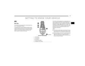 15
15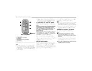 16
16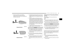 17
17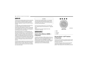 18
18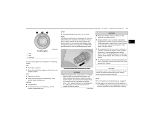 19
19 20
20 21
21 22
22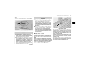 23
23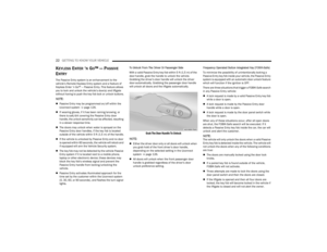 24
24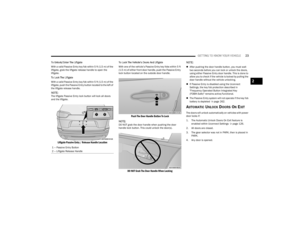 25
25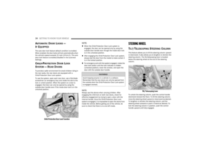 26
26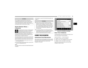 27
27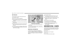 28
28 29
29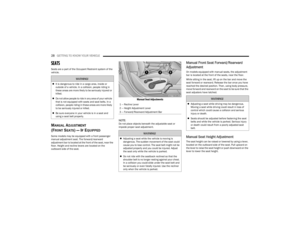 30
30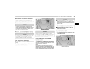 31
31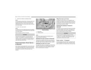 32
32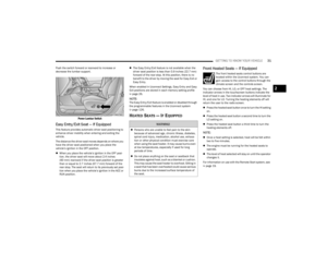 33
33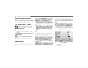 34
34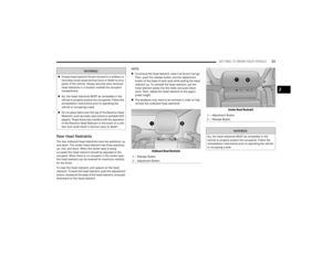 35
35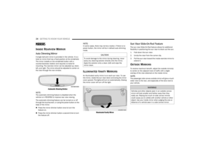 36
36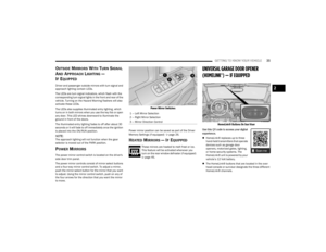 37
37 38
38 39
39 40
40 41
41 42
42 43
43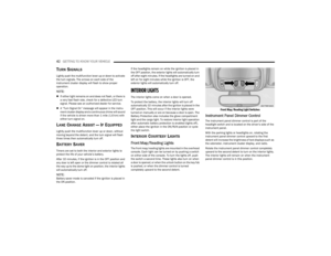 44
44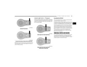 45
45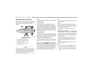 46
46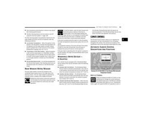 47
47 48
48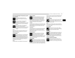 49
49 50
50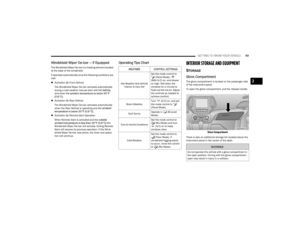 51
51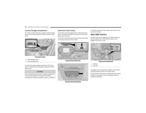 52
52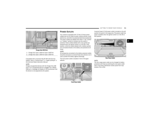 53
53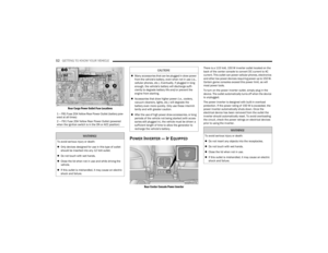 54
54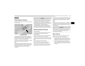 55
55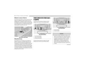 56
56 57
57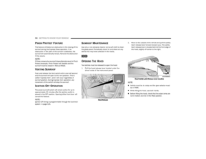 58
58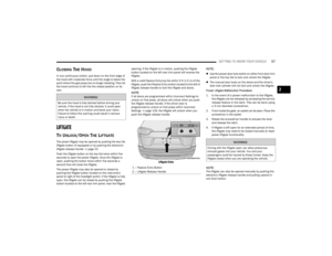 59
59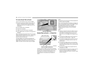 60
60 61
61 62
62 63
63 64
64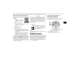 65
65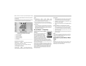 66
66 67
67 68
68 69
69 70
70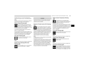 71
71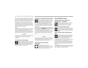 72
72 73
73 74
74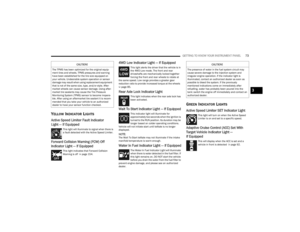 75
75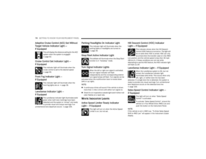 76
76 77
77 78
78 79
79 80
80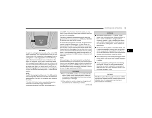 81
81 82
82 83
83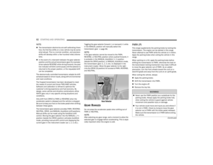 84
84 85
85 86
86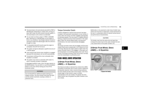 87
87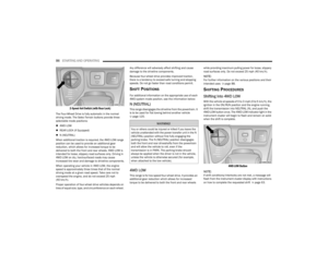 88
88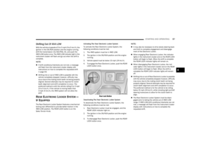 89
89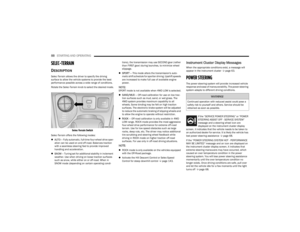 90
90 91
91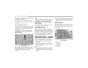 92
92 93
93 94
94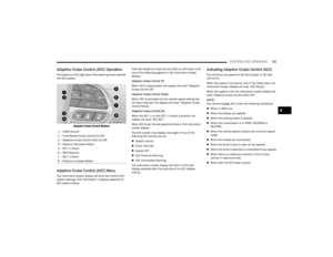 95
95 96
96 97
97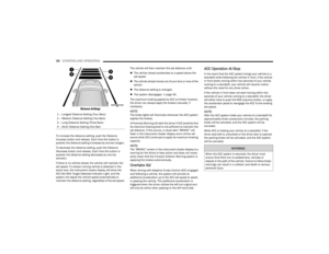 98
98 99
99 100
100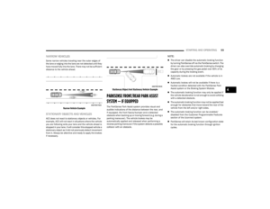 101
101 102
102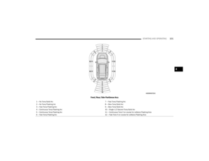 103
103 104
104 105
105 106
106 107
107 108
108 109
109 110
110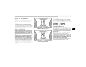 111
111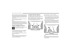 112
112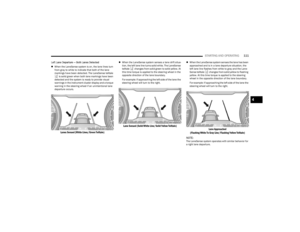 113
113 114
114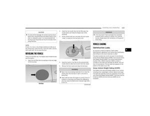 115
115 116
116 117
117 118
118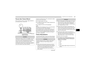 119
119 120
120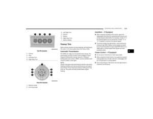 121
121 122
122 123
123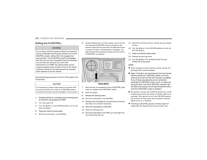 124
124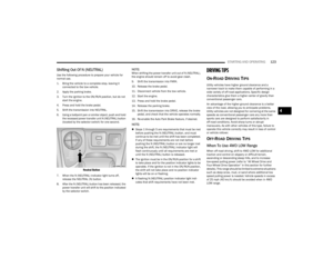 125
125 126
126 127
127 128
128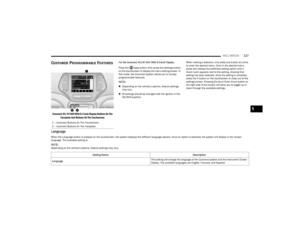 129
129 130
130 131
131 132
132 133
133 134
134 135
135 136
136 137
137 138
138 139
139 140
140 141
141 142
142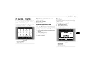 143
143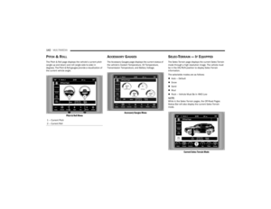 144
144 145
145 146
146 147
147 148
148 149
149 150
150 151
151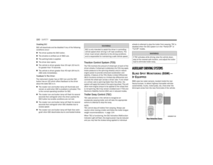 152
152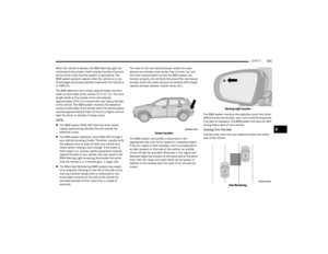 153
153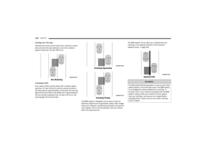 154
154 155
155 156
156 157
157 158
158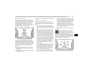 159
159 160
160 161
161 162
162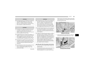 163
163 164
164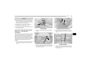 165
165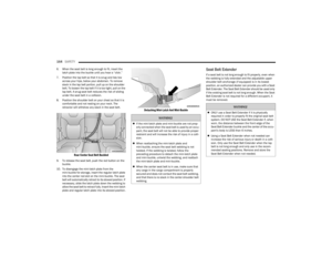 166
166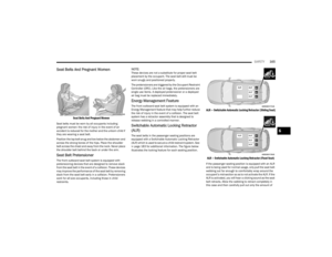 167
167 168
168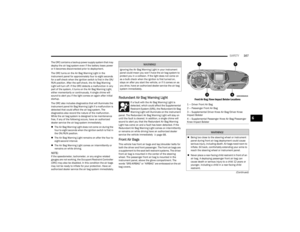 169
169 170
170 171
171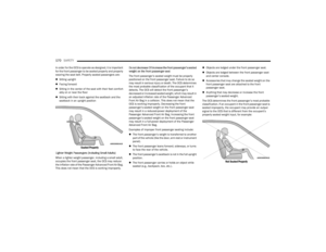 172
172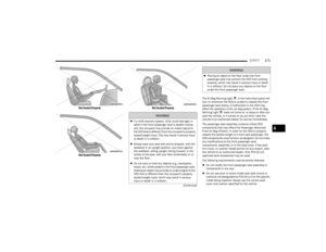 173
173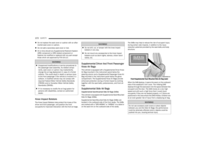 174
174 175
175 176
176 177
177 178
178 179
179 180
180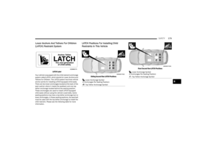 181
181 182
182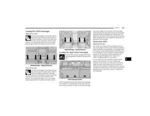 183
183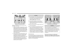 184
184 185
185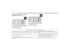 186
186 187
187 188
188 189
189 190
190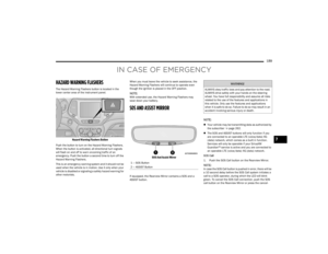 191
191 192
192 193
193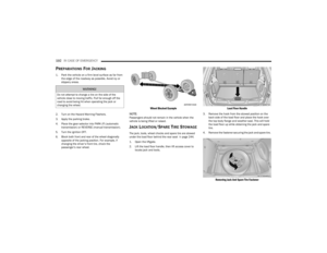 194
194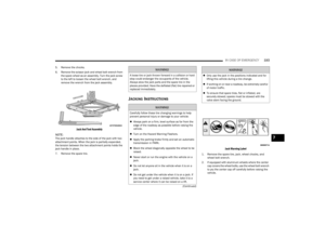 195
195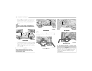 196
196 197
197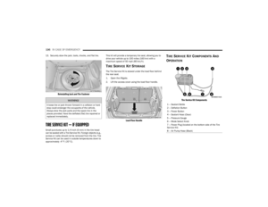 198
198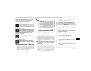 199
199 200
200 201
201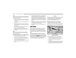 202
202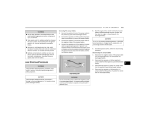 203
203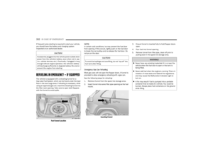 204
204 205
205 206
206 207
207 208
208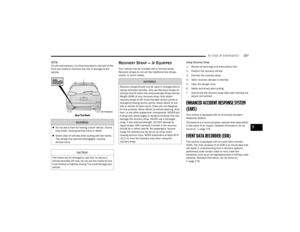 209
209 210
210 211
211 212
212 213
213 214
214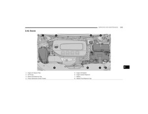 215
215 216
216 217
217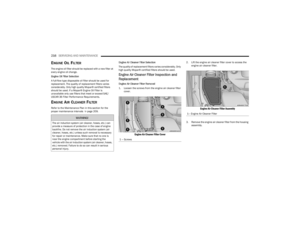 218
218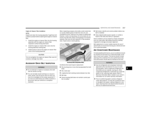 219
219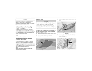 220
220 221
221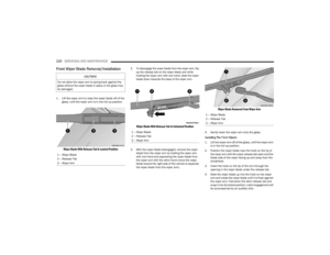 222
222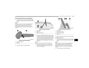 223
223 224
224 225
225 226
226 227
227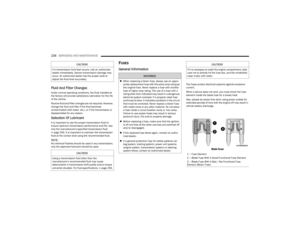 228
228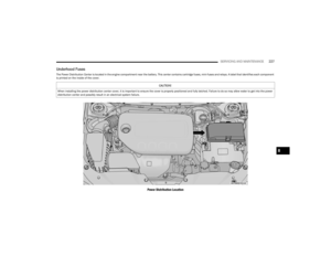 229
229 230
230 231
231 232
232 233
233 234
234 235
235 236
236 237
237 238
238 239
239 240
240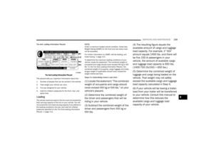 241
241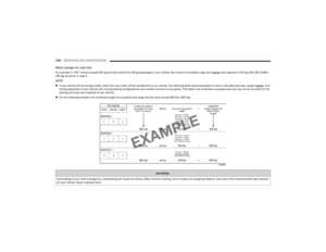 242
242 243
243 244
244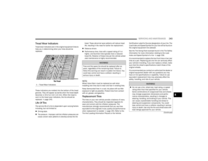 245
245 246
246 247
247 248
248 249
249 250
250 251
251 252
252 253
253 254
254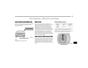 255
255 256
256 257
257 258
258 259
259 260
260 261
261 262
262 263
263 264
264 265
265 266
266 267
267 268
268 269
269 270
270 271
271 272
272 273
273 274
274 275
275