2023 HYUNDAI SONATA fuel
[x] Cancel search: fuelPage 508 of 555
Maintenance
8-38
WARNING
Tire failure may cause loss of vehicle
control resulting in an accident. To
reduce risk of SERIOUS INJURY or
DEATH, take the following precautions: • Inspect your tires monthly for proper
inflation as well as wear and damage.
• The recommended cold tire pressure
for your vehicle can be found in this
manual and on the tire label located
on the driver’s side center pillar.
Always use a tire pressure gauge to
measure tire pressure. Tires with
too much or too little pressure wear
unevenly causing poor handling.
• Check the pressure of the spare
every time you check the pressure of
the other tires on your vehicle.
• Replace tires that are worn, show
uneven wear, or are damaged.
Worn tires can cause loss of braking
effectiveness, steering control, or
traction.
• ALWAYS replace tires with the same
type, size, brand, construction and
tread pattern as each tire that was
originally supplied with this vehicle.
Using tires and wheels other than
the recommended sizes could cause
unusual handling characteristics,
poor vehicle control, or negatively
affect your vehicle’s Anti-Lock Brake
System (ABS) resulting in a serious
accident.Tire Care
For proper maintenance, safety, and
maximum fuel economy, you must
always maintain recommended tire
inflation pressures and stay within the
load limits and weight distribution
recommended for your vehicle.
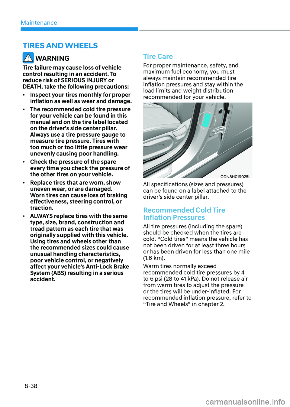
ODN8H019025L
All specifications (sizes and pressures)
can be found on a label attached to the
driver’s side center pillar.
Recommended Cold Tire
Inflation Pressures
All tire pressures (including the spare)
should be checked when the tires are
cold. “Cold tires” means the vehicle has
not been driven for at least three hours
or has been driven for less than one mile
(1.6 km).
Warm tires normally exceed
recommended cold tire pressures by 4
to 6 psi (28 to 41 kPa). Do not release air
from warm tires to adjust the pressure
or the tires will be under-inflated. For
recommended inflation pressure, refer to
“Tire and Wheels” in chapter 2.
tirES anD wHEELS
Page 509 of 555
08
8-39
WARNING
Recommended pressures must be
maintained for the best ride, vehicle
handling, and minimum tire wear.
Over-inflation or under-inflation can
reduce tire life, adversely affect vehicle
handling, and lead to sudden tire failure
that could result in loss of vehicle
control resulting in an accident.
Severe under-inflation can lead to
severe heat build-up, causing blowouts,
tread separation and other tire failures
that can result in the loss of vehicle
control resulting in an accident. This
risk is much higher on hot days and
when driving for long periods at high speeds.
CAUTION
• Under-inflation results in excessive
wear, poor handling and reduced
fuel economy. Wheel deformation
is also possible. Keep your tire
pressures at the proper levels. If a
tire frequently needs refilling, have it
checked by an authorized HYUNDAI
dealer.
• Over-inflation produces a harsh ride,
excessive wear at the center of the
tire tread, and a greater possibility of
damage from road hazards.
Check Tire Inflation Pressure
Check your tires, including the spare tire,
once a month or more.
How to check
Use a good quality tire pressure gauge
to check tire pressure. You can not tell
if your tires are properly inflated simply
by looking at them. Radial tires may look
properly inflated when they are under-
inflated.
Remove the valve cap from the tire valve
stem. Press the tire gauge firmly onto the
valve to get a pressure measurement.
If the cold tire inflation pressure
matches the recommended pressure
on the tire label located on the driver’s
side center pillar or in this manual. No
further adjustment is necessary. If the
pressure is low, add air until you reach
the recommended pressure. Make sure
to put the valve caps back on the valve
stems. Without the valve cap, dirt or
moisture could get into the valve core
and cause air leakage. If a valve cap is
missing, install a new one as soon as possible.
If you overfill the tire, release air by
pushing on the metal stem in the
center of the tire valve. Recheck the tire
pressure with the tire gauge. Be sure
to put the valve caps back on the valve
stems. Without the valve cap, dirt or
moisture could get into the valve core
and cause air leakage. If a valve cap is
missing, install a new one as soon as possible.
A cold tire means the vehicle has been
sitting for 3 hours and driven for less
than 1.6 km (1 mile) in that 3 hour period.
Allow the tire to cool before measuring
the inflation pressure. Always be sure
the tire is cold before inflating to the
recommended pressure.
Page 515 of 555
08
8-45
WARNING
The traction grade assigned to this tire
is based on straight-ahead braking
traction tests, and does not include
acceleration, cornering, hydroplaning,
or peak traction characteristics.
Temperature A, B & C
The temperature grades are A (the
highest), B and C representing the tire’s
resistance to the generation of heat
and its ability to dissipate heat when
tested under controlled conditions on a
specified indoor laboratory test wheel.
Sustained high temperature can cause
the material of the tire to degenerate
and reduce tire life, and excessive
temperature can lead to sudden tire
failure.
WARNING
The temperature grade for this tire is
established for a tire that is properly
inflated and not overloaded. Excessive
speed, under-inflation, over-inflation,
or excessive loading, either separately
or in combination, can cause heat build-
up and possible sudden tire failure.
This may cause loss of vehicle control
resulting in an accident.
Tire Terminology and Definitions
Air Pressure
The amount of air inside the tire pressing
outward on the tire. Air pressure is
expressed in kilopascal (kPa) or pounds
per square inch (psi).
Accessory Weight
This means the combined weight of
optional accessories. Some examples
of optional accessories are automatic
transmission, power seats, and air conditioning.
Aspect Ratio
The relationship of a tire’s height to its width. Belt
A rubber coated layer of cords that is
located between the plies and the tread.
Cords may be made from steel or other
reinforcing materials. Bead
The tire bead contains steel wires
wrapped by steel cords that hold the tire
onto the rim.
Bias Ply Tire
A pneumatic tire in which the plies are
laid at alternate angles less than 90
degrees to the centerline of the tread.
Cold Tire Pressure
The amount of air pressure in a tire,
measured in kilopascals (kPa) or pounds
per square inch (psi) before a tire has
built up heat from driving.
Curb Weight
This means the weight of a motor vehicle
with standard and optional equipment
including the maximum capacity of fuel,
oil and coolant, but without passengers
and cargo.
Page 527 of 555
08
8-57
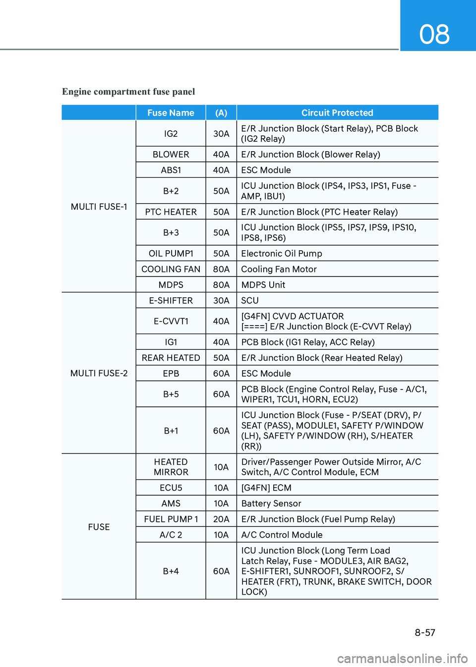
Engine compartment fuse panel
Fuse Name (A) Circuit Protected
MULTI FUSE-1 IG2 30A
E/R Junction Block (Start Relay), PCB Block
(IG2 Relay)
BLOWER 40A E/R Junction Block (Blower Relay) ABS1 40A ESC Module
B+2 50A ICU Junction Block (IPS4, IPS3, IPS1, Fuse -
AMP, IBU1)
PTC HEATER 50A E/R Junction Block (PTC Heater Relay)
B+3 50A ICU Junction Block (IPS5, IPS7, IPS9, IPS10, IPS8, IPS6)
OIL PUMP1 50A Electronic Oil Pump
COOLING FAN 80A Cooling Fan Motor MDPS 80A MDPS Unit
MULTI FUSE-2 E-SHIFTER 30A SCU
E-CVVT1 40A [G4FN] CVVD ACTUATOR
[====] E/R Junction Block (E-CVVT Relay)
IG1 40A PCB Block (IG1 Relay, ACC Relay)
REAR HEATED 50A E/R Junction Block (Rear Heated Relay)
EPB 60A ESC Module
B+5 60A PCB Block (Engine Control Relay, Fuse - A/C1,
WIPER1, TCU1, HORN, ECU2)
B+1 60A ICU Junction Block (Fuse - P/SEAT (DRV), P/
SEAT (PASS), MODULE1, SAFETY P/WINDOW
(LH), SAFETY P/WINDOW (RH), S/HEATER
(RR))
FUSE HEATED
MIRROR 10A Driver/Passenger Power Outside Mirror, A/C
Switch, A/C Control Module, ECM
ECU5 10A [G4FN] ECM AMS 10A Battery Sensor
FUEL PUMP 1 20A E/R Junction Block (Fuel Pump Relay) A/C 2 10A A/C Control Module
B+4 60A ICU Junction Block (Long Term Load
Latch Relay, Fuse - MODULE3, AIR BAG2,
E-SHIFTER1, SUNROOF1, SUNROOF2, S/
HEATER (FRT), TRUNK, BRAKE SWITCH, DOOR
LOCK)
Page 536 of 555
Maintenance
8-66
Repairing your vehicle’s finish
Deep scratches or stone chips in the
painted surface must be repaired
promptly. Exposed metal will quickly
rust and may develop into a major repair
expense.
NOTICE
If your vehicle is damaged and requires
any metal repair or replacement,
be sure the body shop applies anti-
corrosion materials to the parts
repaired or replaced.
NOTICE
Matte paint finish vehicle (if equipped)
In case of matte paint finish vehicles,
it is impossible to modify only the
damaged area and repair of the whole
part is necessary. If the vehicle is
damaged and painting is required,
we recommend that you have your
vehicle maintained and repaired by
an authorized HYUNDAI dealer. Take
extreme care, as it is difficult to restore
the quality after the repair.
Bright-metal maintenance • To remove road tar and insects, use
a tar remover, not a scraper or other sharp object.
• To protect the surfaces of bright metal
parts from corrosion, apply a coating
of wax or chrome preservative and rub
to a high luster.
• During winter weather or in coastal
areas, cover the bright metal parts
with a heavier coating of wax or
preservative. If necessary, coat the
parts with non-corrosive petroleum
jelly or other protective compound. Underbody maintenance
Corrosive materials used for ice and
snow removal and dust control may
collect on the underbody. If these
materials are not removed, accelerated
rusting can occur on underbody parts
such as the fuel lines, frame, floor pan
and exhaust system, even though they
have been treated with rust protection.
Thoroughly flush the vehicle underbody
and wheel openings with lukewarm or
cold water once a month, after off-road
driving and at the end of each winter. Pay
special attention to these areas because
it is difficult to see all the mud and dirt.
It will do more harm than good to wet
down the road grime without removing
it. The lower edges of doors, rocker
panels, and frame members have drain
holes that should not be allowed to clog
with dirt; trapped water in these areas
can cause rusting.
WARNING
After washing the vehicle, test the
brakes while driving slowly to see if
they have been affected by water. If
braking performance is impaired, dry
the brakes by applying them lightly
while maintaining a slow forward speed.
Aluminum wheel maintenance
The aluminum wheels are coated with a
clear protective finish.
Page 541 of 555
08
8-71
1. Crankcase Emission Control System
The positive crankcase ventilation system
is employed to prevent air pollution
caused by blow-by gases being emitted
from the crankcase. This system supplies
fresh filtered air to the crankcase through
the air intake hose. Inside the crankcase,
the fresh air mixes with blow-by gases,
which then pass through the PCV valve
into the induction system.
2. Evaporative Emission Control System Including Onboard
Refueling Vapor Recovery
(ORVR)
The Evaporative Emission Control System
is designed to prevent fuel vapors from
escaping into the atmosphere. The
ORVR system is designed to allow the
vapors from the fuel tank to be loaded
into a canister while refueling at the gas
station, preventing the escape of fuel
vapors into the atmosphere.
Canister
Fuel vapors generated inside the fuel
tank are absorbed and stored in the
onboard canister. When the engine is
running, the fuel vapors absorbed in the
canister are drawn into the surge tank
through the purge control solenoid valve.
Purge Control Solenoid Valve (PCSV)
The purge control solenoid valve
is controlled by the Engine Control
Module (ECM); when the engine coolant
temperature is low during idling, the
PCSV closes so that evaporated fuel
is not taken into the engine. After the
engine warms-up during ordinary
driving, the PCSV opens to introduce
evaporated fuel to the engine.
3. Exhaust Emission Control System
The Exhaust Emission Control System is
a highly effective system which controls
exhaust emissions while maintaining
good vehicle performance.
When the engine starts or fails to start,
excessive attempts to restart the engine
may cause damage to the emission
system.
Engine exhaust (carbon monoxide)
precautions • Carbon monoxide can be present
with other exhaust fumes. If you smell
exhaust fumes of any kind in your
vehicle, drive with all the windows
fully open. Have your vehicle checked
and repaired immediately.
WARNING
Engine exhaust gases contain carbon
monoxide (CO). Though colorless and
odorless, it is dangerous and could be
lethal if inhaled. Follow the instructions
on this page to avoid CO poisoning.
Page 542 of 555
Maintenance
8-72
•
Do not operate the engine in confined
or closed areas (such as garages) any
more than what is necessary to move
the vehicle in or out of the area.
• When the vehicle is stopped in an
open area for more than a short time
with the engine running, adjust the
ventilation system (as needed) to draw
outside air into the vehicle.
• Never sit in a parked or stopped
vehicle for any extended time with the engine running.
• When the engine stalls or fails to
start, excessive attempts to restart
the engine may cause damage to the
emission control system.
Operating precautions for catalytic
converters (if equipped)
WARNING
The exhaust system and catalytic
converter are very hot during and
immediately after the engine has been
running. To avoid SERIOUS INJURY or
DEATH: • Do not park, idle, or drive the vehicle
over or near flammable objects, such
as grass, vegetation, paper, leaves,
etc. A hot exhaust system can ignite
flammable items under your vehicle.
• Keep away from the exhaust system
and catalytic converter or you may
get burned.
Also, do not remove the heat sink
around the exhaust system, do not
seal the bottom of the vehicle, and
do not coat the vehicle for corrosion
control. It may present a fire risk
under certain conditions. Your vehicle is equipped with a catalytic
converter emission control device.
To prevent damage to the catalytic
converter and to your vehicle, take the
following precautions: •
Use only UNLEADED FUEL for gasoline engines.
• Do not operate the vehicle when
there are signs of engine malfunction,
such as misfire or a noticeable loss of
performance.
• Do not misuse or abuse the engine.
Examples of misuse are coasting with
the engine off and descending steep
grades in gear with the engine off.
• Do not operate the engine at high
idle speed for extended periods (5
minutes or more).
• Do not modify or tamper with any
part of the engine or emission
control system. All inspections and
adjustments must be made by an
authorized HYUNDAI dealer.
• Avoid driving with extremely low
fuel level. If you run out of gasoline,
it could cause the engine to misfire
and result in excessive loading of the
catalytic converter.
Page 547 of 555
I
I-5
E Emission Control System .................................................................................... 8-70
Engine Compartment ..................................................................................... 2-8/ 8-3
Engine Coolant .................................................................................................... 8-26
Changing Engine Coolant ................................................................................ 8-28
Checking the Engine Coolant Level ................................................................. 8-26
Engine Number .................................................................................................... 2-17
Engine Oil ............................................................................................................ 8-23
Checking the Engine Oil and Filter .................................................................. 8-25
Checking the Engine Oil Level ........................................................................ 8-23
Engine Specification ............................................................................................ 2-10
Explanation of Scheduled Maintenance Items ....................................................8-20
Exterior Features .................................................................................................. 5-50
Emergency Trunk Safety Release..................................................................... 5-52
Fuel Filler Door ................................................................................................ 5-56
Hood ................................................................................................................. 5-50
Trunk ................................................................................................................ 5-51
Exterior Overview ................................................................................................. 2-2
F
Forward Collision – Avoidance Assist (FCA) - Sensor Fusion ...........................6-50
FCA Sensor ...................................................................................................... 6-55
FCA Warning Message And Brake Control .....................................................6-52
Forward Collision-Avoidance Assist - Junction Turning ................................6-65
Limitations of The System ............................................................................... 6-58
System Malfunction ......................................................................................... 6-57
System Setting and Activation ......................................................................... 6-50
Forward/Reverse Parking Distance Warning (PDW) ..........................................5-86
Forward/Reverse Parking Distance Warning System Precautions ...................5-90
Non-Operational Conditions of Forward/Reverse Parking Distance
Warning System ............................................................................................. 5-89
Operation of Forward/Reverse Parking Distance Warning System .................5-87
Fuel Requirements ................................................................................................. 1-5
Fuses .................................................................................................................... 8-50
Engine Compartment Panel Fuse Replacement ...............................................8-52
Fuse/Relay Panel Description .......................................................................... 8-53
Instrument Panel Fuse Replacement ................................................................ 8-51