2023 HYUNDAI SONATA maintenance
[x] Cancel search: maintenancePage 516 of 555
Maintenance
8-46Maximum Inflation Pressure
The maximum air pressure to which a
cold tire may be inflated. The maximum
air pressure is molded onto the sidewall.
Maximum Load Rating
The load rating for a tire at the maximum
permissible inflation pressure for that
tire.
Maximum Loaded Vehicle Weight
The sum of curb weight; accessory
weight; vehicle capacity weight; and
production options weight.
Normal Occupant Weight
The number of occupants a vehicle is
designed to seat multiplied by 68 kg (150
pounds).
Occupant Distribution
Designated seating positions.
Outward Facing Sidewall
An asymmetrical tire has a particular
side that faces outward when mounted
on a vehicle. The outward facing
sidewall bears white lettering or bears
manufacturer, brand, and/or model
name molding that is higher or deeper than the same moldings on the inner
facing sidewall.
Passenger (P-Metric) tire
A tire used on passenger cars and some
light duty trucks and multipurpose
vehicles. Ply
A layer of rubber-coated parallel cords.
DOT Markings
The DOT code includes the Tire
Identification Number (TIN), an
alphanumeric designator which can
also identify the tire manufacturer,
production plant, brand and date of
production.
GVWR
Gross Vehicle Weight Rating
GAWR FRT
Gross Axle Weight Rating for the Front Axle.
GAWR RR
Gross Axle Weight Rating for the Rear axle.
Intended Outboard Sidewall
The side of an asymmetrical tire,
that must always face outward when
mounted on a vehicle.
Kilopascal (kPa)
The metric unit for air pressure.
Light truck (LT) tire
A tire designated by its manufacturer as
primarily intended for use on lightweight
trucks or multipurpose passenger
vehicles.
Load ratings
The maximum load that a tire is rated to
carry for a given inflation pressure.
Load Index
An assigned number ranging from 1 to
279 that corresponds to the load carrying
capacity of a tire.
Page 518 of 555
Maintenance
8-48
All Season Tires
HYUNDAI specifies all season tires
on some models to provide good
performance for use all year round,
including snowy and icy road conditions.
All season tires are identified by ALL
SEASON and/or M+S (Mud and Snow) on
the tire sidewall. Snow tires have better
snow traction than all season tires and
may be more appropriate in some areas.
Summer Tires
HYUNDAI specifies summer tires on
some models to provide superior
performance on dry roads. Summer tire
performance is substantially reduced in
snow and ice. Summer tires do not have
the tire traction rating M+S (Mud and
Snow) on the tire side wall. If you plan
to operate your vehicle in snowy or icy
conditions, HYUNDAI recommends the
use of snow tires or all season tires on all
four wheels.
Snow Tires
If you equip your car with snow tires,
they should be the same size and have the same load capacity as the original
tires. Snow tires should be installed on
all four wheels; otherwise, poor handling
may result. Snow tires should carry 28
kPa (4 psi) more air pressure than the
pressure recommended for the standard
tires on the tire label on the driver’s
side of the center pillar, or up to the
maximum pressure shown on the tire
sidewall, whichever is less. Do not drive
faster than 120 km/h (75 mph) when your
vehicle is equipped with snow tires.
Radial-Ply Tires
Radial-ply tires provide improved tread
life, road hazard resistance and smoother
high speed ride. The radial-ply tires used
on this vehicle are of belted construction,
and are selected to complement the
ride and handling characteristics of your
vehicle.
Radial-ply tires have the same load
carrying capacity, as bias-ply or bias
belted tires of the same size, and use the
same recommended inflation pressure.
Mixing of radial-ply tires with bias-ply or
bias belted tires is not recommended.
Any combinations of radial-ply and bias-
ply or bias belted tires when used on the
same vehicle will seriously deteriorate
vehicle handling. The best rule to follow
is: Identical pairs of radial-ply tires
should always be used as a set for the
front tires and a set for the rear tires.
Longer wearing tires can be more
susceptible to irregular tread wear. It is
very important to follow the tire rotation
interval in this chapter to achieve the
tread life potential of these tires. Cuts
and punctures in radial-ply tires are
repairable only in the tread area, because
of sidewall flexing. Consult your tire
dealer for radial-ply tire repairs.
WARNING
Do not mix bias ply and radial ply tires
under any circumstances. This may
cause unusual handling characteristics
that may cause loss of vehicle control
resulting in an accident.
Page 520 of 555
Maintenance
8-50
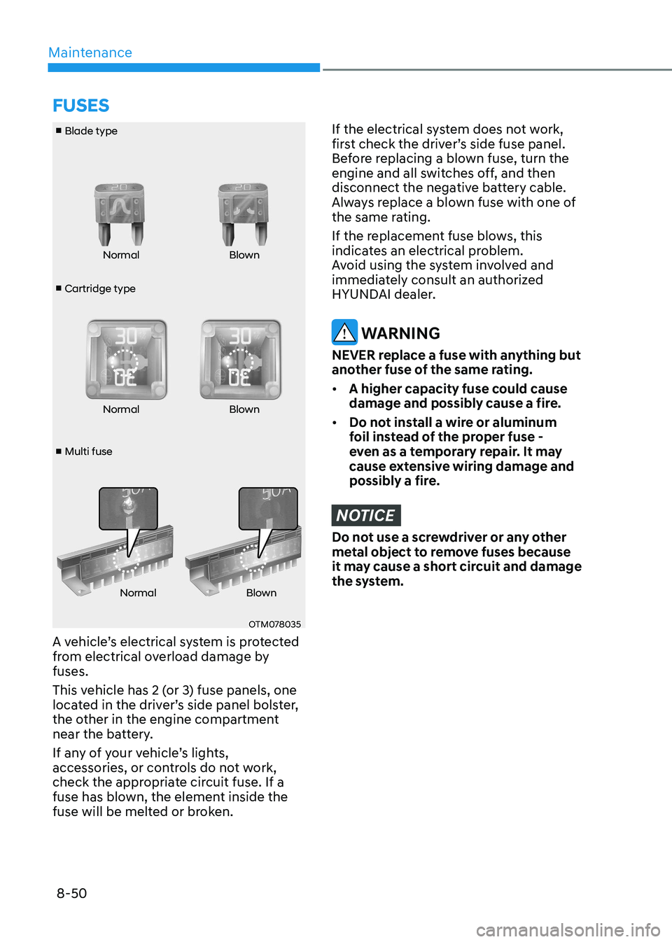
■ Cartridge type
■ Blade type
■ Multi fuse Normal Blown
Normal Blown
Normal Blown
OTM078035
A vehicle’s electrical system is protected
from electrical overload damage by fuses.
This vehicle has 2 (or 3) fuse panels, one
located in the driver’s side panel bolster,
the other in the engine compartment
near the battery.
If any of your vehicle’s lights,
accessories, or controls do not work,
check the appropriate circuit fuse. If a
fuse has blown, the element inside the
fuse will be melted or broken.
If the electrical system does not work,
first check the driver’s side fuse panel.
Before replacing a blown fuse, turn the
engine and all switches off, and then
disconnect the negative battery cable.
Always replace a blown fuse with one of
the same rating.
If the replacement fuse blows, this
indicates an electrical problem.
Avoid using the system involved and
immediately consult an authorized
HYUNDAI dealer.
WARNING
NEVER replace a fuse with anything but
another fuse of the same rating. • A higher capacity fuse could cause
damage and possibly cause a fire.
• Do not install a wire or aluminum
foil instead of the proper fuse -
even as a temporary repair. It may
cause extensive wiring damage and
possibly a fire.
NOTICE
Do not use a screwdriver or any other
metal object to remove fuses because
it may cause a short circuit and damage
the system.
fUSES
Page 522 of 555
Maintenance
8-52
Engine Compartment Panel Fuse
Replacement
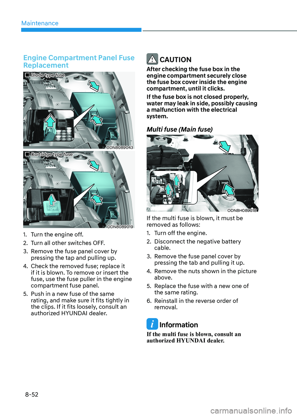
„„Blade type fuse
ODN8089043
„„Cartridge type fuse
ODN8089019
1. Turn the engine off.
2. Turn all other switches OFF.
3. Remove the fuse panel cover by pressing the tap and pulling up.
4. Check the removed fuse; replace it
if it is blown. To remove or insert the fuse, use the fuse puller in the engine
compartment fuse panel.
5. Push in a new fuse of the same rating, and make sure it fits tightly in
the clips. If it fits loosely, consult an
authorized HYUNDAI dealer.
CAUTION
After checking the fuse box in the
engine compartment securely close
the fuse box cover inside the engine
compartment, until it clicks.
If the fuse box is not closed properly,
water may leak in side, possibly causing a malfunction with the electrical
system.
Multi fuse (Main fuse)
ODN8H089018
If the multi fuse is blown, it must be
removed as follows:
1. Turn off the engine.
2. Disconnect the negative battery cable.
3. Remove the fuse panel cover by pressing the tab and pulling it up.
4. Remove the nuts shown in the picture
above.
5. Replace the fuse with a new one of the same rating.
6. Reinstall in the reverse order of removal.
Information
If the multi fuse is blown, consult an
authorized HYUNDAI dealer.
Page 524 of 555
Maintenance
8-54
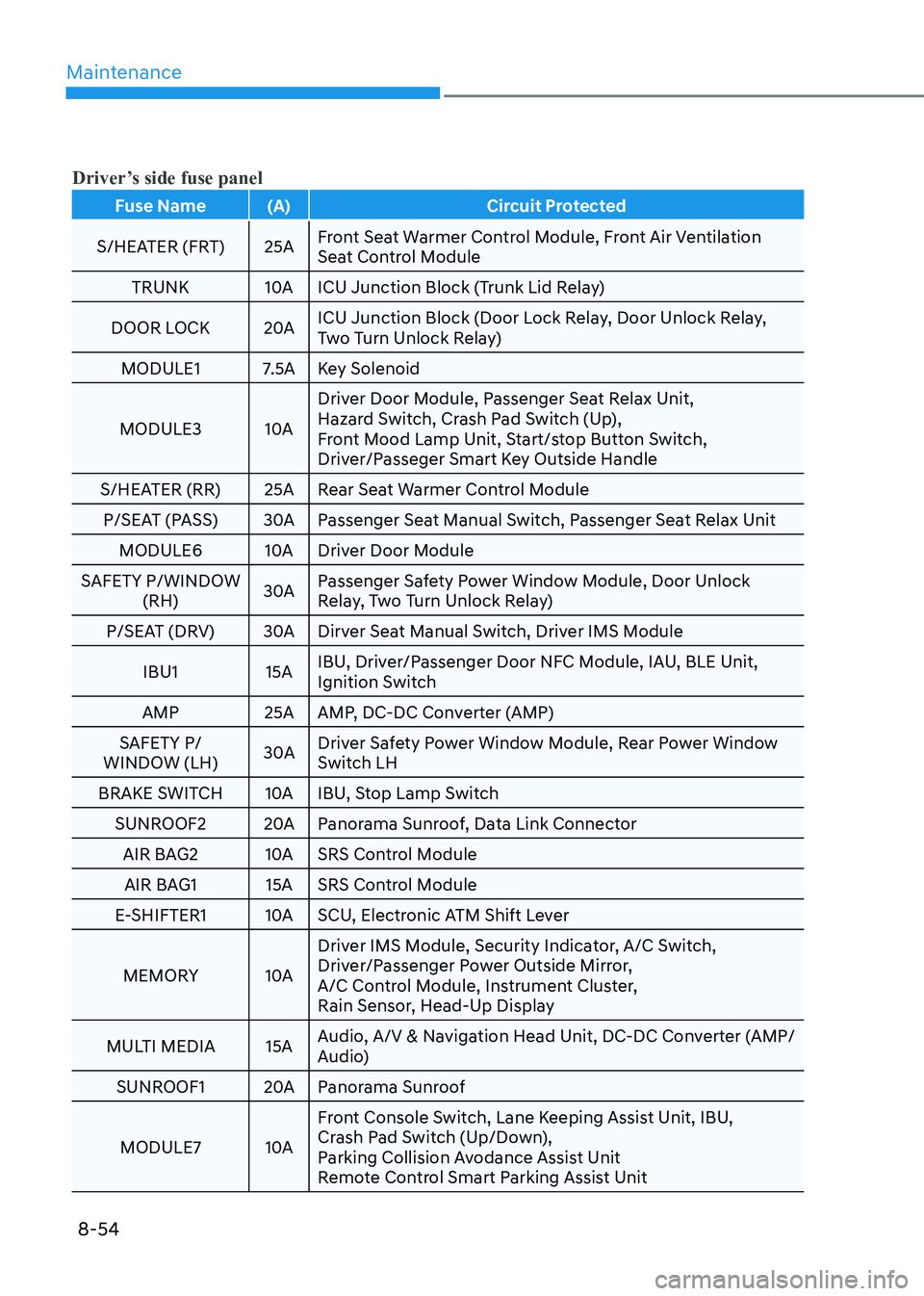
Driver’s side fuse panel
Fuse Name (A) Circuit Protected
S/HEATER (FRT) 25A Front Seat Warmer Control Module, Front Air Ventilation
Seat Control Module
TRUNK 10A ICU Junction Block (Trunk Lid Relay)
DOOR LOCK 20A ICU Junction Block (Door Lock Relay, Door Unlock Relay,
Two Turn Unlock Relay)
MODULE1 7.5A Key Solenoid
MODULE3 10A Driver Door Module, Passenger Seat Relax Unit,
Hazard Switch, Crash Pad Switch (Up),
Front Mood Lamp Unit, Start/stop Button Switch,
Driver/Passeger Smart Key Outside Handle
S/HEATER (RR) 25A Rear Seat Warmer Control Module P/SEAT (PASS) 30A Passenger Seat Manual Switch, Passenger Seat Relax Unit MODULE6 10A Driver Door Module
SAFETY P/WINDOW (RH) 30A Passenger Safety Power Window Module, Door Unlock
Relay, Two Turn Unlock Relay)
P/SEAT (DRV) 30A Dirver Seat Manual Switch, Driver IMS Module
IBU1 15A IBU, Driver/Passenger Door NFC Module, IAU, BLE Unit,
Ignition Switch
AMP 25A AMP, DC-DC Converter (AMP)
SAFETY P/
WINDOW (LH) 30A Driver Safety Power Window Module, Rear Power Window
Switch LH
BRAKE SWITCH 10A IBU, Stop Lamp Switch SUNROOF2 20A Panorama Sunroof, Data Link Connector
AIR BAG2 10A SRS Control Module AIR BAG1 15A SRS Control Module
E-SHIFTER1 10A SCU, Electronic ATM Shift Lever
MEMORY 10A Driver IMS Module, Security Indicator, A/C Switch,
Driver/Passenger Power Outside Mirror,
A/C Control Module, Instrument Cluster,
Rain Sensor, Head-Up Display
MULTI MEDIA 15A Audio, A/V & Navigation Head Unit, DC-DC Converter (AMP/
Audio)
SUNROOF1 20A Panorama Sunroof
MODULE7 10A Front Console Switch, Lane Keeping Assist Unit, IBU,
Crash Pad Switch (Up/Down),
Parking Collision Avodance Assist Unit
Remote Control Smart Parking Assist Unit
Page 526 of 555
Maintenance
8-56
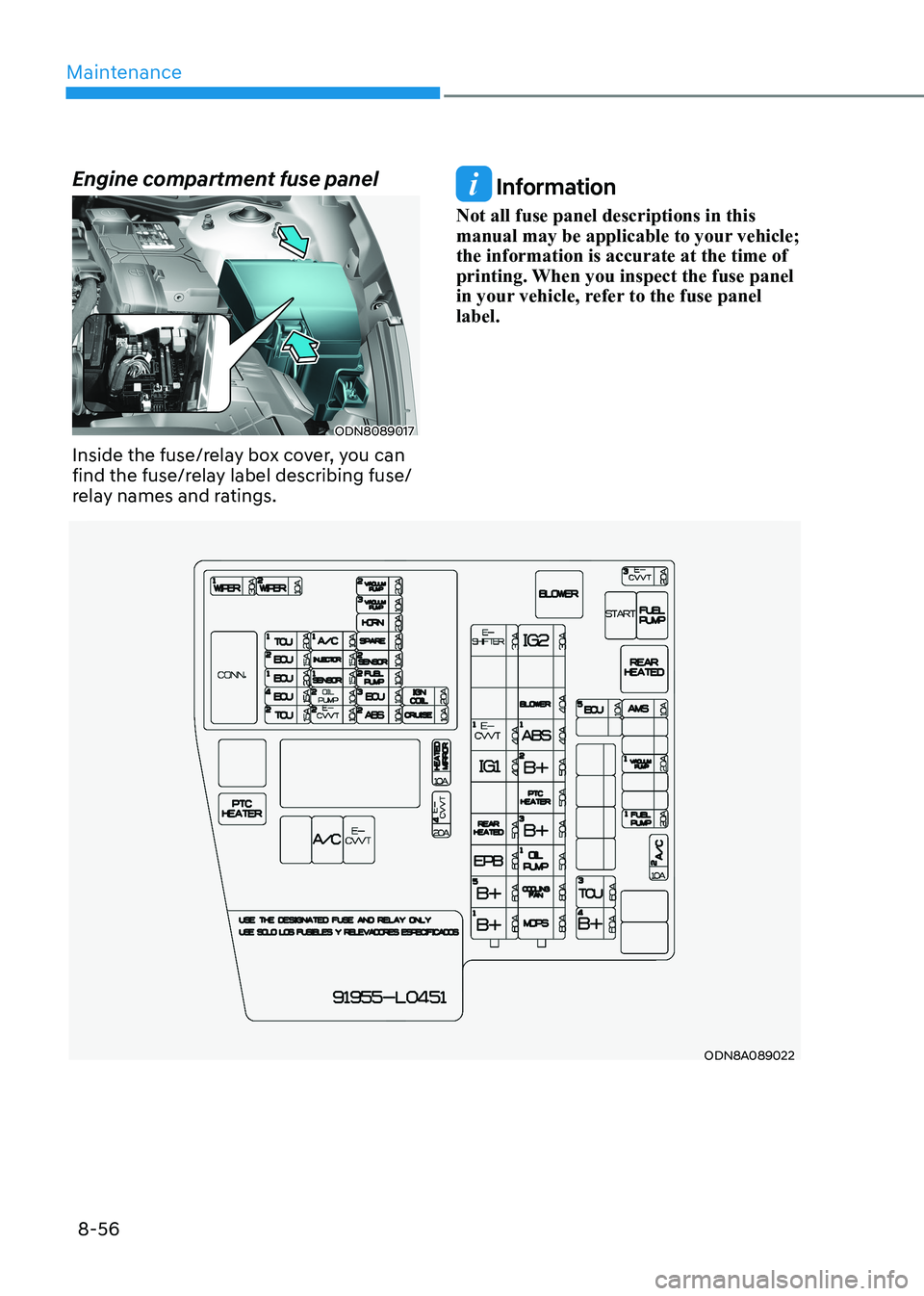
ODN8A089022
Engine compartment fuse panel
ODN8089017
Inside the fuse/relay box cover, you can
find the fuse/relay label describing fuse/
relay names and ratings.
Information
Not all fuse panel descriptions in this
manual may be applicable to your vehicle; the information is accurate at the time of
printing. When you inspect the fuse panel
in your vehicle, refer to the fuse panel label.
Page 528 of 555
Maintenance
8-58
Consult an authorized HYUNDAI dealer
to replace most vehicle light bulbs. It is
difficult to replace vehicle light bulbs
because other parts of the vehicle must
be removed before you can get to the
bulb. This is especially true for removing
the headlamp assembly to get to the
bulb(s).
Removing/installing the headlamp
assembly can result in damage to the
vehicle.
Information
The headlamp and tail lamp lenses could
appear frosty if the vehicle is washed after
driving or the vehicle is driven at night
in wet weather. This condition is caused
by temperature difference between the lamp inside and outside and, it does not
indicate a problem with your vehicle.
When moisture condenses in the lamp,
it will be removed after driving with the
headlamp on. The removable level may
differ depending on lamp size, lamp
position and environmental condition.
However, if moisture is not removed, we
recommend that your vehicle is inspected
by an authorized HYUNDAI dealer.
WARNING
• Prior to replacing a lamp, depress
the foot brake, move the shift button
into P (Park) apply the parking brake,
place the ignition switch to the
LOCK/OFF position, and take the key
with you when leaving the vehicle
to avoid sudden movement of the
vehicle and to prevent possible electric shock.
• Be aware the bulbs may be hot and
may burn your fingers.
Headlamp, Parking Lamp,
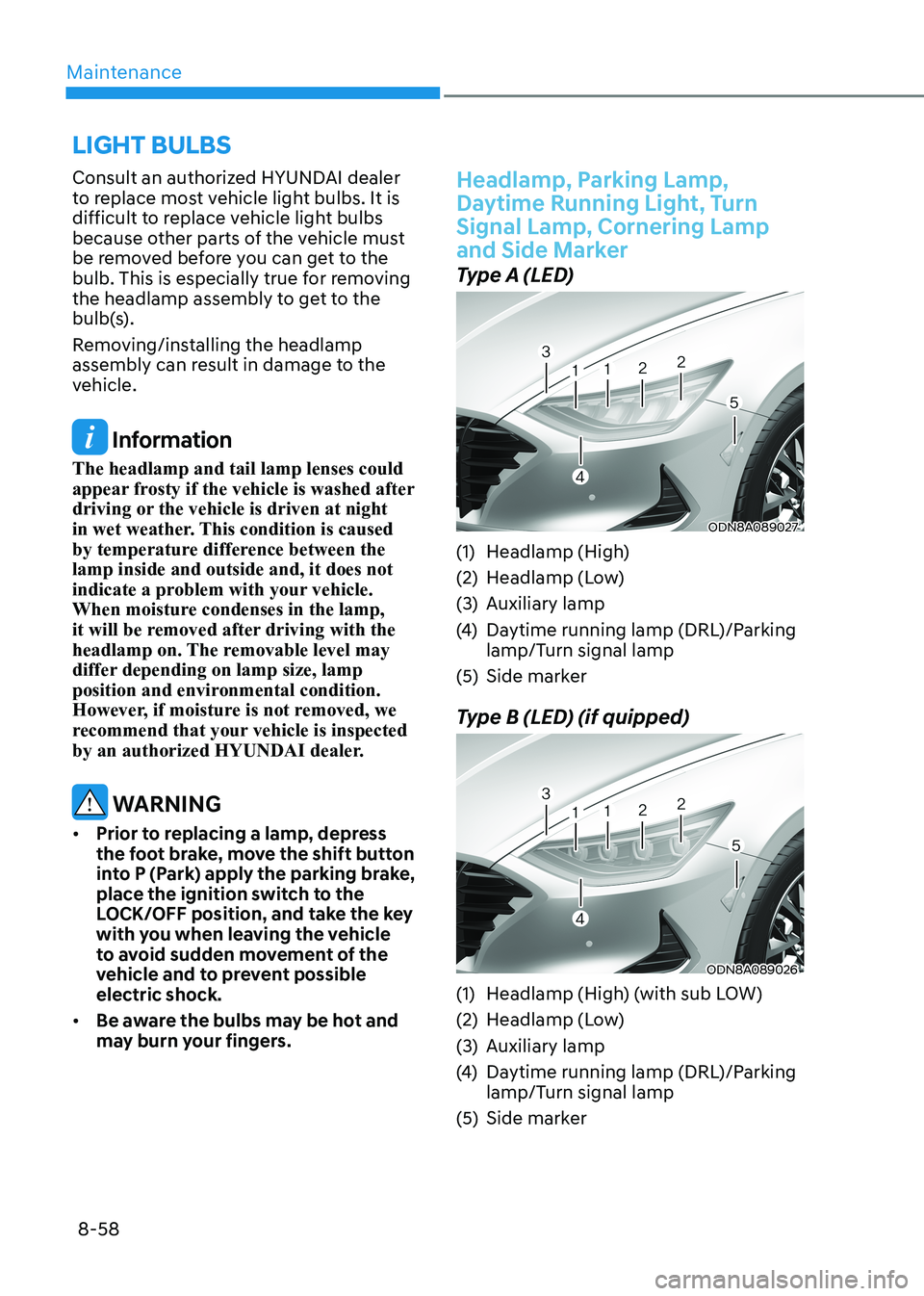
Daytime Running Light, Turn Signal Lamp, Cornering Lamp
and Side Marker
Type A (LED)
ODN8A089027
(1) Headlamp (High)
(2) Headlamp (Low)
(3) Auxiliary lamp
(4) Daytime running lamp (DRL)/Parking
lamp/Turn signal lamp
(5) Side marker
Type B (LED) (if quipped)
ODN8A089026
(1) Headlamp (High) (with sub LOW)
(2) Headlamp (Low)
(3) Auxiliary lamp
(4) Daytime running lamp (DRL)/Parking
lamp/Turn signal lamp
(5) Side marker
LigHt BULBS
Page 530 of 555
Maintenance
8-60
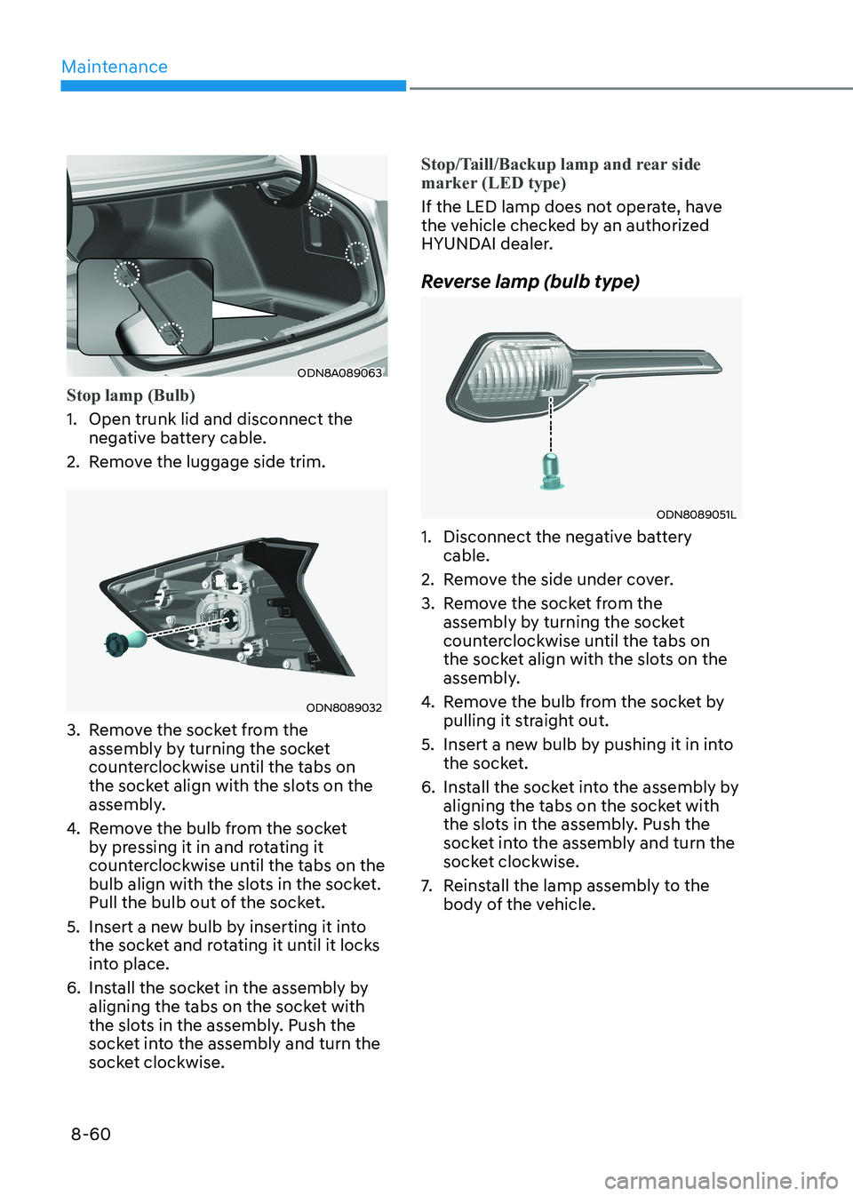
ODN8A089063
Stop lamp (Bulb)
1. Open trunk lid and disconnect the negative battery cable.
2. Remove the luggage side trim.
ODN8089032
3. Remove the socket from the assembly by turning the socket
counterclockwise until the tabs on
the socket align with the slots on the
assembly.
4. Remove the bulb from the socket
by pressing it in and rotating it
counterclockwise until the tabs on the
bulb align with the slots in the socket.
Pull the bulb out of the socket.
5. Insert a new bulb by inserting it into the socket and rotating it until it locks
into place.
6. Install the socket in the assembly by aligning the tabs on the socket with
the slots in the assembly. Push the
socket into the assembly and turn the
socket clockwise.
Stop/Taill/Backup lamp and rear side
marker (LED type)
If the LED lamp does not operate, have
the vehicle checked by an authorized
HYUNDAI dealer.
Reverse lamp (bulb type)
ODN8089051L
1. Disconnect the negative battery cable.
2. Remove the side under cover.
3. Remove the socket from the assembly by turning the socket
counterclockwise until the tabs on
the socket align with the slots on the
assembly.
4. Remove the bulb from the socket by
pulling it straight out.
5. Insert a new bulb by pushing it in into the socket.
6. Install the socket into the assembly by aligning the tabs on the socket with
the slots in the assembly. Push the
socket into the assembly and turn the
socket clockwise.
7. Reinstall the lamp assembly to the
body of the vehicle.