2023 HYUNDAI SONATA radio
[x] Cancel search: radioPage 289 of 555
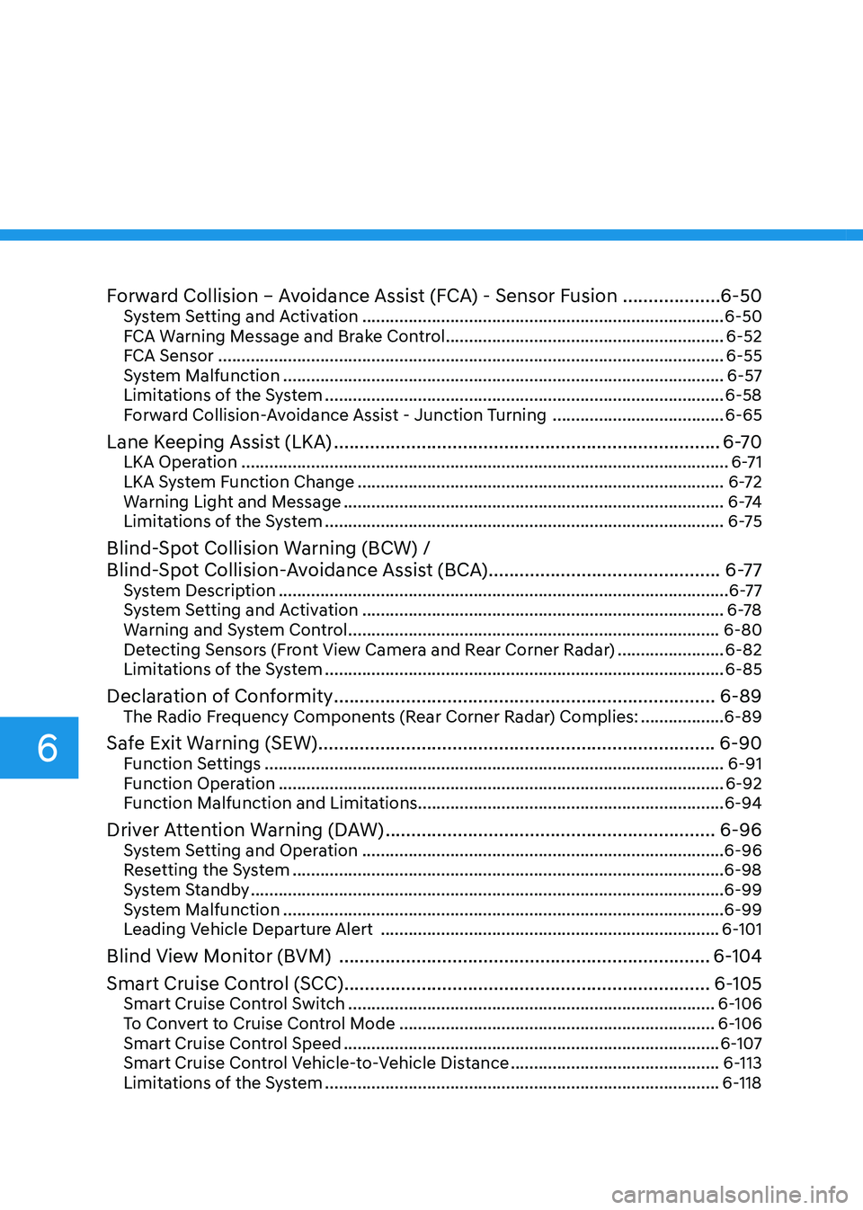
Forward Collision – Avoidance Assist (FCA) - Sensor Fusion ...................6-50
System Setting and Activation .............................................................................. 6-50
FCA Warning Message and Brake Control ............................................................6-52
FCA Sensor ............................................................................................................. 6-55
System Malfunction ............................................................................................... 6-57
Limitations of the System ...................................................................................... 6-58
Forward Collision-Avoidance Assist - Junction Turning .....................................6-65
Lane Keeping Assist (LKA) ........................................................................... 6-70
LKA Operation ......................................................................................................... 6-71
LKA System Function Change ............................................................................... 6-72
Warning Light and Message .................................................................................. 6 -74
Limitations of the System ...................................................................................... 6-75
Blind-Spot Collision Warning (BCW) /
Blind-Spot Collision-Avoidance Assist (BCA) .............................................6-77
System Description ................................................................................................. 6-77
System Setting and Activation .............................................................................. 6-78
Warning and System Control ................................................................................ 6-80
Detecting Sensors (Front View Camera and Rear Corner Radar) .......................6-82
Limitations of the System ...................................................................................... 6-85
Declaration of Conformity .......................................................................... 6-89
The Radio Frequency Components (Rear Corner Radar) Complies: ..................6-89
Safe Exit Warning (SEW) ............................................................................. 6-90
Function Settings ................................................................................................... 6-91
Function Operation ................................................................................................ 6-92
Function Malfunction and Limitations .................................................................. 6-94
Driver Attention Warning (DAW) ................................................................ 6-96
System Setting and Operation .............................................................................. 6-96
Resetting the System ............................................................................................. 6-98
System Standby ...................................................................................................... 6-99
System Malfunction ............................................................................................... 6-99
Leading Vehicle Departure Alert ......................................................................... 6-101
Blind View Monitor (BVM) ........................................................................ 6-104
Smart Cruise Control (SCC) ....................................................................... 6-105
Smart Cruise Control Switch ............................................................................... 6-106
To Convert to Cruise Control Mode .................................................................... 6-106
Smart Cruise Control Speed ................................................................................. 6-107
Smart Cruise Control Vehicle-to-Vehicle Distance .............................................6-113
Limitations of the System ..................................................................................... 6-118
6
Page 376 of 555
06
6-89
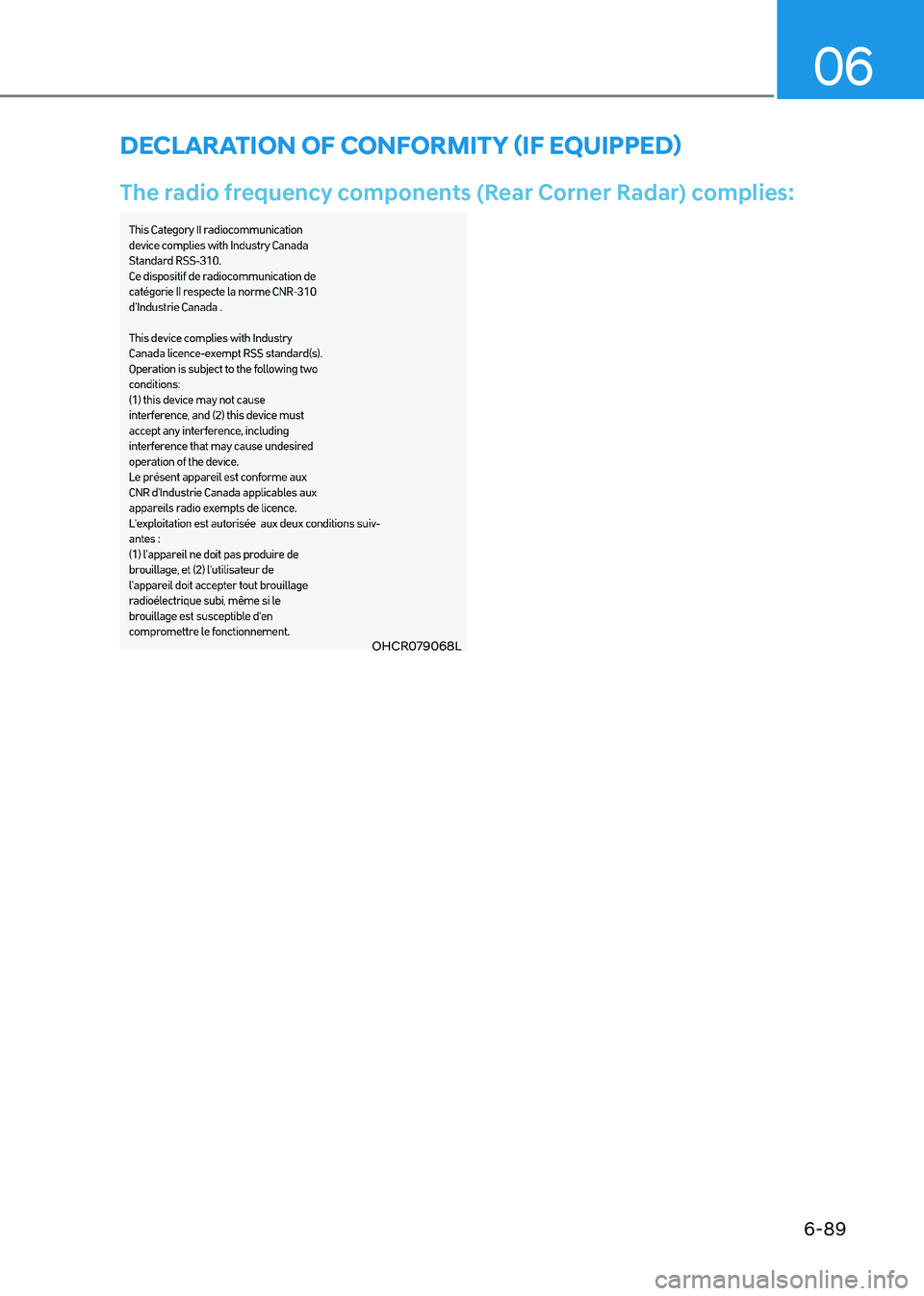
OHCR079068L
Declaration of conformity (if equippeD)
The radio frequency components (Rear Corner Radar) complies:
Page 412 of 555
06
6-125
CAUTION
Navigation-based Cruise Control
system may not function properly in the
following situations: • The navigation is not working
properly.
• The navigation is not updated.
• The real-time GPS or map
information provided has errors.
• The navigation is overloaded by
performing functions such as route
search, video playback, voice
recognition, etc. are performing
simultaneously.
• GPS signals are blocked in areas such as a tunnel.
• The driver goes off course or the
route to the destination is changed
or canceled by resetting the
navigation.
• The vehicle enters a service station
or rest area.
• A section of the highway’s shape has changed.
• Android Auto or Car Play is operating.
• The navigation cannot detect the
current vehicle position (ex: elevated
roads including overpass adjacent to
general roads or nearby roads exist
in a parallel way).
• The navigation is being updated while driving.
• The navigation is being reset while driving.
• The road is slippery due to bad
weather such as rain or snow. Information
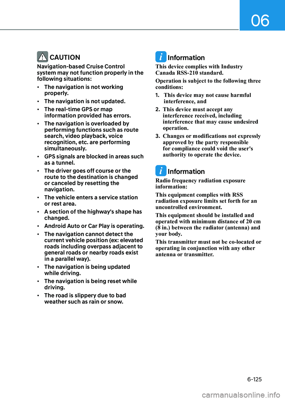
This device complies with Industry Canada RSS-210 standard.
Operation is subject to the following three conditions: 1. This device may not cause harmful
interference, and
2. This device must accept any
interference received, including
interference that may cause undesired operation.
3. Changes or modifications not expressly
approved by the party responsible
for compliance could void the user's authority to operate the device.
Information
Radio frequency radiation exposure information: This equipment complies with RSS
radiation exposure limits set forth for an
uncontrolled environment. This equipment should be installed and operated with minimum distance of 20 cm
(8 in.) between the radiator (antenna) and
your body.
This transmitter must not be co-located or
operating in conjunction with any other
antenna or transmitter.
Page 424 of 555
06
6-137
CAUTION
Highway Driving Assist system may
not function properly in the following
situations: • The navigation is not working
properly.
• The navigation is not updated.
• The real-time GPS or map
information provided has errors.
• The navigation is overloaded by
performing functions such as route
search, video playback, voice
recognition, etc. are performing
simultaneously.
• GPS signals are blocked in areas such as a tunnel.
• The driver goes off course or the
route to the destination is changed
or canceled by resetting the
navigation.
• The vehicle enters a service station
or rest area
• Android Auto or Car Play is operating.
• The navigation cannot detect the
current vehicle position (ex: elevated
roads including overpass adjacent to
general roads or nearby roads exist
in a parallel way).
• The navigation is being updated while driving.
• The navigation is being reset while driving.
• The road is slippery due to bad
weather such as rain or snow. Information
• For information's on vehicle to vehicle
distance control and the front radar,
refer to "Smart Cruise Control (SCC)"
in this chapter.
• For information's on steering control
and distance control and the front
camera, refer to "Lane Following Assist
(LFA)" in this chapter.
Information
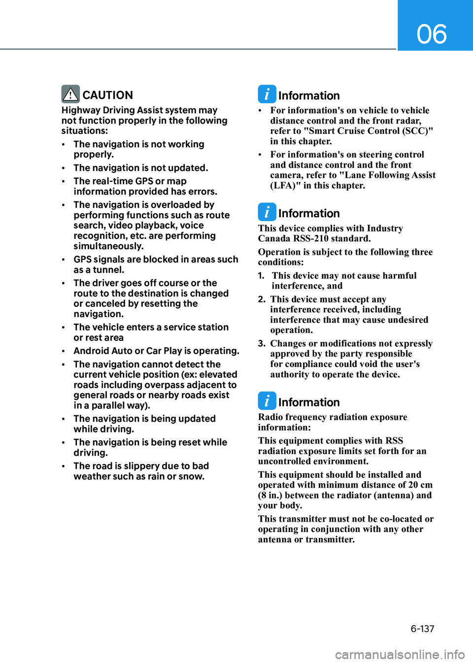
This device complies with Industry Canada RSS-210 standard.
Operation is subject to the following three conditions: 1. This device may not cause harmful
interference, and
2. This device must accept any
interference received, including
interference that may cause undesired operation.
3. Changes or modifications not expressly
approved by the party responsible
for compliance could void the user's authority to operate the device.
Information
Radio frequency radiation exposure information: This equipment complies with RSS
radiation exposure limits set forth for an
uncontrolled environment. This equipment should be installed and operated with minimum distance of 20 cm
(8 in.) between the radiator (antenna) and
your body.
This transmitter must not be co-located or
operating in conjunction with any other
antenna or transmitter.
Page 453 of 555
07
7-5
Jump starting procedure
1. Position the vehicles close enough
that the jumper cables will reach, but
do not allow the vehicles to touch.
2. Avoid fans or any moving parts in the engine compartment at all times, even
when the vehicles are turned off.
3. Turn off all electrical devices such as radios, lights, air conditioning, etc.
Put the vehicles in P (Park) and set
the parking brakes. Turn both vehicles
OFF.
ODN8A079022
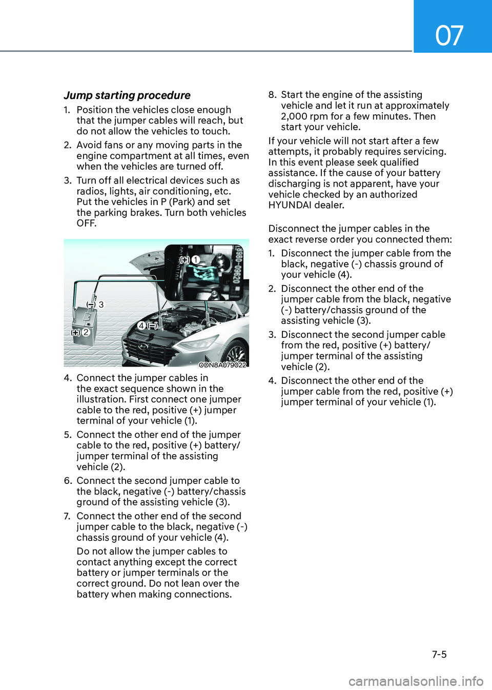
4. Connect the jumper cables in
the exact sequence shown in the
illustration. First connect one jumper
cable to the red, positive (+) jumper
terminal of your vehicle (1).
5. Connect the other end of the jumper cable to the red, positive (+) battery/
jumper terminal of the assisting
vehicle (2).
6. Connect the second jumper cable to the black, negative (-) battery/chassis
ground of the assisting vehicle (3).
7. Connect the other end of the second
jumper cable to the black, negative (-)
chassis ground of your vehicle (4).
Do not allow the jumper cables to
contact anything except the correct
battery or jumper terminals or the
correct ground. Do not lean over the
battery when making connections. 8. Start the engine of the assisting
vehicle and let it run at approximately
2,000 rpm for a few minutes. Then
start your vehicle.
If your vehicle will not start after a few
attempts, it probably requires servicing.
In this event please seek qualified
assistance. If the cause of your battery
discharging is not apparent, have your
vehicle checked by an authorized
HYUNDAI dealer. Disconnect the jumper cables in the
exact reverse order you connected them:
1. Disconnect the jumper cable from the black, negative (-) chassis ground of
your vehicle (4).
2. Disconnect the other end of the jumper cable from the black, negative
(-) battery/chassis ground of the
assisting vehicle (3).
3. Disconnect the second jumper cable from the red, positive (+) battery/
jumper terminal of the assisting
vehicle (2).
4. Disconnect the other end of the
jumper cable from the red, positive (+)
jumper terminal of your vehicle (1).
Page 459 of 555

07
7-11
TPMS Malfunction
Indicator
The TPMS Malfunction Indicator
will illuminate after it blinks for
approximately one minute when there
is a problem with the Tire Pressure
Monitoring System.
Have the system checked by an
authorized HYUNDAI dealer as soon as possible.
NOTICE
If there is a malfunction with the
TPMS, the individual tire pressures
in the cluster LCD display will not be
available. Have the system checked by
an authorized HYUNDAI dealer as soon as possible.
NOTICE
The TPMS Malfunction Indicator may
illuminate after blinking for one minute
if the vehicle is near electric power
supply cables or radio transmitters
such as police stations, government
and public offices, broadcasting
stations, military installations, airports,
transmitting towers, etc.
Additionally, the TPMS Malfunction
Indicator may illuminate if snow chains
are used or electronic devices such as
computers, chargers, remote starters,
navigation, etc. This may interfere with
normal operation of the TPMS.
Changing a Tire with TPMS
If you have a flat tire, the Low Tire
Pressure and LCD position indicator will
come on. Have the flat tire repaired by an
authorized HYUNDAI dealer as soon as
possible or replace the flat tire with the
spare tire. (if equipped)
CAUTION
It is recommended that you do not use a
puncture-repairing agent not approved
by HYUNDAI dealer to repair and/or
inflate a low pressure tire. Tire sealant
not approved by HYUNDAI dealer may
damage the tire pressure sensor.
The spare tire does not come with a
tire pressure monitoring sensor. When
the low pressure tire or the flat tire is
replaced with the spare tire, the Low
Tire Pressure LCD position indicator will
remain on. Also, the TPMS Malfunction
Indicator will illuminate after blinking
for one minute if the vehicle is driven
at speed above 25 km/h (15.5 mph) for
approximately 20 minutes. Once the
original tire equipped.
Once the original tire equipped with
a tire pressure monitoring sensor is
reinflated to the recommended pressure
and reinstalled on the vehicle, the Low
Tire Pressure LCD position indicator and
TPMS Malfunction Indicator will go off
within a few minutes of driving.
If the indicators do not disappear after a
few minutes, please visit an authorized
HYUNDAI dealer.
Page 546 of 555
Index
I-4
Climate Control Air Filter .................................................................................... 8-33
Filter Inspection ................................................................................................ 8-33
Filter Replacement ........................................................................................... 8-33
D Declaration of Conformity ................................................................................... 6-89
The Radio Frequency Components (Rear Corner Radar) Complies: ...............6-89
Dimensions .......................................................................................................... 2-10
Door Locks .......................................................................................................... 5-16
Automatic Door Lock and Unlock Features ....................................................5-20
Child-Protector Rear Door Locks .................................................................... 5-20
Operating Door Locks from Inside the Vehicle................................................ 5-17
Operating Door Locks from Outside the Vehicle .............................................5-16
Rear Occupant Alert (ROA) System ................................................................ 5-21
Vehicle Auto-Shut Off Function ....................................................................... 5-22
Drive Mode Integrated Control System ..............................................................6-45
Drive Mode ...................................................................................................... 6-45
Vehicle Characteristic ....................................................................................... 6-49
Driver Attention Warning (DAW) ....................................................................... 6-96
Leading Vehicle Departure Alert ................................................................... 6-101
Resetting the System ........................................................................................ 6-98
System Malfunction ......................................................................................... 6-99
System Setting and Operation .......................................................................... 6-96
System Standby ................................................................................................ 6-99
Driver position memory system .......................................................................... 5-24
Easy Access Function ....................................................................................... 5-26
Recalling Positions from Memory ................................................................... 5-25
Resetting the Driver’s Seat Memory System ...................................................5-25
Storing Positions into Memory ....................................................................... 5-24
Dual Clutch Transmission .................................................................................. 6-20
Dual Clutch Transmission Operation ............................................................... 6-20
Good Driving Practices ................................................................................... 6-29
LCD Display Message (Button Type) ..............................................................6-27
Parking ............................................................................................................. 6-27