2023 FORD MAVERICK ECU
[x] Cancel search: ECUPage 319 of 556
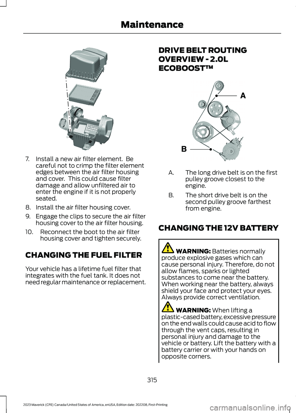
7.Install a new air filter element. Becareful not to crimp the filter elementedges between the air filter housingand cover. This could cause filterdamage and allow unfiltered air toenter the engine if it is not properlyseated.
8.Install the air filter housing cover.
9.Engage the clips to secure the air filterhousing cover to the air filter housing.
10.Reconnect the boot to the air filterhousing cover and tighten securely.
CHANGING THE FUEL FILTER
Your vehicle has a lifetime fuel filter thatintegrates with the fuel tank. It does notneed regular maintenance or replacement.
DRIVE BELT ROUTING
OVERVIEW - 2.0L
ECOBOOST™
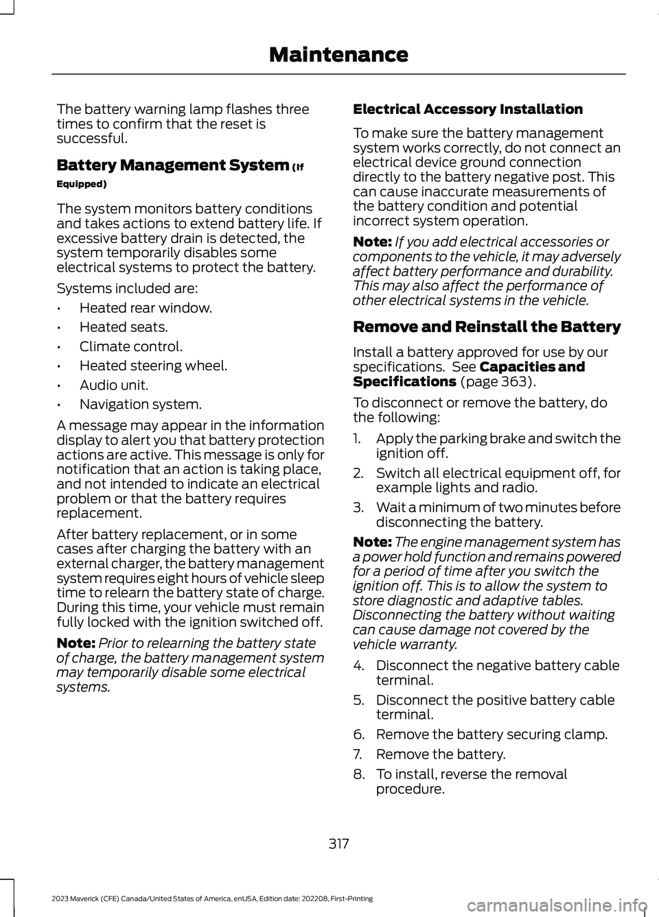
The long drive belt is on the firstpulley groove closest to theengine.
A.
The short drive belt is on thesecond pulley groove farthestfrom engine.
B.
CHANGING THE 12V BATTERY
WARNING: Batteries normallyproduce explosive gases which cancause personal injury. Therefore, do notallow flames, sparks or lightedsubstances to come near the battery.When working near the battery, alwaysshield your face and protect your eyes.Always provide correct ventilation.
WARNING: When lifting aplastic-cased battery, excessive pressureon the end walls could cause acid to flowthrough the vent caps, resulting inpersonal injury and damage to thevehicle or battery. Lift the battery with abattery carrier or with your hands onopposite corners.
315
2023 Maverick (CFE) Canada/United States of America, enUSA, Edition date: 202208, First-PrintingMaintenanceE299074 E161383
Page 321 of 556
The battery warning lamp flashes threetimes to confirm that the reset issuccessful.
Battery Management System (If
Equipped)
The system monitors battery conditionsand takes actions to extend battery life. Ifexcessive battery drain is detected, thesystem temporarily disables someelectrical systems to protect the battery.
Systems included are:
•Heated rear window.
•Heated seats.
•Climate control.
•Heated steering wheel.
•Audio unit.
•Navigation system.
A message may appear in the informationdisplay to alert you that battery protectionactions are active. This message is only fornotification that an action is taking place,and not intended to indicate an electricalproblem or that the battery requiresreplacement.
After battery replacement, or in somecases after charging the battery with anexternal charger, the battery managementsystem requires eight hours of vehicle sleeptime to relearn the battery state of charge.During this time, your vehicle must remainfully locked with the ignition switched off.
Note:Prior to relearning the battery stateof charge, the battery management systemmay temporarily disable some electricalsystems.
Electrical Accessory Installation
To make sure the battery managementsystem works correctly, do not connect anelectrical device ground connectiondirectly to the battery negative post. Thiscan cause inaccurate measurements ofthe battery condition and potentialincorrect system operation.
Note:If you add electrical accessories orcomponents to the vehicle, it may adverselyaffect battery performance and durability.This may also affect the performance ofother electrical systems in the vehicle.
Remove and Reinstall the Battery
Install a battery approved for use by ourspecifications. See Capacities andSpecifications (page 363).
To disconnect or remove the battery, dothe following:
1.Apply the parking brake and switch theignition off.
2.Switch all electrical equipment off, forexample lights and radio.
3.Wait a minimum of two minutes beforedisconnecting the battery.
Note:The engine management system hasa power hold function and remains poweredfor a period of time after you switch theignition off. This is to allow the system tostore diagnostic and adaptive tables.Disconnecting the battery without waitingcan cause damage not covered by thevehicle warranty.
4.Disconnect the negative battery cableterminal.
5.Disconnect the positive battery cableterminal.
6.Remove the battery securing clamp.
7.Remove the battery.
8.To install, reverse the removalprocedure.
317
2023 Maverick (CFE) Canada/United States of America, enUSA, Edition date: 202208, First-PrintingMaintenance
Page 324 of 556

Electrical Accessory Installation
To make sure the battery managementsystem works correctly, do not connect anelectrical device ground connectiondirectly to the battery negative post. Thiscan cause inaccurate measurements ofthe battery condition and potentialincorrect system operation.
Note:If you add electrical accessories orcomponents to the vehicle, it may adverselyaffect battery performance and durability.This may also affect the performance ofother electrical systems in the vehicle.
Remove and Reinstall the Battery
Install a battery approved for use by ourspecifications. See Capacities andSpecifications (page 363).
To disconnect or remove the battery, dothe following:
1.Apply the parking brake and switch theignition off.
2.Switch all electrical equipment off, forexample lights and radio.
3.Wait a minimum of two minutes beforedisconnecting the battery.
Note:The engine management system hasa power hold function and remains poweredfor a period of time after you switch theignition off. This is to allow the system tostore diagnostic and adaptive tables.Disconnecting the battery without waitingcan cause damage not covered by thevehicle warranty.
4.Disconnect the negative battery cableterminal.
5.Disconnect the positive battery cableterminal.
6.Remove the battery securing clamp.
7.Remove the battery.
8.To install, reverse the removalprocedure.
Note:Before reconnecting the battery,make sure the ignition remains switched off.
Note:Make sure to fully tighten the batterycables.
If you disconnect or replace the vehiclebattery, you must reset the followingfeatures:
•Window bounce-back. See What IsWindow Bounce-Back (page 100).
•Clock Settings.
•Pre-set radio stations.
Battery Disposal
Make sure that you dispose ofold batteries in anenvironmentally friendly way.Seek advice from your local authorityabout recycling old batteries.
ADJUSTING THE HEADLAMPS
Vertical Aim Adjustment
The headlamps on your vehicle areproperly aimed at the assembly plant. Ifyour vehicle has been in an accident, havethe alignment of your headlamps checkedas soon as possible.
8 ft (2.4 m)A
Center height of lamp to groundB
320
2023 Maverick (CFE) Canada/United States of America, enUSA, Edition date: 202208, First-PrintingMaintenanceE107998 E142592
Page 349 of 556
Compliance Certification label, or theTire Label on the B-Pillar or the edge ofthe driver door. Failure to follow thisinstruction could result in loss of vehiclecontrol, vehicle rollover, or personal injuryor death.
The tires on your vehicle could haveall-weather treads to provide traction inrain and snow. In some climates you willneed to use snow tires and chains on yourvehicle in emergency situations or ifrequired by law.
Note:The suspension insulation andbumpers will help prevent vehicle damage.Do not remove these components from yourvehicle when using snow tires and chains.
Note:Driving too fast for road conditionscreates the possibility of loss of vehiclecontrol. Driving at very high speeds forextended periods of time may result indamage to vehicle components.
Follow these guidelines when using snowtires and chains:
•Chains may damage aluminum wheels.
•Use ultra low profile cables, 10 mm orless in dimension as measured on thesidewall of your tire, only with225/65R17, or 225/60R18 all seasontires.
•Do not use snow chains or cables with235/65R17.
•Not all S-class snow chains or cablesmeet these restrictions. Chains of thissize restriction will include a tensioningdevice.
•Purchase chains or cables from amanufacturer that clearly labels bodyto tire dimension restrictions. The snowchains or cables must be mounted inpairs on the front tires only.
•When driving with snow chains do notexceed 30 mph (50 km/h) or themaximum speed recommended by thechain manufacturer, whichever is less.
•Install cables securely, verifying thatthe cables do not touch any wiring orbrake lines.
•Drive cautiously. If you hear the cablesrub or bang against the vehicle, stopand retighten them. If this does notwork, remove the cables to preventvehicle damage.
•Remove the tire chains when they areno longer needed. Do not use tirechains on dry roads.
If you have any questions regarding snowchains or cables, please contact yourauthorized dealer.
345
2023 Maverick (CFE) Canada/United States of America, enUSA, Edition date: 202208, First-PrintingWheel and Tire Information
Page 358 of 556

CHANGING A FLAT TIRE
Have a flat serviced by an authorizeddealer to prevent damage to the systemsensors. See Tire Pressure MonitoringSystem Precautions (page 351).Replacethe spare tire with a road tire as soon aspossible. During repairing or replacing theflat tire, have the authorized dealer inspectthe system sensor for damage.
If you get a flat tire when driving, do notapply the brake heavily. Instead, graduallydecrease your speed. Hold the steeringwheel firmly and slowly move to a safeplace on the side of the road.
Note:The use of tire sealant may damageyour tire pressure monitoring system andshould only be used in roadsideemergencies.
Note:The tire pressure monitoring systemindicator light illuminates when the sparetire is in use. To restore the full function ofthe monitoring system, all road wheelsequipped with tire pressure monitoringsensors must be mounted on this vehicle.
WARNING: Never place anythingbetween the vehicle jack and the ground.
WARNING: Never place anythingbetween the vehicle jack and yourvehicle.
WARNING: To help prevent yourvehicle from moving when changing awheel, shift the transmission into park(P), set the parking brake and use anappropriate block or wheel chock tosecure the wheel diagonally opposite tothe wheel being changed. For example,when changing the front left wheel,place an appropriate block or wheelchock on the right rear wheel.
WARNING: It is recommended thatthe wheels of the vehicle be chocked,and that no person should remain in avehicle that is being jacked.
WARNING: Only use the jackprovided as original equipment with yourvehicle.
WARNING: The jack supplied withthis vehicle is only intended for changinga flat tire in an emergency. Do notattempt to do any other work on yourvehicle when it is supported by the jack,as your vehicle could slip off the jack.Failure to follow this instruction couldresult in personal injury or death.
WARNING: The jack should beused on level firm ground whereverpossible.
WARNING: Only use the specifiedjacking points. If you use any otherlocations you could damage vehiclecomponents, such as brake lines.
WARNING: Switch the ignition offand apply the parking brake. If yourvehicle has a manual transmission, shiftinto first or reverse gear. If your vehiclehas an automatic transmission, shift intopark (P).
WARNING: Do not attempt tochange a tire on the side of the vehicleclose to moving traffic. Pull far enoughoff the road to not obstruct the flow oftraffic and avoid the danger of being hitwhen operating the jack or changing thewheel.
WARNING: No person should placeany portion of their body under a vehiclethat is supported by a jack.
354
2023 Maverick (CFE) Canada/United States of America, enUSA, Edition date: 202208, First-PrintingChanging a Road Wheel
Page 363 of 556
8.Stow the flat tire. See the Stowing theFlat or Spare Tire.
9.Stow the vehicle jack and lug wrench.Make sure the jack is securely fastenedbefore you drive. See Stowing theVehicle Jack and Tool Bag.
10.Unblock the wheels.
Stowing the Road Wheel
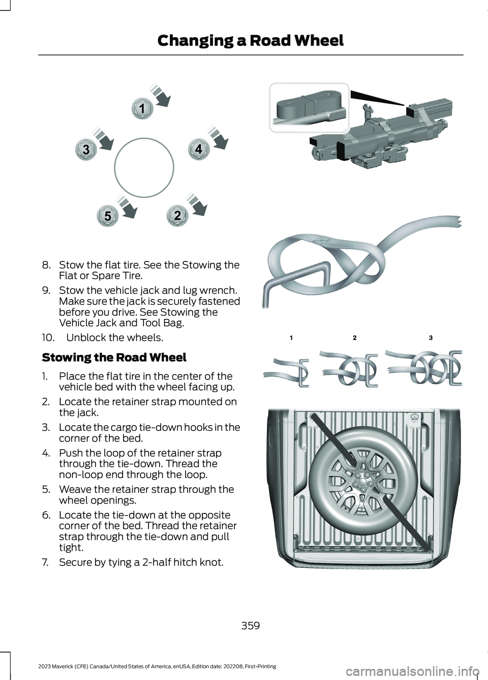
1.Place the flat tire in the center of thevehicle bed with the wheel facing up.
2.Locate the retainer strap mounted onthe jack.
3.Locate the cargo tie-down hooks in thecorner of the bed.
4.Push the loop of the retainer strapthrough the tie-down. Thread thenon-loop end through the loop.
5.Weave the retainer strap through thewheel openings.
6.Locate the tie-down at the oppositecorner of the bed. Thread the retainerstrap through the tie-down and pulltight.
7.Secure by tying a 2-half hitch knot.
359
2023 Maverick (CFE) Canada/United States of America, enUSA, Edition date: 202208, First-PrintingChanging a Road Wheel12345E306781 E355266 E142906 E143746 E355267
Page 364 of 556
Stowing the Spare Tire
Note:Failure to follow the spare tirestowage instructions could result in failureof the cable or loss of the spare tire.
1.Lay the tire on the ground with thevalve stem facing down.
2.Slide the wheel partially under thevehicle and install the retainer throughthe wheel center. Pull on the cable toalign the components at the end of thecable.
3.Turn the jack handle clockwise untilthe tire is raised to its stowed positionunderneath the vehicle. The effort toturn the jack handle increasessignificantly and the spare tire carrierratchets or slips when the tire is raisedto the maximum tightness. Tighten tothe point where the ratchet or slipoccurs, a minimum of three times asindicated by an audible click each time.The spare tire carrier does not allowyou to overtighten. If the spare tirecarrier ratchets or slips with little effort,contact your authorized dealer.
4.Check that the tire lies flat against theframe and is properly tightened. Try topush or pull, then turn the tire to besure it does not move. Loosen andretighten, if necessary. Failure toproperly stow the spare tire couldresult in failure of the winch cable andloss of the tire.
5.Repeat this tightness check procedurewhen servicing the spare tire pressure,every six months, as per your scheduledmaintenance information, or at anytime that the spare tire is disturbedthrough service of other components.
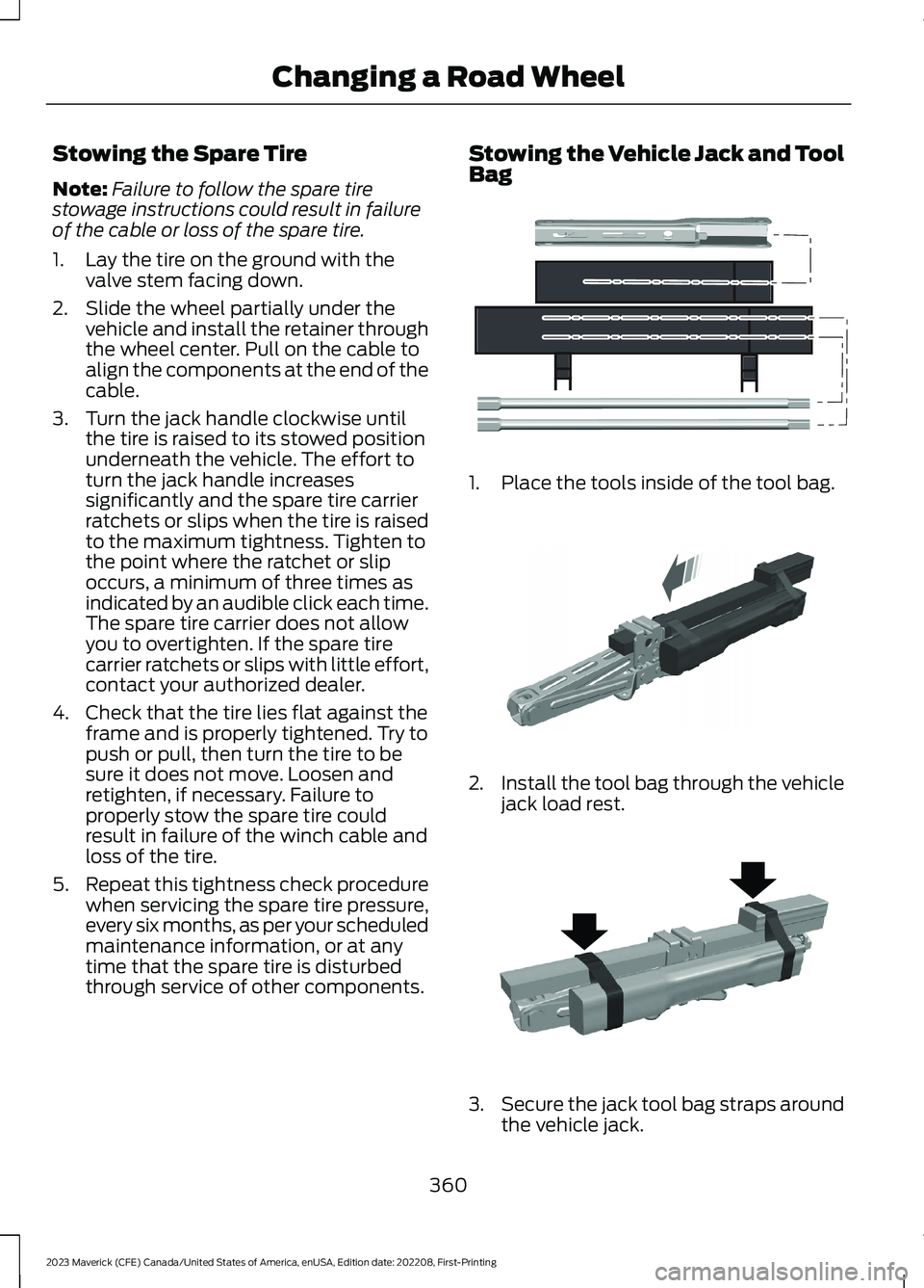
Stowing the Vehicle Jack and ToolBag
1.Place the tools inside of the tool bag.
2.Install the tool bag through the vehiclejack load rest.
3.Secure the jack tool bag straps aroundthe vehicle jack.
360
2023 Maverick (CFE) Canada/United States of America, enUSA, Edition date: 202208, First-PrintingChanging a Road WheelE352149 E352034 E352022
Page 365 of 556
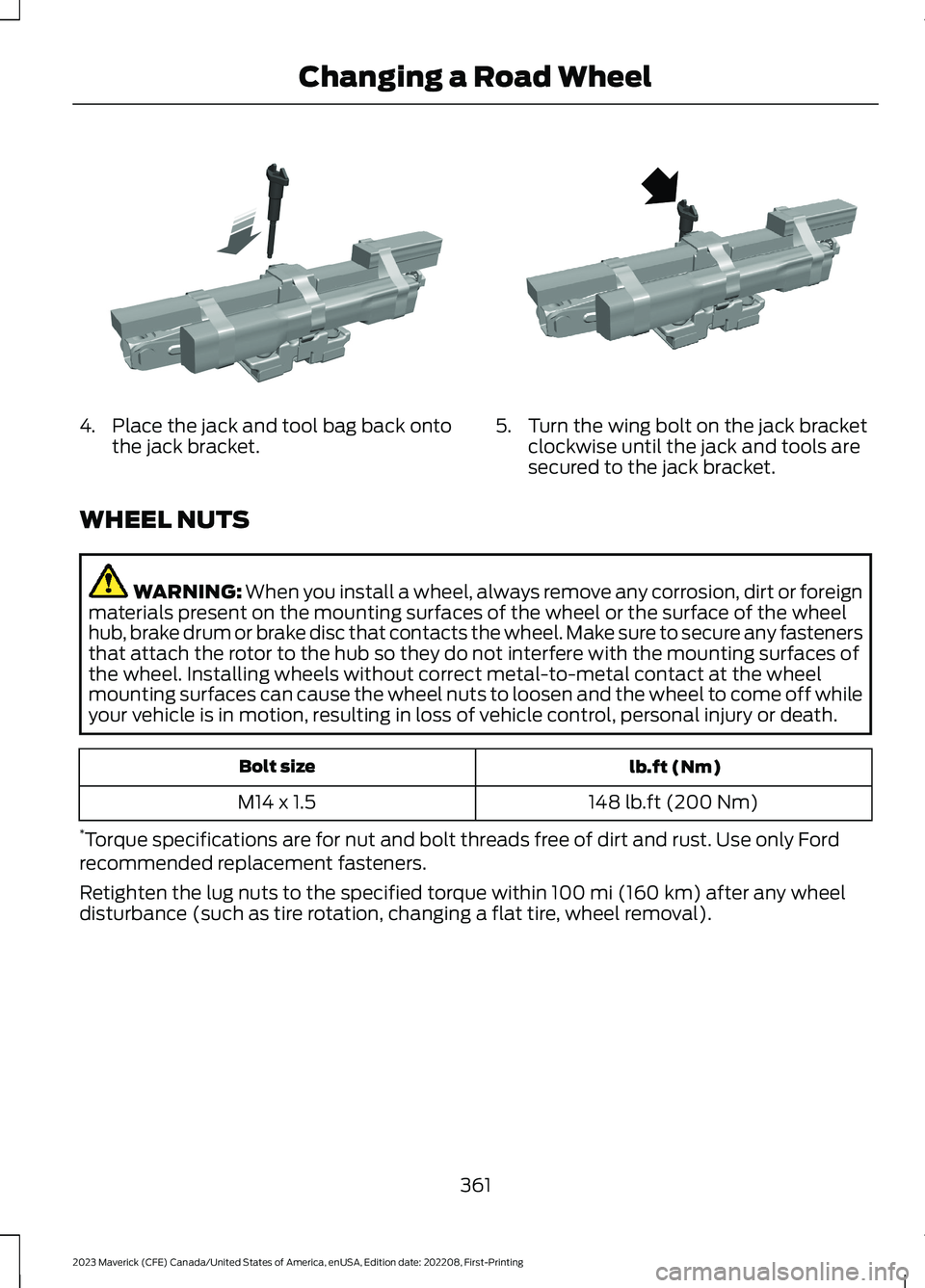
4.Place the jack and tool bag back ontothe jack bracket.5.Turn the wing bolt on the jack bracketclockwise until the jack and tools aresecured to the jack bracket.
WHEEL NUTS
WARNING: When you install a wheel, always remove any corrosion, dirt or foreignmaterials present on the mounting surfaces of the wheel or the surface of the wheelhub, brake drum or brake disc that contacts the wheel. Make sure to secure any fastenersthat attach the rotor to the hub so they do not interfere with the mounting surfaces ofthe wheel. Installing wheels without correct metal-to-metal contact at the wheelmounting surfaces can cause the wheel nuts to loosen and the wheel to come off whileyour vehicle is in motion, resulting in loss of vehicle control, personal injury or death.
lb.ft (Nm)Bolt size
148 lb.ft (200 Nm)M14 x 1.5
*Torque specifications are for nut and bolt threads free of dirt and rust. Use only Fordrecommended replacement fasteners.
Retighten the lug nuts to the specified torque within 100 mi (160 km) after any wheeldisturbance (such as tire rotation, changing a flat tire, wheel removal).
361
2023 Maverick (CFE) Canada/United States of America, enUSA, Edition date: 202208, First-PrintingChanging a Road WheelE352027 E352026