2023 FORD F650/750 alternator
[x] Cancel search: alternatorPage 205 of 378

Protected Component Rating Item
Blower motor control.
Upfitter - frame. 20 A 3
Starter motor. 30 A 4
Not used. — 5
Upfitter relay 4. 20 A 6
Not used. — 8
Not used. — 10
Not used. — 12
Run/start spare. 10 A 13
Adaptive cruise control. 10 A 14
Blower motor relay. 10 A 15
Air dryer. 20 A 16
Powertrain control module
- ignition status run power. 10 A 17
Glow plug control module -
ignition status run power
(diesel).
Anti-lock brake system run/
start. 10 A 18
Transmission control
module. 10 A 19
Ignition status run power
(diesel).
Windshield wiper motor. 30 A 20
Not used. — 21
Not used. — 22
Alternator 2 (dual alternator
only). 10 A 23
Body control module run
power 2 bus. 40 A 24
201
Fuses
Page 206 of 378

Protected Component Rating Item
Body control module run
power 1 bus. 50 A 25
Not used. — 26
Upfitter battery feed. 20 A 27
Not used. — 28
Alternator 1 A-Line. 10 A 29
Not used. — 30
Hydromax pump. 60 A 31
Powertrain control module. 20 A 32
Canister vent solenoid (gas). 20 A 33
Canister purge solenoid
(gas).
Variable cam timing actu-
ator 11 (gas).
Heated exhaust gas oxygen
sensor (gas).
Urea tank power (diesel).
Exhaust gas recirculation
cool bypass valve (diesel).
A/C clutch relay. 10 A 34
Customer access vehicle
power 3 feed.
Variable oil pump (diesel).
Cooling fan (diesel).
Fan clutch (gas).
Exhaust brake switch.
Variable oil pressure control
(gas)
Coil on plug (gas) 20 A 35
Urea tank (diesel).
Glow plug controller
(diesel).
Nitrogen oxide sensor
control module (diesel).
Particulate matter sensor
(diesel).
Fuel volume control value
(diesel). 10 A 36
202
Fuses
Page 215 of 378

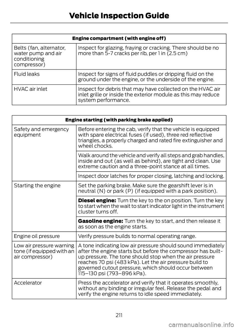
Engine compartment (with engine off)
Inspect for glazing, fraying or cracking. There should be no
more than 5-7 cracks per rib, per 1 in (2.5 cm) Belts (fan, alternator,
water pump and air
conditioning
compressor)
Inspect for signs of fluid puddles or dripping fluid on the
ground under the engine, or the underside of the engine. Fluid leaks
Inspect for debris that may have collected on the HVAC air
inlet grille or inside the exterior module as this may reduce
system performance. HVAC air inlet
Engine starting (with parking brake applied)
Before entering the cab, verify that the vehicle is equipped
with spare electrical fuses (if used), three red reflective
triangles, a properly charged and rated fire extinguisher and
wheel chocks. Safety and emergency
equipment
Walk around the vehicle and verify all steps and grab handles,
inside and out (as well as behind), are tight and clean. Use
extreme caution and a three-point stance at all times.
Inspect door latches for proper closing, latching and locking.
Set the parking brake. Make sure the gearshift lever is in
neutral (N) or park (P) (if equipped with a park position). Starting the engine
Diesel engine: Turn the key to the on position. Turn the key
to start when the wait to start indicator light in the instrument
cluster turns off.
Gasoline engine: Turn the key to start, and then release it
as soon as the engine starts.
Verify pressure builds to normal operating range. Engine oil pressure
A tone indicating low air pressure should sound immediately
after the engine starts but before the compressor has built-
up pressure. The tone should stop when the air pressure
reaches 70 psi (483 kPa). Let the air pressure build to
governed cutout pressure, which should occur between
115–130 psi (793–896 kPa). Low air pressure warning
tone (if equipped with an
air compressor)
Press the accelerator and verify that it operates smoothly,
without any binding or irregular feel. Release the pedal and
verify the engine returns to idle speed immediately. Accelerator
211
Vehicle Inspection Guide
Page 216 of 378

Engine starting (with parking brake applied)
Check the gauge (diesel engine) or indicator light (gasoline
engine) to verify the alternator is charging. Voltmeter
Inspect for excessive free play in the steering linkages. The
steering wheel should have less than 2 in (5 cm) of free play
at its rim. Steering linkage free play
Verify the parking brake holds the vehicle by gently trying to
pull forward with the parking brake applied. Parking brake
Verify operation using the following procedure. Chock the
wheels, if necessary. Push in the parking brake and, on
tractors, push in the tractor parking brake knob: Air brakes
1. Verify the air compressor or governor cutout pressure is
approximately 120 psi (827 kPa).
2. Turn off the engine, and then turn the key back to the on
position (without starting the engine).
3. Without the brake pedal applied, note the air pressure drop
for one minute. It should be less than 2 psi (14 kPa) for single
vehicles and 3 psi (21 kPa) for combination vehicles.
4. Press and hold the brake pedal with 90 psi (621 kPa) or
more. Make sure there is no more than a 3 psi (21 kPa) per
minute leak for single vehicles and a 4 psi (28 kPa) minute
leak for combination vehicles.
5. Pump the brake pedal to deplete the system of air pressure.
The warning light and tone should turn on at 57 psi (393 kPa).
6. Pump the brake pedal and make sure the parking brake
and trailer parking brake knobs pop out at 20 psi (138 kPa)
or higher.
Verify that the fluid level is in the proper operating range. See
Automatic Transmission Fluid Check (page 242). Automatic transmission
fluid
Front of vehicle
Verify all exterior lights illuminate and are clean. Lights
Check headlights function on high and low beam.
Verify reflectors are clean, unbroken and of proper color (red
on rear, amber elsewhere).
212
Vehicle Inspection Guide
Page 258 of 378

2. Reconnect the fuel lines.
3. Switch the ignition on for 30 seconds
and then switch the ignition off.
Repeat this operation six times in a row
to purge any trapped air from the fuel
system.
ELECTRICAL SYSTEM
INSPECTION
Periodically inspect electrical connectors
on the outside of the cab and on the engine
and frame for corrosion and tightness.
Exposed terminals, such as the fuel sender,
cranking motor, alternator and
feed-through studs, should be cleaned and
re-coated with a lubricant sealing grease
such as Motorcraft Silicone Brake Caliper
Grease and Dielectric Compound XG-3, or
equivalent. This should include the ground
cable connector for batteries, engine and
cab as well as the jump-starting stud.
Accessory Feed Connections
Vehicle electrical systems are complex and
often include powertrain components,
such as engine and transmission controls,
instrument panels and ABS. While most
systems operate on battery voltage (12
volts), some systems can be as high as 90
volts or as low as five volts. See the
Electrical Circuit Diagram Manuals,
available from your vehicle’s manufacturer,
to make sure that any extra body lights and
accessory connections to circuits are both
appropriate and not overloaded. Do not
make modifications to any vehicle control
system without first contacting an
authorized dealer.
AIR INDUCTION SYSTEM
INSPECTION
WARNING: When performing
maintenance to any turbocharged engine
with engine air inlet piping disconnected,
keep loose clothing, jewelry and long hair
away from the engine air inlet piping. A
turbocharger compressor air inlet
protective shield should be installed over
the turbocharger air inlet to reduce the
risk of personal injury or death.
Perform a complete inspection of the air
induction system annually.
In areas where road salt is used,
disassemble the joints of each aluminum
component and inspect for salt build-up
and presence of chlorine that can cause
aluminum particles to flake off and enter
the engine combustion chambers. If
evidence of corrosion is found (usually at
the pipe connections), use a wire brush to
clean the inside of the pipes and inside the
rubber hoses.
If pitting is evident at the joint ends of the
intake pipes, use Motorcraft Silicone
Gasket and Sealant TA-30 to seal the
joints. Make sure no excess material, which
can pull into the engine, is on the inside of
the pipes. If the service condition of the
pipes, hoses or clamps is questionable,
replace the defective part(s).
Make sure to clean all dust and debris out
of the pipes and couplings with a clean,
damp rag before reassembly.
Chassis-mounted Charge Air
Cooler
Visually inspect the core assembly for
debris and clogging of external fins with
the engine off.
254
Maintenance
Page 292 of 378

ENGINE SPECIFICATIONS - 6.7L DIESEL
6.7L V8 Diesel Engine Engine
406 in³ (6,651 cm³) Displacement.
Ultra Low Sulfur Diesel up to B20 Required fuel.
1-3-7-2-6-5-4-8 Firing order.
15.8:1 Compression ratio.
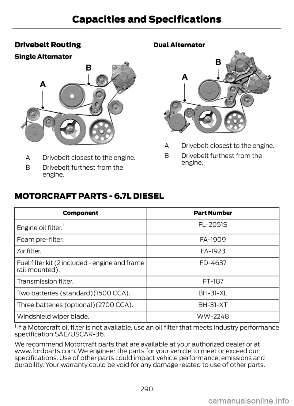
Drivebelt Routing
Single Alternator
E224819
Single Alternator With Air Brake
Compressor
E224825
Drivebelt closest to the engine. A
Drivebelt furthest from the
engine. B
288
Capacities and Specifications
Page 293 of 378

Dual Alternator
E224820
Dual Alternator With Air Brake
Compressor
E224826
Drivebelt closest to the engine. A
Drivebelt furthest from the
engine. B
Note:The belt routings show vehicles with
air conditioning. When vehicles do not have
air conditioning, an idler pulley is in place of
the A/C compressor.
ENGINE SPECIFICATIONS - 7.3L
7.3L V8 Engine Engine
445 in³ (7,293 cm³) Displacement.
Minimum 87 octane Required fuel.
1-5-4-8-6-3-7-2 Firing order.
Coil near spark plug with spark plug wire Ignition system.
0.049 in (1.25 mm) - 0.053 in (1.35 mm) Spark plug gap.
10.5:1 Compression ratio.
289
Capacities and Specifications
Page 294 of 378

Drivebelt Routing
Single Alternator
E3305075E3305075
Drivebelt closest to the engine. A
Drivebelt furthest from the
engine. BDual Alternator
E2988579E2988579
Drivebelt closest to the engine. A
Drivebelt furthest from the
engine. B
MOTORCRAFT PARTS - 6.7L DIESEL
Part Number Component
FL-2051S
Engine oil filter.1
FA-1909 Foam pre-filter.
FA-1923 Air filter.
FD-4637 Fuel filter kit (2 included - engine and frame
rail mounted).
FT-187 Transmission filter.
BH-31-XL Two batteries (standard)(1500 CCA).
BH-31-XT Three batteries (optional)(2700 CCA).
WW-2248 Windshield wiper blade.
1 If a Motorcraft oil filter is not available, use an oil filter that meets industry performance
specification SAE/USCAR-36.
We recommend Motorcraft parts that are available at your authorized dealer or at
www.fordparts.com. We engineer the parts for your vehicle to meet or exceed our
specifications. Use of other parts could impact vehicle performance, emissions and
durability. Your warranty could be void for any damage related to use of other parts.
290
Capacities and Specifications