2023 FORD F650/750 fuel
[x] Cancel search: fuelPage 195 of 378

4
2
1
3
E142664
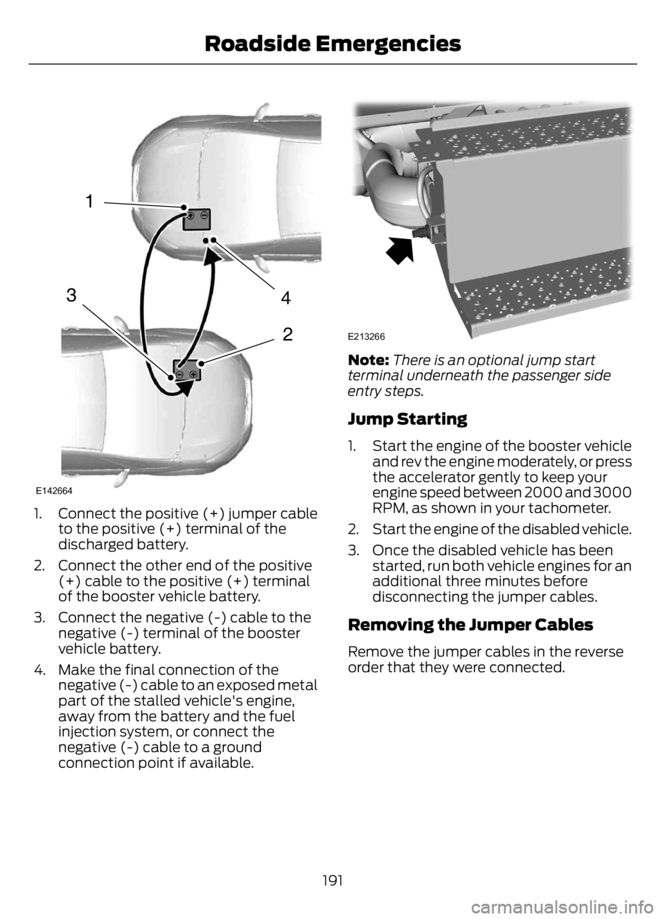
1. Connect the positive (+) jumper cable
to the positive (+) terminal of the
discharged battery.
2. Connect the other end of the positive
(+) cable to the positive (+) terminal
of the booster vehicle battery.
3. Connect the negative (-) cable to the
negative (-) terminal of the booster
vehicle battery.
4. Make the final connection of the
negative (-) cable to an exposed metal
part of the stalled vehicle's engine,
away from the battery and the fuel
injection system, or connect the
negative (-) cable to a ground
connection point if available.
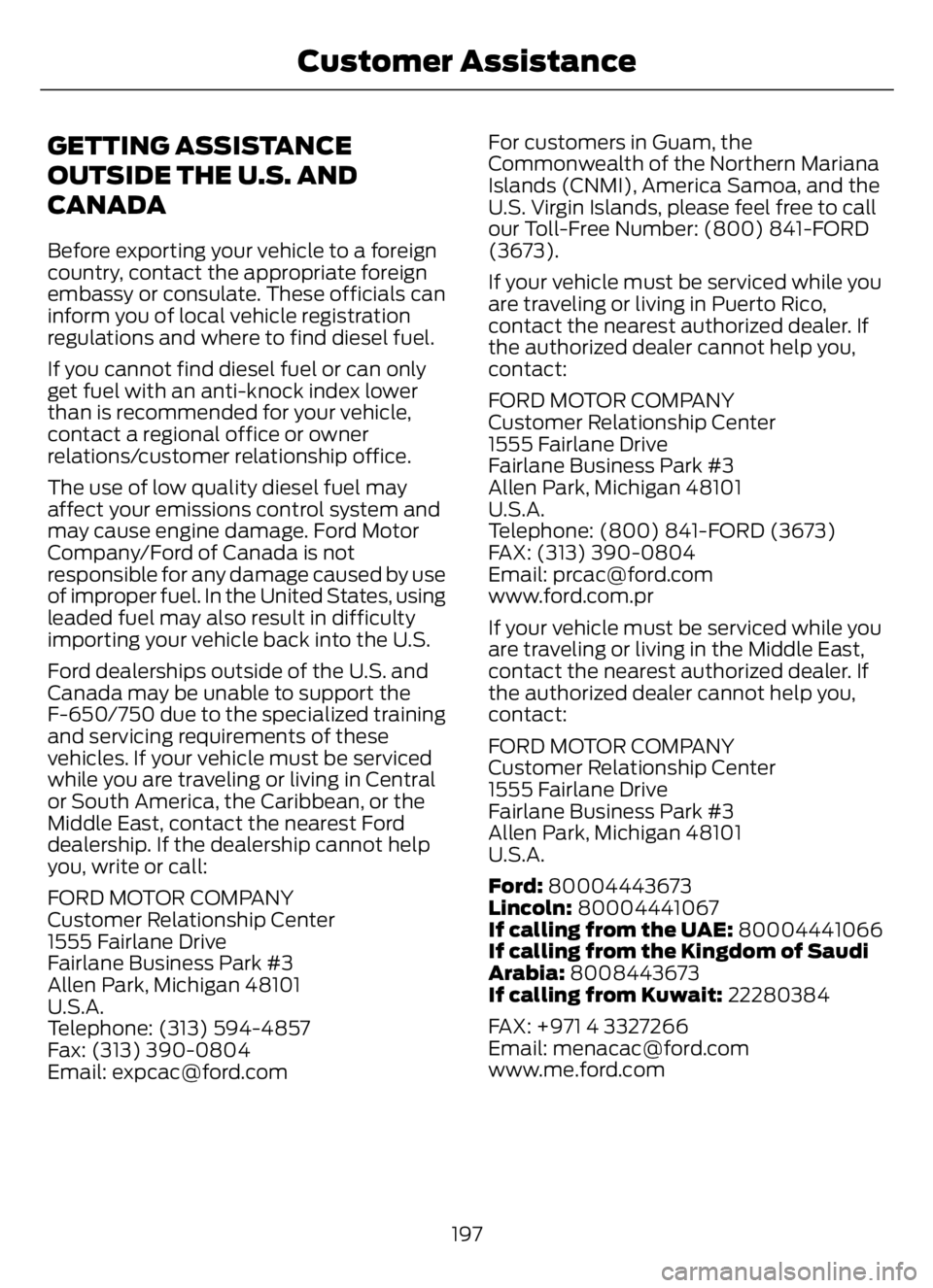
E213266
Note:There is an optional jump start
terminal underneath the passenger side
entry steps.
Jump Starting
1. Start the engine of the booster vehicle
and rev the engine moderately, or press
the accelerator gently to keep your
engine speed between 2000 and 3000
RPM, as shown in your tachometer.
2. Start the engine of the disabled vehicle.
3. Once the disabled vehicle has been
started, run both vehicle engines for an
additional three minutes before
disconnecting the jumper cables.
Removing the Jumper Cables
Remove the jumper cables in the reverse
order that they were connected.
191
Roadside Emergencies
Page 201 of 378

GETTING ASSISTANCE
OUTSIDE THE U.S. AND
CANADA
Before exporting your vehicle to a foreign
country, contact the appropriate foreign
embassy or consulate. These officials can
inform you of local vehicle registration
regulations and where to find diesel fuel.
If you cannot find diesel fuel or can only
get fuel with an anti-knock index lower
than is recommended for your vehicle,
contact a regional office or owner
relations/customer relationship office.
The use of low quality diesel fuel may
affect your emissions control system and
may cause engine damage. Ford Motor
Company/Ford of Canada is not
responsible for any damage caused by use
of improper fuel. In the United States, using
leaded fuel may also result in difficulty
importing your vehicle back into the U.S.
Ford dealerships outside of the U.S. and
Canada may be unable to support the
F-650/750 due to the specialized training
and servicing requirements of these
vehicles. If your vehicle must be serviced
while you are traveling or living in Central
or South America, the Caribbean, or the
Middle East, contact the nearest Ford
dealership. If the dealership cannot help
you, write or call:
FORD MOTOR COMPANY
Customer Relationship Center
1555 Fairlane Drive
Fairlane Business Park #3
Allen Park, Michigan 48101
U.S.A.
Telephone: (313) 594-4857
Fax: (313) 390-0804
Email: [email protected] customers in Guam, the
Commonwealth of the Northern Mariana
Islands (CNMI), America Samoa, and the
U.S. Virgin Islands, please feel free to call
our Toll-Free Number: (800) 841-FORD
(3673).
If your vehicle must be serviced while you
are traveling or living in Puerto Rico,
contact the nearest authorized dealer. If
the authorized dealer cannot help you,
contact:
FORD MOTOR COMPANY
Customer Relationship Center
1555 Fairlane Drive
Fairlane Business Park #3
Allen Park, Michigan 48101
U.S.A.
Telephone: (800) 841-FORD (3673)
FAX: (313) 390-0804
Email: [email protected]
www.ford.com.pr
If your vehicle must be serviced while you
are traveling or living in the Middle East,
contact the nearest authorized dealer. If
the authorized dealer cannot help you,
contact:
FORD MOTOR COMPANY
Customer Relationship Center
1555 Fairlane Drive
Fairlane Business Park #3
Allen Park, Michigan 48101
U.S.A.
Ford: 80004443673
Lincoln: 80004441067
If calling from the UAE: 80004441066
If calling from the Kingdom of Saudi
Arabia: 8008443673
If calling from Kuwait: 22280384
FAX: +971 4 3327266
Email: [email protected]
www.me.ford.com
197
Customer Assistance
Page 206 of 378

Protected Component Rating Item
Body control module run
power 1 bus. 50 A 25
Not used. — 26
Upfitter battery feed. 20 A 27
Not used. — 28
Alternator 1 A-Line. 10 A 29
Not used. — 30
Hydromax pump. 60 A 31
Powertrain control module. 20 A 32
Canister vent solenoid (gas). 20 A 33
Canister purge solenoid
(gas).
Variable cam timing actu-
ator 11 (gas).
Heated exhaust gas oxygen
sensor (gas).
Urea tank power (diesel).
Exhaust gas recirculation
cool bypass valve (diesel).
A/C clutch relay. 10 A 34
Customer access vehicle
power 3 feed.
Variable oil pump (diesel).
Cooling fan (diesel).
Fan clutch (gas).
Exhaust brake switch.
Variable oil pressure control
(gas)
Coil on plug (gas) 20 A 35
Urea tank (diesel).
Glow plug controller
(diesel).
Nitrogen oxide sensor
control module (diesel).
Particulate matter sensor
(diesel).
Fuel volume control value
(diesel). 10 A 36
202
Fuses
Page 207 of 378

Protected Component Rating Item
Fuel pressure regulator
(diesel).
Not used. — 37
Not used. — 38
Not used. — 39
Trailer brake control
module. 30 A 41
Upfitter spare. 30 A 43
Not used. — 45
A/C clutch solenoid. 10 A 46
Upfitter relay 1. 40 A 47
Upfitter run and accessory
feed. 20 A 48
Pump electronics module
(gas). 30 A 49
Fuel pump (diesel).
Injector power (gas). 15 A 50
Power point #1. 20 A 51
Not used. — 52
Trailer tow park lamp. 30 A 53
Not used. — 54
Upfitter relay 3. 20 A 55
Not used. — 56
USB power. 5 A 58
U-Haul park lamps. 10 A 59
Dual fuel tank selector
switch (diesel). 10 A 60
Not used. — 61
Not used. — 62
203
Fuses
Page 218 of 378

Front brakes
Inspect for cracked, worn or frayed hoses, and that all coup-
lings are secure. Hoses
Verify that there are no cracks or dents, and that the cham-
bers are securely mounted. Brake chambers
Inspect for broken, loose or missing parts. Slack adjusters
Note: The angle between the push rod and adjuster arm
should be approximately 90 degrees when the brakes are
applied. When pulled by hand, the push rod should not move
more than approximately 1 in (2.5 cm).
Verify that there are no cracks, dents, holes, and no loose or
missing bolts and that the brake linings are not worn,
dangerously thin or contaminated by lubricant. Drums
Front wheels
Inspect for damaged or bent rims. They should not have
welding repairs, and there should be no rust trails, which
indicate it is loose on the wheel. Rims
Verify all lug nuts are present and not loose (look for rust
trails around the lug nuts). There should be no cracks radiating
from the lug bolt holes or distortion of the bolt holes. Lug nuts
Inspect wheel hub oil seal for leaks and, if sight glass if
present, verify the oil level is adequate. Hub oil seals
Inspect for proper lubrication level if the hubcap has a trans-
parent window. If the hubcap does not have a transparent
window, remove the rubber fill-plug and inspect for proper
level. Oil-lubricated front
wheel bearings
Fuel area
Verify the tank(s) and cap(s) are secure and that there are
no leaks from the tank(s). Fuel tank(s)
Inspect for leaks from the tank(s). Leaks
214
Vehicle Inspection Guide
Page 223 of 378

GENERAL INFORMATION
WARNING: Making modifications
to various parts, components and
systems of the vehicle, such as brake and
steering systems, can adversely affect
the quality, reliability and operation of
your vehicle and could result in property
damage, personal injury or death. Such
modifications must be avoided.
WARNING: Failure to properly
perform maintenance and servicing
procedures could result in vehicle
damage, personal injury or death.
WARNING: Take care when
performing any maintenance, system
check or service on your vehicle. Some
of the materials may also be hazardous
if used, serviced or handled improperly
and could result in property damage,
personal injury or death.
If the owner or operator of the vehicle is a
skilled technician and intends on
performing the vehicle maintenance and
service, he is strongly urged to purchase a
service manual.
Always use care when performing vehicle
maintenance, repairs or system checks.
Improper or incomplete service could result
in your vehicle not working properly which
may result in personal injury or damage to
your vehicle or equipment. It is the
operator’s responsibility to see that your
vehicle receives proper care and
maintenance. If you have any questions
about performing service, have the service
done by a qualified technician.
To help you service your vehicle, we
provide scheduled maintenance
information which makes tracking routine
service easy. See Scheduled
Maintenance (page 319).If your vehicle requires professional service,
an authorized dealer can provide the
necessary parts and service. Check your
warranty information to find out which
parts and services are covered.
Use only recommended fuels, lubricants,
fluids and service parts conforming to
specifications. Motorcraft® parts are
designed and built to provide the best
performance in your vehicle.
Servicing Guidelines
WARNING: The use of inferior parts
can adversely affect the quality and
reliability of your vehicle and could result
in property damage, personal injury or
death.
When servicing your vehicle:
• Always wear safety glasses for eye
protection.
• Always set the parking brake or chock
the wheels.
• Always use support stands, not a jack,
when working under a raised vehicle.
• Always turn off the ignition unless a
procedure requires the engine to be
running.
• Always avoid contact with hot metal
parts. Allow the components to cool
before working with, or around, them.
• Always operate the engine in a
well-ventilated area.
• Do not wear loose-fitting clothing,
hanging jewelry, watches or rings.
• Do not smoke.
• Do not work on the brakes or the clutch
unless you take the proper precautions
to avoid inhaling friction material dust.
219
Maintenance
Page 226 of 378

UNDER HOOD OVERVIEW - 6.7L DIESEL
E313700E313700
Engine compartment fuse box. See Fuses (page 200). A
Windshield washer fluid reservoir. See Washer Fluid Check (page 249). B
Automatic transmission fluid dipstick. See Automatic Transmission Fluid
Check (page 242). C
Secondary Cooling System Reservoir. See Engine Coolant Check (page 233). D
Engine coolant reservoir. See Engine Coolant Check (page 233). E
Secondary fuel filter. See Draining the Fuel Filter Water Trap (page 232). F
Engine oil separator. See Changing the Engine Oil and Oil Filter (page 226). G
Engine oil filler cap. See Engine Oil Check (page 224). H
Brake fluid reservoir. See Brake Fluid Check (page 244). I
Power steering fluid reservoir. See Power Steering Fluid Check (page 245). J
Air brake compressor. See Brake System Inspection (page 255). K
Engine oil dipstick. See Engine Oil Dipstick (page 224). L
Air cleaner assembly. See Changing the Engine Oil and Oil Filter (page 226). M
222
Maintenance
Page 231 of 378

• Sustained, high-speed driving at the
gross vehicle weight rating.
• Use of fuels with sulfur content other
than ultra-low sulfur diesel (ULSD).
• Use of high-sulfur diesel fuel.
Only use engine oil that meets our
specifications. See Capacities and
Specifications (page 288).
OIL CHANGE INDICATOR
RESET
Base Cluster
Use the information display controls on
the steering wheel to reset the oil change
indicator.
From the main menu scroll to:
Action and Description Message
Press the right arrow button,
then from this menu scroll
to the following message. Settings
Press the down arrow
button, then from this menu
scroll to the following
message. Vehicle
Press the right arrow button,
then from this menu scroll
to the following message. Oil Life
Reset
Press and hold the OK
button until the instrument
cluster displays the
following message. Oil Life
Hold to
Reset
Press and hold the OK
button until the instrument
cluster displays the
following message. Oil Life
Hold OK
to Reset
Action and Description Message
Reset Complete
If the instrument cluster
displays the following
message, repeat the
process.
Reset Cancelled
High Series Cluster
Use the information display controls on
the steering wheel to reset the oil change
indicator.
From the main menu scroll to:
Action and Description Message
Press the down arrow
button, then from this menu
scroll to the following
message. Truck Info
Press the OK button. Mainten-
ance
Monitor
Press the down arrow
button, then from this menu
scroll to the following
message. Oil Life:
xxx%
Press the OK button. Oil Life
Press and hold the OK
button until the instrument
cluster displays the
following message. Oil Life
Hold OK to
Reset
Oil Life: 100%
When the oil change indic-
ator resets, the instrument
cluster displays 100%.
Repeat the process if the oil
change indicator does not
reset.
227
Maintenance