Page 188 of 378

ECONOMICAL DRIVING
Your fuel economy is affected by several
things, such as how you drive, the
conditions you drive under, and how you
maintain your vehicle.
You may improve your fuel economy by
keeping these things in mind:
• Accelerate and slow down in a smooth,
moderate fashion.
• Drive at steady speeds without
stopping.
• Anticipate stops; slowing down may
eliminate the need to stop.
• Close the windows for high-speed
driving.
• Drive at reasonable speeds. Traveling
at 55 mph (90 km/h) uses 15% less
fuel than traveling at 65 mph
(105 km/h).
• Keep the tires properly inflated and use
only the recommended size.
• Use the recommended engine oil.
• Perform all regularly scheduled
maintenance.
Avoid these actions; they reduce your fuel
economy:
• Sudden accelerations or hard
accelerations.
• Warm up your vehicle on cold
mornings.
• Use the air conditioner.
• Use the speed control in hilly terrain.
• Rest your foot on the brake pedal while
driving.
• Carry unnecessary weight.
Approximately 1 mpg [0.4 km/L] is lost
for every 400 lb (180 kg) of weight
carried.
• Driving with the wheels out of
alignment.Conditions
• Adding certain accessories to your
vehicle may reduce fuel economy. For
example bug deflectors, rollbars, light
bars, running boards, ski racks or
luggage racks.
• Using fuel blended with alcohol may
lower fuel economy.
• Fuel economy may decrease with lower
temperatures during the first 5–10 mi
(12–16 km) of driving.
• Driving on flat terrain offers improved
fuel economy as compared to driving
on hilly terrain.
• Transmissions give their best fuel
economy when operated in the top
cruise gear and with steady pressure
on the gas pedal.
COLD WEATHER
PRECAUTIONS
Note:Idling in cold weather does not heat
the engine to its normal operating
temperature. Long periods of idling,
especially in cold weather, can cause a
buildup of deposits which can cause engine
damage.
Changing to a lighter grade engine oil also
makes starting easier under these
conditions. Refer to Engine oil
specifications. See Engine Oil Capacity
and Specification (page 292).
Diesel fuel is adjusted seasonally for cold
temperatures. Diesel fuel which has not
been properly formulated for the ambient
conditions may gel which can clog the fuel
filters. One indication that the fuel filter(s)
may be clogged is if the engine starts, stalls
after a short time, and then does not
restart. If you have been using biodiesel,
you may need to use a fuel with lower
biodiesel content, try another brand, or
discontinue using biodiesel. Do not use
184
Driving Hints
Page 194 of 378

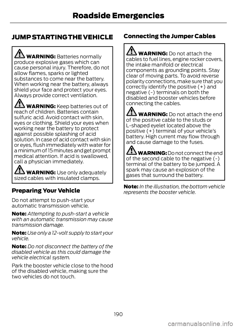
JUMP STARTING THE VEHICLE
WARNING: Batteries normally
produce explosive gases which can
cause personal injury. Therefore, do not
allow flames, sparks or lighted
substances to come near the battery.
When working near the battery, always
shield your face and protect your eyes.
Always provide correct ventilation.
WARNING: Keep batteries out of
reach of children. Batteries contain
sulfuric acid. Avoid contact with skin,
eyes or clothing. Shield your eyes when
working near the battery to protect
against possible splashing of acid
solution. In case of acid contact with skin
or eyes, flush immediately with water for
a minimum of 15 minutes and get prompt
medical attention. If acid is swallowed,
call a physician immediately.
WARNING: Use only adequately
sized cables with insulated clamps.
Preparing Your Vehicle
Do not attempt to push-start your
automatic transmission vehicle.
Note:Attempting to push-start a vehicle
with an automatic transmission may cause
transmission damage.
Note:Use only a 12-volt supply to start your
vehicle.
Note:Do not disconnect the battery of the
disabled vehicle as this could damage the
vehicle electrical system.
Park the booster vehicle close to the hood
of the disabled vehicle, making sure the
two vehicles do not touch.
Connecting the Jumper Cables
WARNING: Do not attach the
cables to fuel lines, engine rocker covers,
the intake manifold or electrical
components as grounding points. Stay
clear of moving parts. To avoid reverse
polarity connections, make sure that you
correctly identify the positive (+) and
negative (-) terminals on both the
disabled and booster vehicles before
connecting the cables.
WARNING: Do not attach the end
of the positive cable to the studs or
L-shaped eyelet located above the
positive (+) terminal of your vehicle’s
battery. High current may flow through
and cause damage to the fuses.
WARNING: Do not connect the end
of the second cable to the negative (-)
terminal of the battery to be jumped. A
spark may cause an explosion of the
gases that surround the battery.
Note:In the illustration, the bottom vehicle
represents the booster vehicle.
190
Roadside Emergencies
Page 205 of 378
Protected Component Rating Item
Blower motor control.
Upfitter - frame. 20 A 3
Starter motor. 30 A 4
Not used. — 5
Upfitter relay 4. 20 A 6
Not used. — 8
Not used. — 10
Not used. — 12
Run/start spare. 10 A 13
Adaptive cruise control. 10 A 14
Blower motor relay. 10 A 15
Air dryer. 20 A 16
Powertrain control module
- ignition status run power. 10 A 17
Glow plug control module -
ignition status run power
(diesel).
Anti-lock brake system run/
start. 10 A 18
Transmission control
module. 10 A 19
Ignition status run power
(diesel).
Windshield wiper motor. 30 A 20
Not used. — 21
Not used. — 22
Alternator 2 (dual alternator
only). 10 A 23
Body control module run
power 2 bus. 40 A 24
201
Fuses
Page 208 of 378
Protected Component Rating Item
Driver seat compressor. 20 A 63
Passenger seat compressor. 20 A 64
Upfitter - run activate feed. 10 A 65
Four pack solenoid differen-
tial lock. 10 A 66
Hydromax relay power. 10 A 67
Not used. — 69
Inverter. 40 A 70
Anti-lock brake system
valves. 30 A 71
Brake on-off switch
(hydraulic brakes). 10 A 72
Stoplamp air pressure
switch 1 and 2 (air brakes).
Not used. — 73
Heated mirror. 15 A 74
Not used. — 75
Body control module battery
feed. 60 A 76
Body control module
voltage quality monitor
power feed. 30 A 77
Transmission module
(diesel). 10 A 78
Hydromax pump monitor. 5 A 79
Trailer tow backup signal. 10 A 80
Not used. — 81
Upfitter switch (factory
location for ignition power). 5 A 82
Upfitter switch (optional
location for power at all
times). 5 A 83
204
Fuses
Page 216 of 378

Engine starting (with parking brake applied)
Check the gauge (diesel engine) or indicator light (gasoline
engine) to verify the alternator is charging. Voltmeter
Inspect for excessive free play in the steering linkages. The
steering wheel should have less than 2 in (5 cm) of free play
at its rim. Steering linkage free play
Verify the parking brake holds the vehicle by gently trying to
pull forward with the parking brake applied. Parking brake
Verify operation using the following procedure. Chock the
wheels, if necessary. Push in the parking brake and, on
tractors, push in the tractor parking brake knob: Air brakes
1. Verify the air compressor or governor cutout pressure is
approximately 120 psi (827 kPa).
2. Turn off the engine, and then turn the key back to the on
position (without starting the engine).
3. Without the brake pedal applied, note the air pressure drop
for one minute. It should be less than 2 psi (14 kPa) for single
vehicles and 3 psi (21 kPa) for combination vehicles.
4. Press and hold the brake pedal with 90 psi (621 kPa) or
more. Make sure there is no more than a 3 psi (21 kPa) per
minute leak for single vehicles and a 4 psi (28 kPa) minute
leak for combination vehicles.
5. Pump the brake pedal to deplete the system of air pressure.
The warning light and tone should turn on at 57 psi (393 kPa).
6. Pump the brake pedal and make sure the parking brake
and trailer parking brake knobs pop out at 20 psi (138 kPa)
or higher.
Verify that the fluid level is in the proper operating range. See
Automatic Transmission Fluid Check (page 242). Automatic transmission
fluid
Front of vehicle
Verify all exterior lights illuminate and are clean. Lights
Check headlights function on high and low beam.
Verify reflectors are clean, unbroken and of proper color (red
on rear, amber elsewhere).
212
Vehicle Inspection Guide
Page 221 of 378

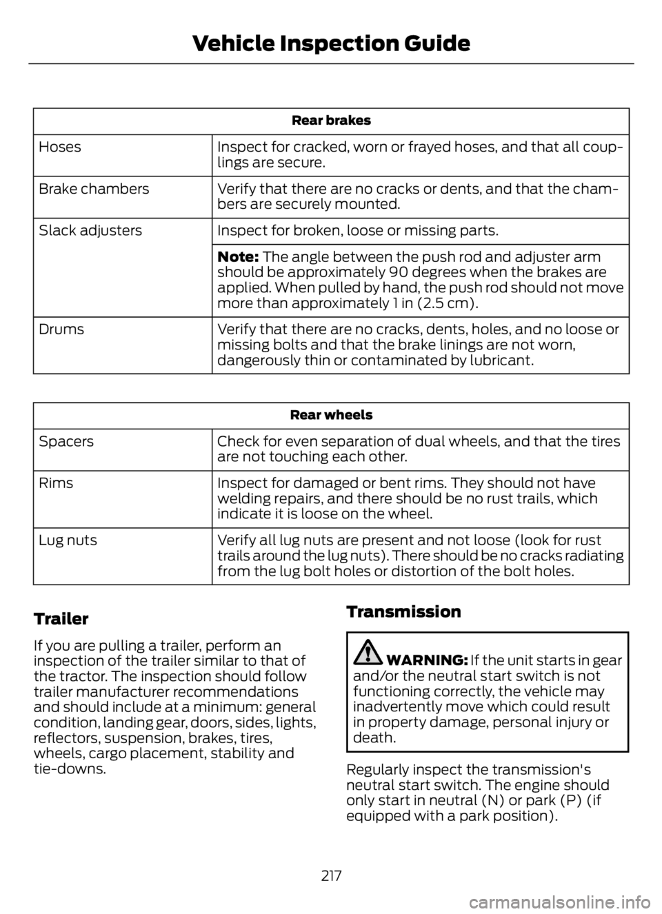
Rear brakes
Inspect for cracked, worn or frayed hoses, and that all coup-
lings are secure. Hoses
Verify that there are no cracks or dents, and that the cham-
bers are securely mounted. Brake chambers
Inspect for broken, loose or missing parts. Slack adjusters
Note: The angle between the push rod and adjuster arm
should be approximately 90 degrees when the brakes are
applied. When pulled by hand, the push rod should not move
more than approximately 1 in (2.5 cm).
Verify that there are no cracks, dents, holes, and no loose or
missing bolts and that the brake linings are not worn,
dangerously thin or contaminated by lubricant. Drums
Rear wheels
Check for even separation of dual wheels, and that the tires
are not touching each other. Spacers
Inspect for damaged or bent rims. They should not have
welding repairs, and there should be no rust trails, which
indicate it is loose on the wheel. Rims
Verify all lug nuts are present and not loose (look for rust
trails around the lug nuts). There should be no cracks radiating
from the lug bolt holes or distortion of the bolt holes. Lug nuts
Trailer
If you are pulling a trailer, perform an
inspection of the trailer similar to that of
the tractor. The inspection should follow
trailer manufacturer recommendations
and should include at a minimum: general
condition, landing gear, doors, sides, lights,
reflectors, suspension, brakes, tires,
wheels, cargo placement, stability and
tie-downs.
Transmission
WARNING: If the unit starts in gear
and/or the neutral start switch is not
functioning correctly, the vehicle may
inadvertently move which could result
in property damage, personal injury or
death.
Regularly inspect the transmission's
neutral start switch. The engine should
only start in neutral (N) or park (P) (if
equipped with a park position).
217
Vehicle Inspection Guide
Page 222 of 378
Inspect the transmission fluid level and
shift linkage for proper operation.
218
Vehicle Inspection Guide
Page 226 of 378
UNDER HOOD OVERVIEW - 6.7L DIESEL
E313700E313700
Engine compartment fuse box. See Fuses (page 200). A
Windshield washer fluid reservoir. See Washer Fluid Check (page 249). B
Automatic transmission fluid dipstick. See Automatic Transmission Fluid
Check (page 242). C
Secondary Cooling System Reservoir. See Engine Coolant Check (page 233). D
Engine coolant reservoir. See Engine Coolant Check (page 233). E
Secondary fuel filter. See Draining the Fuel Filter Water Trap (page 232). F
Engine oil separator. See Changing the Engine Oil and Oil Filter (page 226). G
Engine oil filler cap. See Engine Oil Check (page 224). H
Brake fluid reservoir. See Brake Fluid Check (page 244). I
Power steering fluid reservoir. See Power Steering Fluid Check (page 245). J
Air brake compressor. See Brake System Inspection (page 255). K
Engine oil dipstick. See Engine Oil Dipstick (page 224). L
Air cleaner assembly. See Changing the Engine Oil and Oil Filter (page 226). M
222
Maintenance