2023 FORD F650/750 transmission
[x] Cancel search: transmissionPage 227 of 378

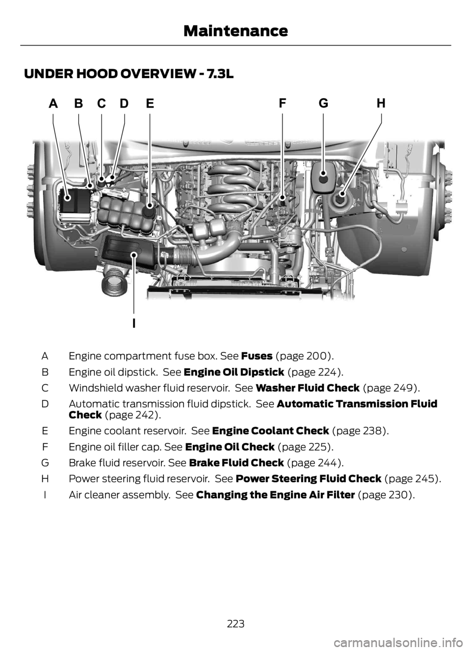
UNDER HOOD OVERVIEW - 7.3L
E330964E330964
Engine compartment fuse box. See Fuses (page 200). A
Engine oil dipstick. See Engine Oil Dipstick (page 224). B
Windshield washer fluid reservoir. See Washer Fluid Check (page 249). C
Automatic transmission fluid dipstick. See Automatic Transmission Fluid
Check (page 242). D
Engine coolant reservoir. See Engine Coolant Check (page 238). E
Engine oil filler cap. See Engine Oil Check (page 225). F
Brake fluid reservoir. See Brake Fluid Check (page 244). G
Power steering fluid reservoir. See Power Steering Fluid Check (page 245). H
Air cleaner assembly. See Changing the Engine Air Filter (page 230). I
223
Maintenance
Page 228 of 378

ENGINE OIL DIPSTICK - 6.7L
DIESEL
E249448
Minimum. A
Nominal. B
Maximum. C
ENGINE OIL DIPSTICK - 7.3L
E250320E250320
Minimum. A
Nominal. B
Maximum. C
ENGINE OIL CHECK - 6.7L
DIESEL
To check the engine oil level consistently
and accurately, do the following:1. Make sure the parking brake is on. Make
sure the transmission is in park (P) or
neutral (N).
2. Run engine until it reaches normal
operating temperature.
3. Make sure that your vehicle is on level
ground.
4. Switch the engine off and wait 15
minutes for the oil to drain into the oil
pan. Checking the engine oil level too
soon after you switch the engine off
may result in an inaccurate reading.
5. Open the hood. See Opening and
Closing the Hood (page 220).
6. Remove the dipstick and wipe it with
a clean, lint-free cloth. See Under
Hood Overview (page 222).
7. Replace the dipstick and remove it
again to check the oil level. See
Engine Oil Dipstick (page 224).
8. Make sure that the oil level is between
the maximum and minimum marks. If
the oil level is at the minimum mark,
add oil immediately. See Engine Oil
Capacity and Specification (page
292).
9. If the oil level is correct, replace the
dipstick and make sure it is fully seated.
Note:Do not remove the dipstick when the
engine is running.
Note: If the oil level is between the
maximum and minimum marks, the oil level
is acceptable. Do not add oil.
Note:The oil consumption of new engines
reaches its normal level after approximately
3,000 mi (5,000 km).
Adding Engine Oil
WARNING: Do not remove the filler
cap when the engine is running.
224
Maintenance
Page 236 of 378

E317619E317619
10. Reconnect the mass air flow sensor
electrical connector to the outlet
tube. Make sure the locking tab on
the connector is in the locked
position.
DRAINING THE FUEL FILTER
WATER TRAP - 6.7L DIESEL
Your vehicle is equipped with a diesel fuel
conditioner module located on the
frame-rail under the driver-side floorboard
near the transmission.
You should drain water from the
module assembly whenever the
warning light comes on and the
message center directs you to drain the
water separator. This will occur when
approximately 8.45 fl oz (250 ml) of water
accumulates in the module. If you allow
the water level to exceed this level, the
water may pass through to the engine and
may cause fuel injection equipment
damage.
Draining the Diesel Fuel
Conditioner Module (DFCM)
WARNING: Do not drain the
water-in-fuel separator while the engine
is running. Failure to follow this warning
may result in fire, serious injury, death or
property damage.
Note:If you drain the diesel fuel conditioner
module while the system is running air will
enter into the fuel system. The engine will
not operate properly if air enters the system.
Note:With fuel tank levels above 3⁄4 tank
it may be necessary to loosen the bowl three
turns before opening the drain. This will
actuate an anti-siphon valve at the fuel and
water separator inlet and prevent the fuel
from siphoning out of the tank.
Note:A loose drain valve can allow air to
enter the fuel system and cause drivetrain
issues. The engine will not operate properly.
Be sure that you fully tighten the drain valve.
1. Stop your vehicle and shut off the
engine.
2. Locate the diesel fuel conditioner
module and place an appropriate
container under the drain port.
E163360
232
Maintenance
Page 246 of 378

4. Check the coolant level. If the coolant
level is at or below the minimum mark,
add prediluted coolant immediately.
5. When the engine temperature cools,
you can re-start the engine. Have your
vehicle checked as soon as possible to
minimize engine damage.
Note: Driving your vehicle without repair
increases the chance of engine damage.
Engine Coolant Temperature
Management (If Equipped)
WARNING: To reduce the risk of
crash and injury, be prepared that the
vehicle speed may reduce and the
vehicle may not be able to accelerate
with full power until the coolant
temperature reduces.
If you tow a trailer with your vehicle, the
engine may temporarily reach a higher
temperature during severe operating
conditions, for example ascending a long
or steep grade in high ambient
temperatures.
At this time, you may notice the coolant
temperature gauge moves toward the red
zone and a message may appear in the
information display.
You may notice a reduction in vehicle
speed caused by reduced engine power in
order to manage the engine coolant
temperature. Your vehicle may enter this
mode if certain high-temperature and
high-load conditions take place. The
amount of speed reduction depends on
vehicle loading, grade and ambient
temperature. If this occurs, there is no
need to pull off the road. You can continue
to drive your vehicle.The air conditioning may turn on and off
during severe operating conditions to
protect the engine from overheating. When
the coolant temperature decreases to the
normal operating temperature, the air
conditioning turns on.
If the coolant temperature gauge moves
fully into the red zone, or if the coolant
temperature warning or service engine
soon messages appear in your information
display, do the following:
1. Pull off the road as soon as safely
possible and shift the transmission into
park (P).
2. Leave the engine running until the
coolant temperature gauge needle
returns to the normal position. After
several minutes, if the temperature
does not drop, follow the remaining
steps.
3. Switch the engine off and wait for it to
cool. Check the coolant level.
4. If the coolant level is at or below the
minimum mark, add prediluted coolant
immediately.
5. If the coolant level is normal, restart
the engine and continue.
AUTOMATIC TRANSMISSION
FLUID CHECK
The transmission does not consume fluid.
However, check the fluid level if the
transmission is not working properly, for
example if the transmission slips, shifts
slowly or if there are signs of fluid loss.
Replace the transmission fluid and filter
on your vehicle at the specified service
interval. See Scheduled Maintenance
(page 319).
Automatic transmission fluid expands
when warmed. To check the fluid level
consistently and accurately, do the
following:
242
Maintenance
Page 247 of 378

1. Drive the vehicle until it reaches normal
operating temperature. This may take
up to 20 mi (30 km). Make sure that
the transmission fluid temperature
gauge on the instrument cluster is
within normal operating temperature
196–215°F (91–102°C) before
checking.
2. Make sure that your vehicle is on level
ground.
3. With the engine running, parking brake
engaged and your foot on the brake
pedal, move the gearshift lever through
all of the gear ranges. Allow sufficient
time for each gear to engage.
4. Make sure the parking brake is on. Make
sure the transmission is in park (P) or
neutral (N) and leave the engine
running.
5. Open the hood. See Opening and
Closing the Hood (page 220).
6. Remove the dipstick and wipe it with
a clean, lint-free cloth. See Under
Hood Overview (page 222).
7. Replace the dipstick and remove it
again to check the fluid level.
8. If the fluid level is correct, replace the
dipstick and make sure it is fully seated.
Note:If the fluid level is between the
maximum and minimum marks, the fluid
level is acceptable. Do not add fluid.Transmission Fluid Level
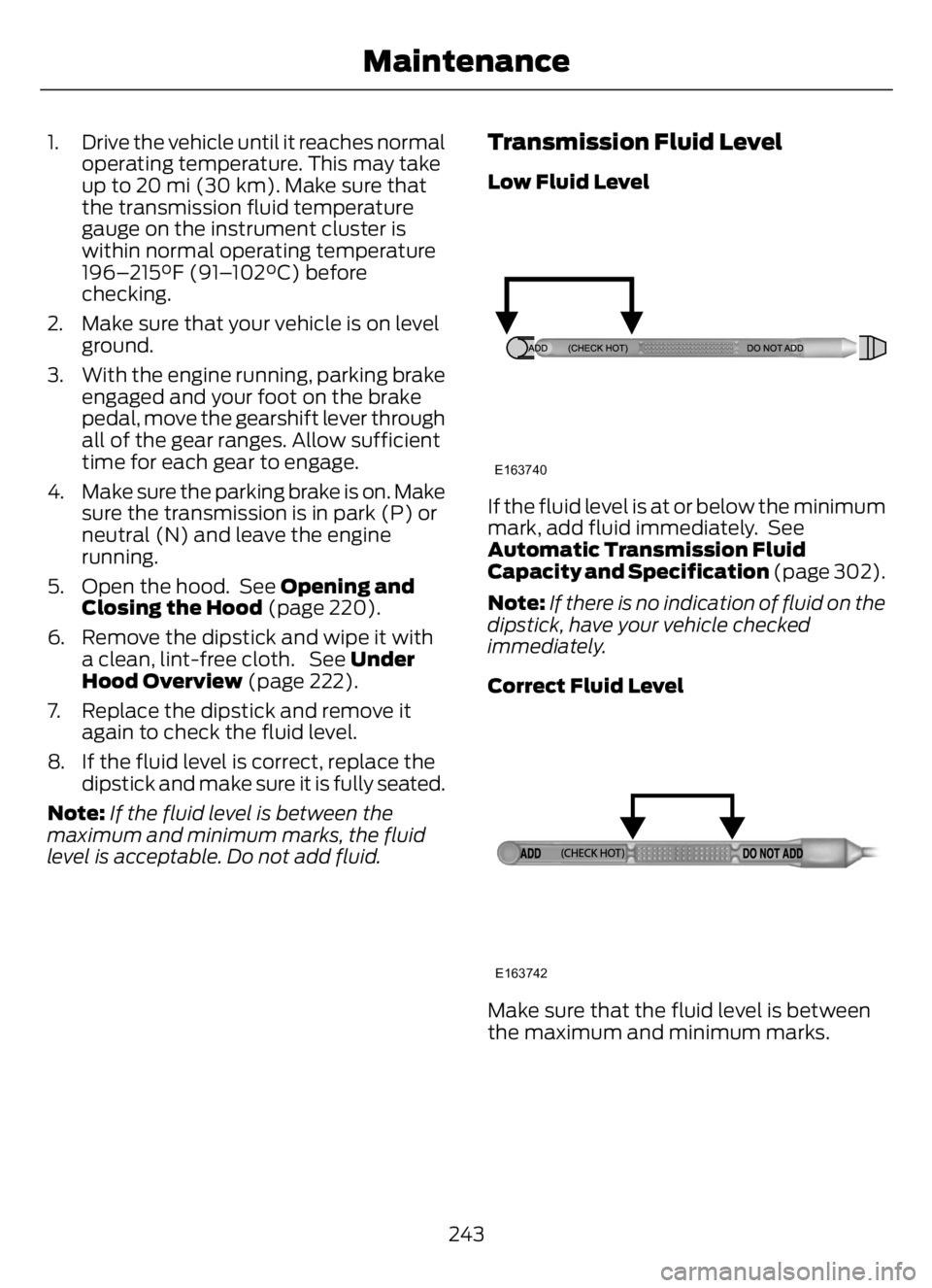
Low Fluid Level
E163740
If the fluid level is at or below the minimum
mark, add fluid immediately. See
Automatic Transmission Fluid
Capacity and Specification (page 302).
Note:If there is no indication of fluid on the
dipstick, have your vehicle checked
immediately.
Correct Fluid Level
E163742
Make sure that the fluid level is between
the maximum and minimum marks.
243
Maintenance
Page 248 of 378

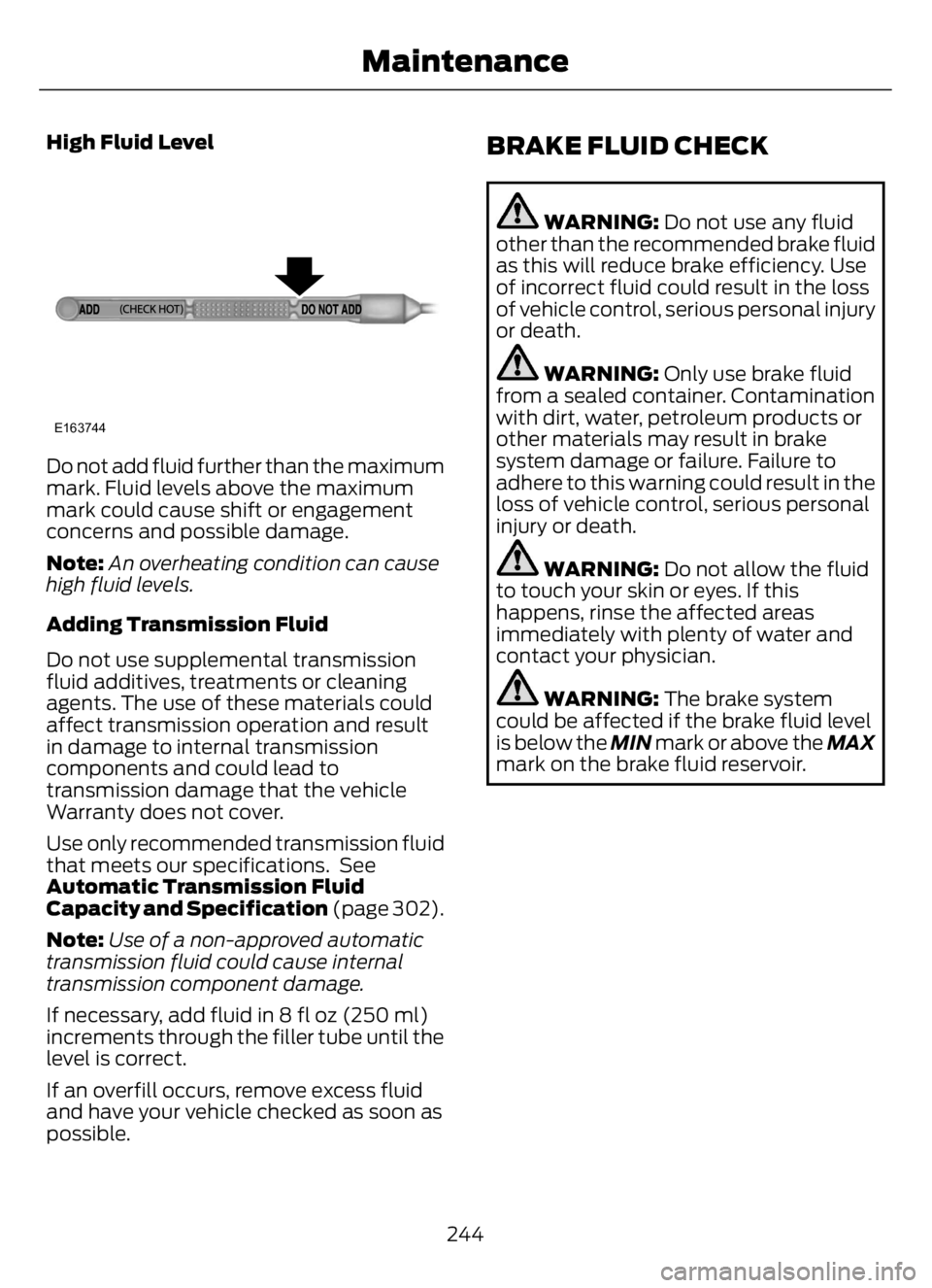
High Fluid Level
E163744
Do not add fluid further than the maximum
mark. Fluid levels above the maximum
mark could cause shift or engagement
concerns and possible damage.
Note:An overheating condition can cause
high fluid levels.
Adding Transmission Fluid
Do not use supplemental transmission
fluid additives, treatments or cleaning
agents. The use of these materials could
affect transmission operation and result
in damage to internal transmission
components and could lead to
transmission damage that the vehicle
Warranty does not cover.
Use only recommended transmission fluid
that meets our specifications. See
Automatic Transmission Fluid
Capacity and Specification (page 302).
Note:Use of a non-approved automatic
transmission fluid could cause internal
transmission component damage.
If necessary, add fluid in 8 fl oz (250 ml)
increments through the filler tube until the
level is correct.
If an overfill occurs, remove excess fluid
and have your vehicle checked as soon as
possible.
BRAKE FLUID CHECK
WARNING: Do not use any fluid
other than the recommended brake fluid
as this will reduce brake efficiency. Use
of incorrect fluid could result in the loss
of vehicle control, serious personal injury
or death.
WARNING: Only use brake fluid
from a sealed container. Contamination
with dirt, water, petroleum products or
other materials may result in brake
system damage or failure. Failure to
adhere to this warning could result in the
loss of vehicle control, serious personal
injury or death.
WARNING: Do not allow the fluid
to touch your skin or eyes. If this
happens, rinse the affected areas
immediately with plenty of water and
contact your physician.
WARNING: The brake system
could be affected if the brake fluid level
is below the MIN mark or above the MAX
mark on the brake fluid reservoir.
244
Maintenance
Page 258 of 378

2. Reconnect the fuel lines.
3. Switch the ignition on for 30 seconds
and then switch the ignition off.
Repeat this operation six times in a row
to purge any trapped air from the fuel
system.
ELECTRICAL SYSTEM
INSPECTION
Periodically inspect electrical connectors
on the outside of the cab and on the engine
and frame for corrosion and tightness.
Exposed terminals, such as the fuel sender,
cranking motor, alternator and
feed-through studs, should be cleaned and
re-coated with a lubricant sealing grease
such as Motorcraft Silicone Brake Caliper
Grease and Dielectric Compound XG-3, or
equivalent. This should include the ground
cable connector for batteries, engine and
cab as well as the jump-starting stud.
Accessory Feed Connections
Vehicle electrical systems are complex and
often include powertrain components,
such as engine and transmission controls,
instrument panels and ABS. While most
systems operate on battery voltage (12
volts), some systems can be as high as 90
volts or as low as five volts. See the
Electrical Circuit Diagram Manuals,
available from your vehicle’s manufacturer,
to make sure that any extra body lights and
accessory connections to circuits are both
appropriate and not overloaded. Do not
make modifications to any vehicle control
system without first contacting an
authorized dealer.
AIR INDUCTION SYSTEM
INSPECTION
WARNING: When performing
maintenance to any turbocharged engine
with engine air inlet piping disconnected,
keep loose clothing, jewelry and long hair
away from the engine air inlet piping. A
turbocharger compressor air inlet
protective shield should be installed over
the turbocharger air inlet to reduce the
risk of personal injury or death.
Perform a complete inspection of the air
induction system annually.
In areas where road salt is used,
disassemble the joints of each aluminum
component and inspect for salt build-up
and presence of chlorine that can cause
aluminum particles to flake off and enter
the engine combustion chambers. If
evidence of corrosion is found (usually at
the pipe connections), use a wire brush to
clean the inside of the pipes and inside the
rubber hoses.
If pitting is evident at the joint ends of the
intake pipes, use Motorcraft Silicone
Gasket and Sealant TA-30 to seal the
joints. Make sure no excess material, which
can pull into the engine, is on the inside of
the pipes. If the service condition of the
pipes, hoses or clamps is questionable,
replace the defective part(s).
Make sure to clean all dust and debris out
of the pipes and couplings with a clean,
damp rag before reassembly.
Chassis-mounted Charge Air
Cooler
Visually inspect the core assembly for
debris and clogging of external fins with
the engine off.
254
Maintenance
Page 263 of 378

Follow the tire manufacturer's
recommended cold inflation pressure for
the tire size, load range (ply rating) and
steer axle loading typical for their operation
(each steer axle tire equals ½ steer axle
loading).
Special applications may warrant a setting
based on experience with the type of tire
operating loads and conditions. Radial tires
are more sensitive to toe-in setting than
bias ply tires. Fine tuning school bus
alignment to line-haul truck standards
does not drastically improve tire tread life.
STEERING SYSTEM
INSPECTION
WARNING: Failure to maintain the
steering system in proper condition can
cause reduced steering ability resulting
in property damage, personal injury or
death.
Note:Have any steering problems
immediately corrected by a qualified service
technician.
Ask your service technician to examine the
steering mechanism. Only minor
adjustments may be necessary.
Regular inspections should include:
• Checking the tie rod, drag link end
clamp bolts and ball joints for proper
tightness.
• Checking for installation and spread of
cotter pins and tightness of nuts at
both ends of the tie rod and drag link.
• Checking that the pitman arm (steering
arm at steering gear) mounting is tight
and locked. Check system for leaks or
hose chafing. Repair immediately, if
necessary.• Maintaining proper steering gear and
power steering pump lubricant levels.
• Checking steering column joint bolts
and steering linkage, particularly for
body-to-chassis clearance.
Steering Column Joint Bolts
As a good maintenance practice, check
steering column joint bolt tightness every
60,000 mi (96,000 km) or annually,
whichever occurs first. Do not overtighten
the bolts.
Hydraulic System
Whenever draining and refilling the power
steering's hydraulic system for any reason,
bleed air from the system before returning
the vehicle to service. Failure to bleed the
hydraulic system properly can result in
degradation of power system performance.
Consult an authorized dealer who is aware
of the proper procedures for filling and
bleeding the system.
SUSPENSION SYSTEM
INSPECTION
Note:Do not adjust air suspension height
to any setting other than the specified
setting. Altering the height setting changes
the driveline angle and may result in
unwarrantable component damage, such
as transmission component damage.
Verify drive axle air suspension height and
height control valve performance at engine
oil change intervals.
Periodically check:
• Condition of spring leaves for evidence
of fatigue, bending or breakage.
• Condition of suspension mounting
brackets and bushings.
• Torque rod mounting fasteners for
tightness.
259
Maintenance