2023 FORD F650/750 tires
[x] Cancel search: tiresPage 9 of 378

Repairing Minor Paint Damage .............266
Cleaning the Wheels .................................266
Vehicle Storage ............................................267
Wheels and Tires
Tire Care .........................................................269
Using Snow Chains ....................................284
Changing a Road Wheel ..........................284
Technical Specifications .........................286
Capacities and Specifications
Engine Specifications - 6.7L Diesel ......288
Engine Specifications - 7.3L ...................289
Motorcraft Parts - 6.7L Diesel ................290
Motorcraft Parts - 7.3L ...............................291
Bulb Specification Chart ..........................292
Engine Oil Capacity and Specification -
6.7L Diesel .................................................292
Engine Oil Capacity and Specification -
7.3L ...............................................................295
Cooling System Capacity and
Specification - 6.7L Diesel ...................297
Cooling System Capacity and
Specification - 7.3L ................................298
Fuel Tank Capacity - Diesel ....................298
Fuel Tank Capacity - Gasoline ..............299
Air Conditioning System Capacity and
Specification - 6.7L Diesel ..................300
Air Conditioning System Capacity and
Specification - 7.3L .................................301
Washer Fluid Specification ......................301
Diesel Exhaust Fluid Capacity and
Specification ............................................302
Automatic Transmission Fluid Capacity
and Specification ...................................302
Brake Fluid Specification .........................303
Rear Axle Fluid Capacity and
Specification - Diesel ...........................304
Rear Axle Fluid Capacity and
Specification - Gasoline ......................305Hydraulic Power Steering Fluid Capacity
and Specification ...................................306
Vehicle Identification
Vehicle Identification Number ...............307
Connected Vehicle
Connected Vehicle Requirements .......308
Connected Vehicle Limitations .............308
Connecting the Vehicle to a Mobile
Network - Vehicles With: Modem .....308
Connected Vehicle – Troubleshooting
.......................................................................3 0 8
Audio System
General Information ..................................309
Audio Unit .....................................................309
Connecting a Bluetooth® Device ..........312
Streaming Bluetooth Audio .....................312
Playing Media From a USB Device ........312
Audio Input Jack ...........................................313
USB Port .........................................................314
Using Voice Recognition ...........................314
Accessories
Auxiliary Switches .......................................315
Ford Protect
Ford Protect ...................................................317
Scheduled Maintenance
General Maintenance Information .......319
Normal Scheduled Maintenance ..........323
Special Operating Conditions Scheduled
Maintenance ............................................329
Customer Information
Rollover Warning ........................................338
Radio Frequency Certification Labels
........................................................................338
5
Table of Contents
Page 61 of 378

Note:Using much larger tires or equipping
vehicle accessories such as snowplows can
modify your vehicle's ride height and
degrade automatic high beam control
performance.
A camera sensor, centrally mounted
behind the windshield of your vehicle,
continuously monitors conditions to turn
the high beams on and off.
Once the system is active, the high beams
turn on if:
• The ambient light level is low enough.
• There is no traffic in front of your
vehicle.
• The vehicle speed is greater than
approximately 32 mph (51 km/h).
The system turns the high beams off if:
• The ambient light level is high enough
that high beams are not required.
• The system detects an approaching
vehicle's headlamps or tail lamps.
• The vehicle speed falls below
approximately 27 mph (44 km/h).
• The system detects severe rain, snow
or fog.
• The camera is blocked.
Switching the System On and Off
Switch the system on using the information
display. See Information Displays (page
70).
E142451
Switch the lighting control to the
autolamps position. See Autolamps
(page 55).
Overriding the System
Push the lever away from you to switch
between high beam and low beam.
Automatic High Beam Indicator
The indicator illuminates to
confirm when the system is
ready to assist.
DIRECTION INDICATORS
3E3131431
Push the lever up or down to use
the direction indicators.
Note:Tap the lever up or down to make the
direction indicators flash three times.
INTERIOR LAMPS
The lamps turn on under the following
conditions:
• You open any door.
• You press a remote control button.
57
Lighting
Page 137 of 378

Note:Do not rock your vehicle for more
than a minute or damage to the
transmission and tires could occur, or the
engine could overheat.
If your vehicle is stuck in mud or snow, you
could rock it out by shifting between
forward and reverse gears, stopping
between shifts in a steady pattern. Press
lightly on the accelerator in each gear.
POWER TAKE-OFF (IF EQUIPPED)
Auxiliary equipment called power take-off,
or PTO, is often added to the engine or
transmission to operate utility equipment.
Examples include a wheel-lift for tow
trucks, cranes, tools for construction or tire
service and pumping fluids. PTO
applications draw auxiliary horsepower
from the powertrain, often while the
vehicle is stationary or mobile. In the
stationary condition, there is limited
cooling air flow through the radiator and
around the vehicle that normally occurs
when a vehicle is moving. The aftermarket
PTO system installer, having the most
knowledge of the final application, is
responsible for determining whether
additional chassis heat protection or
powertrain cooling is required and alerting
the user to the safe and proper operation.
Your vehicle is approved for use as a
Stationary Mode, SplitShaft Mode or
Mobile Mode power source within the limits
and operating guidelines detailed in the
Ford Truck Body Builders Layout Book,
found at https://fordbbas.com/home and
through the Ford Truck Body Builders
Advisory Service. The transmission power
source modes are engine specific.
133
Transmission
Page 138 of 378

GENERAL INFORMATION
WARNING: Exceeding these ratings
by overloading can cause component
failure resulting in property damage,
personal injury or death.
Fluid Temperature
If the operating temperature exceeds
250°F (121°C), the rate of axle lubrication
oxidation increases and shortens the life
of the lubricant and seals, requiring axle
lubrication changes to become more
frequent to preserve the axle. Do not
consistently run extreme pressure (EP)
lubricants above 250°F (121°C).
Axle Conversions
WARNING: When operating a
loaded vehicle, the driver must keep all
adjustable axles on the ground at all
times, supporting their share of the
vehicle’s load. Failure to do so can
overload other axles, tires, wheels,
springs, steering components, brakes
and frames, resulting in early component
failure, loss of vehicle control, possible
property damage and personal injury.
We do not recommend, or approve,
performing axle conversions. However, we
understand that, on occasion, others install
aftermarket add-on axles on the truck
chassis that allow operator control for
weight transfer from other axles (such as
air lift axles).
2-SPEED REAR AXLE (IF EQUIPPED)
WARNING: Never shift a
two-speed axle when descending a
steep grade as this may cause loss of
vehicle control and result in personal
injury.
Note:Do not shift between ranges when
the speed control is on.
A two-speed rear axle allows the driver to
select a low range for greater pulling power
and a high range for greater road speed
and fuel economy. You can also use these
ranges to provide extra steps between
transmission shifts when driving on steep
grades or fuel economy may be factors.
Axle Shifting
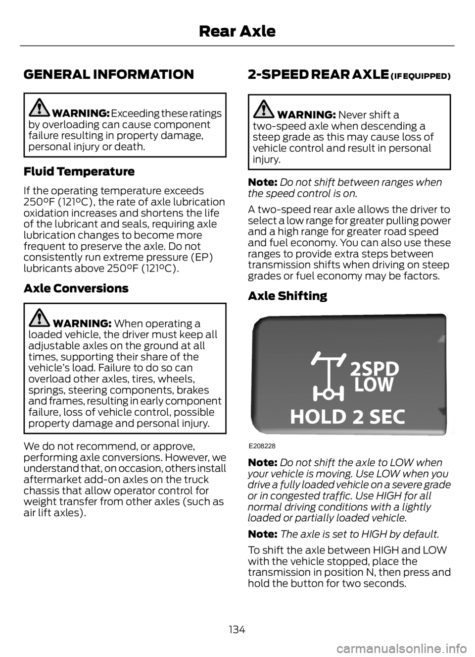
E208228
Note:Do not shift the axle to LOW when
your vehicle is moving. Use LOW when you
drive a fully loaded vehicle on a severe grade
or in congested traffic. Use HIGH for all
normal driving conditions with a lightly
loaded or partially loaded vehicle.
Note:The axle is set to HIGH by default.
To shift the axle between HIGH and LOW
with the vehicle stopped, place the
transmission in position N, then press and
hold the button for two seconds.
134
Rear Axle
Page 155 of 378

PRINCIPLE OF OPERATION -
VEHICLES WITH: HYDRAULIC
BRAKES
WARNING: Vehicle modifications
involving braking system, aftermarket
roof racks, suspension, steering system,
tire construction and wheel and tire size
may change the handling characteristics
of your vehicle and may adversely affect
the performance of the electronic
stability control system. In addition,
installing any stereo loudspeakers may
interfere with and adversely affect the
electronic stability control system. Install
any aftermarket stereo loudspeaker as
far as possible from the front center
console, the tunnel, and the front seats
in order to minimize the risk of interfering
with the electronic stability control
sensors. Reducing the effectiveness of
the electronic stability control system
could lead to an increased risk of loss of
vehicle control, vehicle rollover, personal
injury and death.
WARNING: Remember that even
advanced technology cannot defy the
laws of physics. It's always possible to
lose control of a vehicle due to
inappropriate driver input for the
conditions. Aggressive driving on any
road condition can cause you to lose
control of your vehicle increasing the risk
of personal injury or property damage.
Activation of the electronic stability
control system is an indication that at
least some of the tires have exceeded
their ability to grip the road; this could
reduce the operator's ability to control
the vehicle potentially resulting in a loss
of vehicle control, vehicle rollover,
personal injury and death. If your
electronic stability control system
activates, SLOW DOWN.
The system turns on each time you switch
the ignition on.
If a fault occurs in either the stability
control or the traction control system, the
following conditions are possible:
• The stability and traction control light
illuminate.
• The stability control and traction
control systems are not maintaining
traction of the wheels.
If a driving condition activates either the
stability control or the traction control
system, the following conditions are
possible:
• The stability and traction control light
flash.
• Your vehicle slows down.
• The system reduces engine power.
• A vibration in the brake pedal.
• The brake pedal is stiffer than usual.
• If the driving condition is severe and
your foot is not on the brake, the brake
pedal could move as the system
applies higher brake force.
The stability control system has several
features built into it to help you maintain
control of your vehicle:
Electronic Stability Control
The system assists in preventing skids or
lateral slides by applying the brakes to one
or more of the wheels individually and, if
necessary, decreases engine power.
151
Stability Control
Page 156 of 378

Traction Control
The system helps maintain traction of the
wheels by detecting and controlling wheel
spin. See Using Traction Control (page
149).
E72903
Vehicle without stability control
skidding off its intended route. A
Vehicle with stability control
maintaining control on a slippery
surface. B
PRINCIPLE OF OPERATION -
VEHICLES WITH: AIR BRAKES
WARNING: Vehicle modifications
involving braking system, aftermarket
roof racks, suspension, steering system,
tire construction and wheel and tire size
may change the handling characteristics
of your vehicle and may adversely affect
the performance of the electronic
stability control system. In addition,
installing any stereo loudspeakers may
interfere with and adversely affect the
electronic stability control system. Install
any aftermarket stereo loudspeaker as
far as possible from the front center
console, the tunnel, and the front seats
in order to minimize the risk of interfering
with the electronic stability control
sensors. Reducing the effectiveness of
the electronic stability control system
could lead to an increased risk of loss of
vehicle control, vehicle rollover, personal
injury and death.
WARNING: Remember that even
advanced technology cannot defy the
laws of physics. It's always possible to
lose control of a vehicle due to
inappropriate driver input for the
conditions. Aggressive driving on any
road condition can cause you to lose
control of your vehicle increasing the risk
of personal injury or property damage.
Activation of the electronic stability
control system is an indication that at
least some of the tires have exceeded
their ability to grip the road; this could
reduce the operator's ability to control
the vehicle potentially resulting in a loss
of vehicle control, vehicle rollover,
personal injury and death. If your
electronic stability control system
activates, SLOW DOWN.
The system automatically turns on each
time you switch the ignition on.
If a fault occurs in either the stability
control or the traction control system, you
may experience the following conditions:
• The stability and traction control light
illuminates steadily.
152
Stability Control
Page 162 of 378

The system may apply the brakes to slow
the vehicle to the new set speed. The set
speed displays continuously in the
information display when the system is
active.
Canceling the Set Speed
E265298
Press and release the button or
tap the brake pedal.
The set speed does not erase.
Resuming the Set Speed
Press and release the button.
Your vehicle speed returns to the
previously set speed and gap setting. The
set speed displays continuously in the
information display when the system is
active.
Note:Only use resume if you are aware of
the set speed and intend to return to it.
Automatic Cancellation
The system is not functional at vehicle
speeds below 12 mph (20 km/h). An
audible alarm sounds and the automatic
braking releases if the vehicle drops below
this speed.
Automatic cancellation can occur when
the tires lose traction or you apply the
parking brake.
Note:If your vehicle speed drops too low,
an audible warning sounds and a message
appears in the information display.
Automatic braking releases.
Hilly Condition and Trailer Tow
Usage
You should select a lower gear when the
system is active in situations such as
prolonged downhill driving on steep
grades, for example in mountainous areas.
The system needs additional engine
braking in these situations to reduce the
load on the vehicle’s regular brake system
to prevent it from overheating.
Note:An audible alarm sounds and the
system shuts down if it applies brakes for
an extended period of time. This allows the
brakes to cool. The system functions
normally again after the brakes cool.
Note:When towing with adaptive cruise
control, switch on Diesel engine brake.
Switching Adaptive Cruise Control
Off
E265297
Press and release the button
when the system is in standby
mode, or switch the ignition off.
Note:The set speed and gap setting is
erased when you switch the system off.
Detection Issues
WARNING: On rare occasions,
detection issues can occur due to the
road infrastructures, for example bridges,
tunnels and safety barriers. In these
cases, the system may brake late or
unexpectedly. At all times, you are
responsible for controlling your vehicle,
supervising the system and intervening,
if required.
WARNING: If the system
malfunctions, have your vehicle checked
as soon as possible.
158
Cruise Control - Vehicles With: Adaptive Cruise Control
Page 179 of 378

LOAD LIMIT
WARNING: Do not exceed
the GVWR or the GAWR
specified on the Safety
Compliance Certification Label.
WARNING: Do not use
replacement tires with lower
load carrying capacities than the
original tires because they may
lower the vehicle's GVWR and
GAWR limitations. Replacement
tires with a higher limit than the
originals do not increase the
GVWR and GAWR limitations.
WARNING: Exceeding any
vehicle weight rating limitation
could result in serious damage
to the vehicle and/or personal
injury.
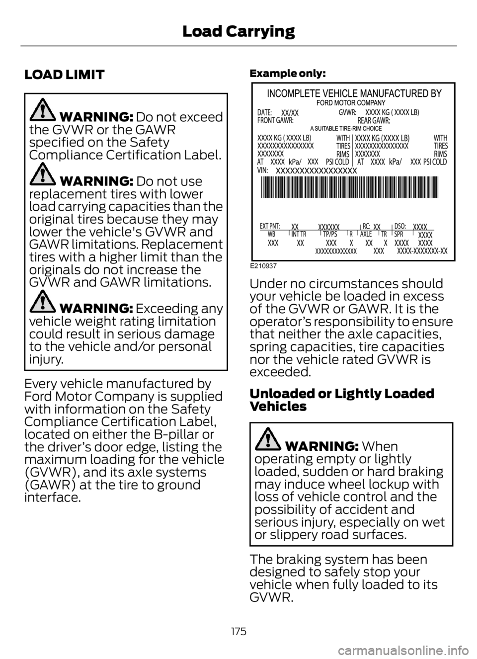
Every vehicle manufactured by
Ford Motor Company is supplied
with information on the Safety
Compliance Certification Label,
located on either the B-pillar or
the driver’s door edge, listing the
maximum loading for the vehicle
(GVWR), and its axle systems
(GAWR) at the tire to ground
interface.
Example only:
E210937
Under no circumstances should
your vehicle be loaded in excess
of the GVWR or GAWR. It is the
operator’s responsibility to ensure
that neither the axle capacities,
spring capacities, tire capacities
nor the vehicle rated GVWR is
exceeded.
Unloaded or Lightly Loaded
Vehicles
WARNING: When
operating empty or lightly
loaded, sudden or hard braking
may induce wheel lockup with
loss of vehicle control and the
possibility of accident and
serious injury, especially on wet
or slippery road surfaces.
The braking system has been
designed to safely stop your
vehicle when fully loaded to its
GVWR.
175
Load Carrying