2023 DODGE HORNET transmission oil
[x] Cancel search: transmission oilPage 8 of 288

6
SERVICING AND MAINTENANCE
SCHEDULED SERVICING ................................................ 223
Maintenance Plan ..................................................... 224
ENGINE COMPARTMENT................................................. 226 2.0L Engine .............................................................. 226Checking Oil Level ..................................................... 227
Adding Washer Fluid ................................................ 227Maintenance-Free Battery........................................ 227Pressure Washing ..................................................... 228
VEHICLE MAINTENANCE ................................................. 228 Engine Oil................................................................... 228
Engine Oil Filter ......................................................... 228
Engine Air Cleaner Filter ........................................... 229
Air Conditioner Maintenance ................................... 229
Body Lubrication ....................................................... 230Wiper Blades ............................................................ 230
Exhaust System ........................................................ 232
Cooling System.......................................................... 233
Brake System ........................................................... 236
Automatic Transmission —
If Equipped ................................................................ 236
Fuses ......................................................................... 237
Bulb Replacement ................................................... 246
TIRES ................................................................................ 246 Tire Safety Information ............................................ 246
Tires — General Information .................................... 254
Tire Types................................................................... 257
Spare Tires — If Equipped ........................................ 258Snow Traction Devices ............................................ 259
Tire Rotation Recommendations ............................ 260 DEPARTMENT OF TRANSPORTATION UNIFORM
TIRE QUALITY GRADES .................................................. 260
Treadwear ................................................................. 260Traction Grades ........................................................ 261Temperature Grades ................................................ 261
STORING THE VEHICLE ................................................... 261
BODYWORK ...................................................................... 262 Protection From Atmospheric Agents ...................... 262Body And Underbody Maintenance ......................... 262
Preserving The Bodywork ......................................... 263
INTERIORS ....................................................................... 263 Seats And Fabric Parts ............................................. 263
Plastic And Coated Parts .......................................... 264Leather Surfaces ...................................................... 264
Glass Surfaces ......................................................... 264
TECHNICAL SPECIFICATIONS
VEHICLE IDENTIFICATION NUMBER (VIN)..................... 265
BRAKE SYSTEM .............................................................. 265
WHEEL AND TIRE TORQUE SPECIFICATIONS .............. 265 Torque Specifications ............................................... 265
FUEL REQUIREMENTS ..................................................... 266 2.0L Engine ............................................................... 266Reformulated Gasoline ........................................... 266Gasoline/Oxygenate Blends ................................... 266E-85 Usage In Non-Flex Fuel Vehicles ..................... 267CNG And LP Fuel System Modifications.................. 267
Methylcyclopentadienyl Manganese
Tricarbonyl (MMT) In Gasoline ................................. 267
Materials Added To Fuel .......................................... 267Fuel System Cautions ............................................... 267 FLUID CAPACITIES ...........................................................268
ENGINE FLUIDS AND LUBRICANTS ................................269
CHASSIS FLUIDS AND LUBRICANTS ..............................269
CUSTOMER ASSISTANCE
SUGGESTIONS FOR OBTAINING SERVICE FOR
YOUR VEHICLE ................................................................. 270 Prepare For The Appointment .................................. 270
Prepare A List ............................................................ 270Be Reasonable With Requests ................................. 270
IF YOU NEED ASSISTANCE .............................................270 Roadside Assistance ................................................. 271
FCA US LLC Customer Center ................................... 272
FCA Canada Inc. Customer Care .............................. 272
Mexico ........................................................................ 272
Puerto Rico And US Virgin Islands............................ 272
Customer Assistance For The Hearing Or
Speech Impaired (TDD/TTY) ..................................... 272
Service Contract ....................................................... 272
WARRANTY INFORMATION.............................................273
MOPAR® PARTS ..............................................................273
REPORTING SAFETY DEFECTS ......................................273 In The 50 United States And Washington, D.C........ 273
In Canada................................................................... 273
PUBLICATION ORDER FORMS .......................................274
CHANGE OF OWNERSHIP OR ADDRESS.......................274
GENERAL INFORMATION................................................. 275
23_GG_OM_EN_USC_t.book Page 6
Page 11 of 288
9
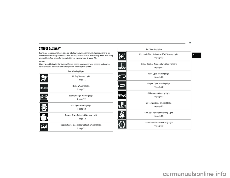
SYMBOL GLOSSARY
Some car components have colored labels with symbols indicating precautions to be
observed when using this component. It is important to follow all warnings when operating
your vehicle. See below for the definition of each symbol
Úpage 71.
NOTE:Warning and Indicator lights are different based upon equipment options and current
vehicle status. Some telltales are optional and may not appear.Red Warning Lights
Air Bag Warning Light
Úpage 71
Brake Warning Light
Úpage 71
Battery Charge Warning Light
Úpage 72
Door Open Warning Light
Úpage 72
Drowsy Driver Detected Warning Light
Úpage 72
Electric Power Steering (EPS) Fault Warning Light
Úpage 72
Electronic Throttle Control (ETC) Warning Light
Úpage 72
Engine Coolant Temperature Warning Light
Úpage 73
Hood Open Warning Light
Úpage 73
Liftgate Open Warning Light
Úpage 73
Oil Pressure Warning Light
Úpage 73
Oil Temperature Warning Light
Úpage 73
Seat Belt Reminder Warning Light
Úpage 73
Transmission Fault Warning Light
Úpage 73
Red Warning Lights
1
23_GG_OM_EN_USC_t.book Page 9
Page 70 of 288

68GETTING TO KNOW YOUR INSTRUMENT PANEL
Unstored Messages
This message type is displayed indefinitely or until the
condition that activated the message is cleared. Exam -
ples of this message type are “Turn Signal On” (if a turn
signal is left on) and “Lights On” (if driver leaves the
vehicle with the lights on).
Unstored Messages Until RUN
These messages deal primarily with the Remote Start
feature. This message type is displayed until the igni -
tion is in the RUN state. Examples of this message type
are “Remote Start Canceled - Door Ajar” and
“Press Brake Pedal and Push Button to Start.”
Five Second Unstored Messages
When the appropriate conditions occur, this type of
message takes control of the main display area for
five seconds and then returns to the previous screen.
An example of this message type is “Automatic High
Beams On.”
OIL CHANGE RESET
Use this QR code to access your digital
experience.
Your vehicle is equipped with an
engine oil change indicator system.
A message will display in the instru -
ment cluster display for five
seconds to indicate the next sched -
uled oil change interval is due. The
engine oil change indicator system is duty cycle based,
which means the engine oil change interval may fluc -
tuate, dependent upon your personal driving style.
Unless reset, this message will continue to display
each time the ignition is cycled to the ON/RUN position.
To reset the oil change indicator after performing the
scheduled maintenance, refer to the following procedure:
1. Without pressing the brake pedal, push the ENGINE START/STOP button and cycle the ignition to the
ON/RUN position (do not start the engine).
2. Fully press the accelerator pedal, slowly, three times within ten seconds.
3. Cycle the ignition to the OFF position.
NOTE:If the indicator message illuminates when you start the
vehicle, the oil change indicator system did not reset. If
necessary, repeat this procedure.
OIL CHANGE INDICATOR SYSTEM
Your vehicle is equipped with an engine oil change
indicator system. The “Oil Change Due” message will
display in the instrument cluster display for five seconds
after a single chime has sounded, to indicate the next
scheduled oil change interval. The engine oil change
indicator system is duty cycle based, which means the
engine oil change interval may fluctuate, dependent upon
your personal driving style.
GEAR SHIFT INDICATOR (GSI) —
I
F EQUIPPED
The GSI system is enabled on vehicles with a manual
transmission, or when a vehicle with an automatic
transmission is in manual shift mode. The GSI provides
the driver with a visual indication when the recommended gear shift point has been reached. This indication notifies
the driver that changing gear will allow a reduction in fuel
consumption. When the up shift indicator is shown on the
instrument cluster display, the GSI is advising the driver to
engage a higher gear. When the down shift indicator is
shown on the display, the GSI is advising the driver to
engage a lower gear.
The GSI remains illuminated until the driver changes
gears, or the driving conditions return to a situation where
changing gear is not required to improve fuel
consumption.
INSTRUMENT CLUSTER DISPLAY MENU
I
TEMS
The instrument cluster display can be used to view the
main menu items for several features. Use the up and
down arrow buttons to scroll through the driver
interactive display menu options until the desired menu is
reached.
NOTE:The instrument cluster display menu items display in the
center of the instrument cluster. Menu items may vary
depending on your vehicle features.
Main Menu
Use the Thumbwheel to scroll Up and Down through the
Menu options. Press the Thumbwheel to enter and exit the
highlighted menu option.
NOTE:These Menu options may vary based on your vehicles trim
level.
23_GG_OM_EN_USC_t.book Page 68
Page 75 of 288

GETTING TO KNOW YOUR INSTRUMENT PANEL73
Engine Coolant Temperature Warning
Light
This warning light will illuminate to warn of an
overheated engine condition. If the engine
coolant temperature is too high, this light will
illuminate and a single chime will sound.
If the light turns on while driving, safely pull over and stop
the vehicle. If the Air Conditioning (A/C) system is on, turn
it off. Also, shift the transmission into NEUTRAL (N) and
idle the vehicle. If the temperature reading does not return
to normal, turn the engine off immediately and call for
service
Úpage 218.
Hood Open Warning Light
This warning light will illuminate when the
hood is left open and not fully closed.
NOTE:If the vehicle is moving, there will also be a single chime.
Liftgate Open Warning Light
This warning light will illuminate when the
liftgate is open.
NOTE:If the vehicle is moving, there will also be a single chime.
Oil Pressure Warning Light
This warning light will illuminate to indicate low
engine oil pressure. If the light turns on while
driving, stop the vehicle, shut off the engine as
soon as possible, and contact an authorized
dealer. A chime will sound when this light turns on.
Do not operate the vehicle until the cause is corrected.
This light does not indicate how much oil is in the engine.
The engine oil level must be checked under the hood.
Oil Temperature Warning Light
This warning light will illuminate to indicate the
engine oil temperature is high. If the light turns
on while driving, stop the vehicle and shut off
the engine as soon as possible. Wait for oil
temperature to return to normal levels.
Seat Belt Reminder Warning Light
This warning light indicates when the driver or
passenger seat belt is unbuckled. When the
ignition is first placed in the ON/RUN position
and if the driver’s seat belt is unbuckled, a
chime will sound and the light will turn on. When driving, if
the driver or front passenger seat belt remains unbuckled,
the Seat Belt Reminder Light will flash or remain on
continuously and a chime will sound
Úpage 168.
Transmission Fault Warning Light —
If Equipped
This light will illuminate (together with a
message in the instrument cluster display and
a buzzer) to indicate a transmission fault.
Contact an authorized dealer if the message
remains after restarting the engine.
Vehicle Security Warning Light —
If Equipped
This light will flash at a fast rate for
approximately 15 seconds when the Vehicle
Security system is arming, and then will flash
slowly until the vehicle is disarmed.
YELLOW WARNING LIGHTS
Auto Liftgate Fault Warning Light —
If Equipped
This warning light will illuminate to signal when
there is a fault detected with the Auto Liftgate.
WARNING!
A hot engine cooling system is dangerous. You or others
could be badly burned by steam or boiling coolant. It is
recommended to call an authorized dealer for service if
your vehicle overheats
Úpage 233.
CAUTION!
Driving with a hot engine cooling system could damage
your vehicle. If the temperature gauge reads “H”, pull
over and stop the vehicle. Idle the vehicle with the air
conditioner turned off until the pointer drops back into
the normal range. If the pointer remains on the “H”,
turn the engine off immediately and call an authorized
dealer for service.
3
23_GG_OM_EN_USC_t.book Page 73
Page 78 of 288

76GETTING TO KNOW YOUR INSTRUMENT PANEL
Each tire, including the spare (if provided), should be
checked monthly when cold and inflated to the inflation
pressure recommended by the vehicle manufacturer on
the vehicle placard or tire inflation pressure label. If your
vehicle has tires of a different size than the size indicated
on the vehicle placard or tire inflation pressure label, you
should determine the proper tire inflation pressure for
those tires.
As an added safety feature, your vehicle has been equipped
with a TPMS that illuminates a low tire pressure telltale
when one or more of your tires is significantly underinflated.
Accordingly, when the low tire pressure telltale illuminates,
you should stop and check your tires as soon as possible,
and inflate them to the proper pressure. Driving on a
significantly underinflated tire causes the tire to overheat
and can lead to tire failure. Underinflation also reduces fuel
efficiency and tire tread life, and may affect the vehicle’s
handling and stopping ability.
Please note that the TPMS is not a substitute for proper
tire maintenance, and it is the driver’s responsibility to
maintain correct tire pressure, even if underinflation has
not reached the level to trigger illumination of the TPMS
low tire pressure telltale. Your vehicle has also been equipped with a TPMS
malfunction indicator to indicate when the system is not
operating properly. The TPMS malfunction indicator is
combined with the low tire pressure telltale. When the
system detects a malfunction, the telltale will flash for
approximately one minute and then remain continuously
illuminated. This sequence will continue upon subsequent
vehicle start-ups as long as the malfunction exists. When
the malfunction indicator is illuminated, the system may
not be able to detect or signal low tire pressure as
intended. TPMS malfunctions may occur for a variety of
reasons, including the installation of replacement or
alternate tires or wheels on the vehicle that prevent the
TPMS from functioning properly. Always check the TPMS
malfunction telltale after replacing one or more tires or
wheels on your vehicle to ensure that the replacement or
alternate tires and wheels allow the TPMS to continue to
function properly.
Towing Hook Breakdown Warning Light —
If Equipped
This light illuminates when there is a failure
with the tow hook. Contact an authorized
dealer for service.
Traffic Sign Recognition (TSR) Fault
Warning Light
This light will illuminate to indicate a TSR fault.
Contact an authorized dealer if the light
remains on after restarting the engine.
Transmission Temperature Warning Light
This warning light will illuminate to warn of a
high transmission fluid temperature. This may
occur with strenuous usage such as trailer
towing. If this light turns on, stop the vehicle
and run the engine at idle or slightly faster, with the
transmission in PARK or NEUTRAL, until the light turns off.
Once the light turns off, you may continue to drive
normally.
CAUTION!
Do not continue driving with one or more flat tires as
handling may be compromised. Stop the vehicle,
avoiding sharp braking and steering. If a tire puncture
occurs, repair immediately using the dedicated tire
repair kit and contact an authorized dealer as soon
as possible.
CAUTION!
The TPMS has been optimized for the original
equipment tires and wheels. TPMS pressures and
warning have been established for the tire size
equipped on your vehicle. Undesirable system
operation or sensor damage may result when using
replacement equipment that is not of the same size,
type, and/or style. Aftermarket wheels can cause
sensor damage. Using aftermarket tire sealants may
cause the Tire Pressure Monitoring System (TPMS)
sensor to become inoperable. After using an
aftermarket tire sealant it is recommended that you
take your vehicle to an authorized dealer to have your
sensor function checked.
WARNING!
If you continue operating the vehicle when the
Transmission Temperature Warning Light is illuminated
you could cause the fluid to boil over, come in contact
with hot engine or exhaust components and cause a
fire.
23_GG_OM_EN_USC_t.book Page 76
Page 84 of 288

82STARTING AND OPERATING
STOPPING THE ENGINE
Vehicles Equipped With Electronic Key
(Keyless Enter ’n Go™):
To shut off the engine with vehicle speed greater than
5 mph (8 km/h), you must push and hold the ignition or
push the ENGINE START/STOP button three times
consecutively within a few seconds. The engine will shut
down, and the ignition will be placed in the ON/RUN
position.
Turning off the car (placing the ignition from the ON/RUN
position to the OFF position), the power supply to the
accessories are maintained for a period of three minutes.
Opening the driver’s side door with the ignition in ON/RUN
will sound a short chime that reminds the driver to place
the ignition to OFF.
When the ignition is in the OFF position, the window
switches remain active for up to 10 minutes.
Opening a front door will cancel this function.
After severe driving, idle the engine to allow the
temperature inside the engine compartment to cool
before shutting off the engine.
ENGINE BREAK-IN RECOMMENDATIONS
A long break-in period is not required for the engine and
drivetrain (transmission and axle) in your vehicle.
Drive moderately during the first 300 miles (500 km).
After the initial 60 miles (100 km), speeds up to 50 or
55 mph (80 or 90 km/h) are desirable. While cruising, brief full-throttle acceleration within the
limits of local traffic laws contributes to a good break-in.
Wide-open throttle acceleration in low gear can be
detrimental and should be avoided.
The engine oil installed in the engine at the factory is a
high-quality energy conserving type lubricant. Oil changes
should be consistent with anticipated climate conditions
under which vehicle operations will occur. For the
recommended viscosity and quality grades
Úpage 269.
NOTE:A new engine may consume some oil during its first few
thousand miles (kilometers) of operation. This should be
considered a normal part of the break-in and not inter
-
preted as a problem.
PARK BRAKE
ELECTRIC PARK BRAKE (EPB)
Your vehicle is equipped with an EPB system that offers
simple operation, and some additional features that make
the parking brake more convenient and useful.
The parking brake is primarily intended to prevent the
vehicle from rolling while parked. Before leaving the
vehicle, make sure that the parking brake is applied.
Also, be certain to leave the transmission in PARK. You can engage the parking brake in two ways:
Manually, by applying the EPB switch.
Automatically, by enabling the Auto Park Brake feature
in the Customer Programmable Features section of the
Uconnect settings
Úpage 130.
The EPB switch is located in the center console.
Electric Park Brake Switch
To apply the parking brake manually, pull up on the switch
momentarily. You may hear a sound from the back of the
vehicle while the parking brake engages. Once the parking
brake is fully engaged, the Brake Warning Light in the
instrument cluster and an indicator on the switch will
illuminate. If your foot is on the brake pedal while you
apply the parking brake, you may notice a small amount of
brake pedal movement. The parking brake can be applied
even when the ignition switch is OFF and can only be
released when the ignition switch is in the ON/RUN
position.
CAUTION!
Never use Non-Detergent Oil or Straight Mineral Oil in
the engine or damage may result.
23_GG_OM_EN_USC_t.book Page 82
Page 155 of 288

MULTIMEDIA153
ACCES SO RY GAUG ES
Selecting “Accessory Gauges” will relay the following
information:
“Oil Temp” — engine oil temperature
“Transm. Temp” — transmission temperature
“Battery Voltage” — conventional battery state of
charge
Accessory Gauges
RADIO OPERATION AND MOBILE PHONES
Under certain conditions, the mobile phone being on in
your vehicle can cause erratic or noisy performance from
your radio. This condition may be lessened or eliminated
by repositioning the mobile phone within the vehicle.
This condition is not harmful to the radio. If your radio
performance does not satisfactorily improve from
repositioning the mobile phone, it is recommended that
the volume be turned down or off during mobile phone
operation when not using the Uconnect system.
RE G ULA TO RY AN D SAFE TY
I
N FO RM ATIO N
US/CANADA
Exposure to Radio Frequency Radiation
The radiated output power of the internal wireless radio is
far below the FCC and IC radio frequency exposure limits.
Nevertheless, the wireless radio will be used in such a
manner that the radio is 8 inches (20 cm) or further from
the human body. The internal wireless radio operates within guidelines
found in radio frequency safety standards and
recommendations, which reflect the consensus of the
scientific community.
The radio manufacturer believes the internal wireless
radio is safe for use by consumers. The level of energy
emitted is far less than the electromagnetic energy
emitted by wireless devices such as mobile phones.
However, the use of wireless radios may be restricted in
some situations or environments, such as aboard
airplanes. If you are unsure of restrictions, you are
encouraged to ask for authorization before turning on the
wireless radio
Úpage275.
5
23_GG_OM_EN_USC_t.book Page 153
Page 238 of 288

236SERVICING AND MAINTENANCE
BRAKE SYSTEM
In order to ensure brake system performance, all brake
system components should be inspected periodically.
For the proper maintenance intervals
Úpage 224.
Brake Master Cylinder
The fluid in the master cylinder should be checked when
performing under hood services or immediately if the
Brake Warning Light is illuminated.
Be sure to clean the top of the master cylinder area before
removing the cap. If necessary, add fluid to bring the fluid
level up to the requirements described on the brake fluid
reservoir. With disc brakes, fluid level can be expected to
fall as the brake pads wear. Brake fluid level should be
checked when pads are replaced. However, low fluid level
may be caused by a leak and a checkup may be needed.
Use only the manufacturer recommended brake fluid
Úpage 269.
AUTOMATIC TRANSMISSION —
I
F EQUIPPED
Special Additives
It is strongly recommended against using any special
additives in the transmission. Automatic Transmission
Fluid (ATF) is an engineered product and its performance
may be impaired by supplemental additives. Therefore, do
not add any fluid additives to the transmission. Avoid
using transmission sealers as they may adversely affect
seals.
Fluid Level Check
The fluid level is preset at the factory and does not require
adjustment under normal operating conditions. Routine
fluid level checks are not required; therefore the
transmission has no dipstick. An authorized dealer can
check your transmission fluid level using special service
tools. If you notice fluid leakage or transmission
malfunction, visit an authorized dealer immediately to
have the transmission fluid level checked. Operating the
vehicle with an improper fluid level can cause severe
transmission damage.
WARNING!
Riding the brakes can lead to brake failure and possibly
a collision. Driving with your foot resting or riding on the
brake pedal can result in abnormally high brake
temperatures, excessive lining wear, and possible brake
damage. You would not have your full braking capacity
in an emergency.
WARNING!
Use only the manufacturer recommended brake fluid Úpage 269. Using the wrong type of brake fluid can
severely damage your brake system and/or impair its
performance. The proper type of brake fluid for your
vehicle is also identified on the original factory
installed hydraulic master cylinder reservoir.
To avoid contamination from foreign matter or
moisture, use only new brake fluid or fluid that has
been in a tightly closed container. Keep the master
cylinder reservoir cap secured at all times. Brake
fluid in an open container absorbs moisture from the
air resulting in a lower boiling point. This may cause
it to boil unexpectedly during hard or prolonged
braking, resulting in sudden brake failure.
This could result in a collision.
Overfilling the brake fluid reservoir can result in
spilling brake fluid on hot engine parts, causing the
brake fluid to catch fire. Brake fluid can also damage
painted and vinyl surfaces, care should be taken to
avoid its contact with these surfaces.
Do not allow petroleum-based fluid to contaminate
the brake fluid. Brake seal components could be
damaged, causing partial or complete brake failure.
This could result in a collision.
CAUTION!
Do not use chemical flushes in your transmission as the
chemicals can damage your transmission components.
Such damage is not covered by the New Vehicle Limited
Warranty.
23_GG_OM_EN_USC_t.book Page 236