2023 DODGE HORNET ad blue
[x] Cancel search: ad bluePage 5 of 288

3
EXTERIOR LIGHTS ...............................................................40Multifunction Lever .................................................... 40
Headlight Switch ......................................................... 40
Daytime Running Lights (DRLs) —
If Equipped .................................................................. 40
High/Low Beam Switch ............................................. 40
Automatic High Beam Headlamp Control —
If Equipped ................................................................. 41
Flash-To-Pass .............................................................. 41
Automatic Headlights — If Equipped ......................... 41
Headlights On Automatically With Wipers —
If Equipped .................................................................. 41
Headlight Delay ........................................................... 41
Lights-On Reminder .................................................... 41
Cornering Lights — If Equipped .................................. 41
Turn Signals ................................................................ 42
Lane Change Assist ................................................... 42
Battery Saver Feature................................................. 42
INTERIOR LIGHTS................................................................42 Interior Courtesy Lights............................................... 42
WINDSHIELD WIPERS AND WASHERS ........................... 44 Windshield Wiper Operation....................................... 44
Rain Sensing Wipers — If Equipped .......................... 45
Rear Window Wiper/Washer ..................................... 46
CLIMATE CONTROLS ..........................................................46 Automatic Climate Control Descriptions And
Functions ..................................................................... 46
Automatic Temperature
Control (ATC) ............................................................... 49
Climate Voice Commands .......................................... 49
Operating Tips ............................................................ 49 INTERIOR STORAGE AND EQUIPMENT ............................ 50
Storage ......................................................................... 50
USB Control .................................................................. 51
Power Outlets — If Equipped ....................................... 52
Wireless Charging Pad —
If Equipped ................................................................... 53
WINDOWS .......................................................................... 55 Power Window Controls............................................... 55
Automatic Window Features ......................................55
Power Window System Initialization........................... 55
Window Lockout Switch ..............................................56
Wind Buffeting ............................................................ 56
POWER SUNROOF — IF EQUIPPED ................................. 56 Opening And Closing The Sunroof ..............................57
Opening And Closing The Power Sunshade ............... 57
Pinch Protect Feature.................................................. 57
Re-Initialization Procedure .......................................... 58
Sunroof Maintenance.................................................. 58
HOOD ................................................................................... 58 Opening The Hood .......................................................58
Closing The Hood ......................................................... 59
LIFTGATE .............................................................................. 59 Unlock/Open The Liftgate ........................................... 59
Lock/Close The Liftgate ..............................................60
Power Liftgate — If Equipped ......................................60
Adjustable Power Liftgate Height ............................... 61
Hands-Free Liftgate — If Equipped ............................ 62
Cargo Area Features.................................................... 63GETTING TO KNOW YOUR
INSTRUMENT PANEL
PREMIUM INSTRUMENT CLUSTER................................... 65 Instrument Cluster Descriptions
b
.......................... 66
INSTRUMENT CLUSTER DISPLAY ..................................... 66 Instrument Cluster Display Location And
Controls........................................................................ 66
Oil Change Reset
b
.................................................. 68
Oil Change Indicator System ...................................... 68
Gear Shift Indicator (GSI) —
If Equipped................................................................... 68
Instrument Cluster Display Menu Items ................... 68
Battery Saver On/Battery Saver Mode Message —
Electrical Load Reduction Actions — If Equipped ...... 70
WARNING LIGHTS AND MESSAGES ................................ 71 Red Warning Lights ..................................................... 71
Yellow Warning Lights ................................................. 73
Yellow Indicator Lights ................................................ 77
Green Indicator Lights................................................. 77
White Indicator Lights ................................................. 78
Blue Indicator Lights ................................................... 78
ONBOARD DIAGNOSTIC SYSTEM — OBD II .................... 78 Onboard Diagnostic System (OBD II)
Cybersecurity ............................................................... 79
EMISSIONS INSPECTION AND MAINTENANCE
PROGRAMS ......................................................................... 79
23_GG_OM_EN_USC_t.book Page 3
Page 14 of 288

12
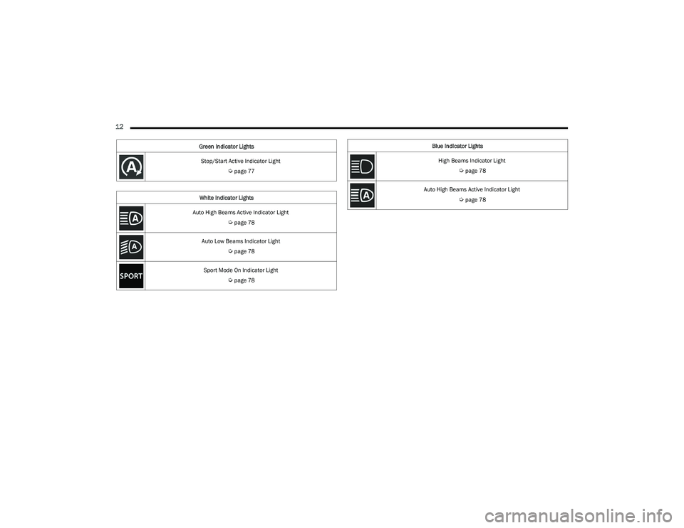
Stop/Start Active Indicator Light
Úpage 77
White Indicator Lights
Auto High Beams Active Indicator Light
Úpage 78
Auto Low Beams Indicator Light
Úpage 78
Sport Mode On Indicator Light
Úpage 78
Green Indicator Lights
Blue Indicator Lights
High Beams Indicator Light
Úpage 78
Auto High Beams Active Indicator Light
Úpage 78
23_GG_OM_EN_USC_t.book Page 12
Page 50 of 288

48GETTING TO KNOW YOUR VEHICLE
Driver And Passenger Temperature
Control Buttons
These buttons provide the driver and passenger with
independent temperature control.
SYNC Button
Press the SYNC button on the touchscreen to
toggle the Sync feature on/off. The SYNC
indicator is illuminated when SYNC is on. SYNC
is used to synchronize the passenger
temperature setting with the driver temperature setting.
Changing the passenger temperature setting while in
SYNC will automatically exit this feature.
NOTE:The SYNC button is only available on the touchscreen.
Blower Control
Blower Control is used to regulate the amount of
air forced through the Climate Control system.
There are seven blower speeds available.
Adjusting the blower will cause automatic mode
to switch to manual operation. The speeds can be selected
using either the blower control buttons on the faceplate or
the buttons on the touchscreen.
Faceplate
Press the small blower icon button to decrease the blower
speed, or press the large blower icon button to increase
the blower speed.
Touchscreen
Blower speed can also be selected by pressing a number
on the blower bar area.
Mode Control
Select Mode by pressing one of the Mode
buttons on the touchscreen, or the faceplate,
to change the airflow distribution mode. The
airflow distribution mode can be adjusted so air
comes from the instrument panel outlets, floor outlets,
defrost outlets and demist outlets.
Panel Mode
Air comes from the outlets in the instrument
panel. Each of these outlets can be individually
adjusted to direct the flow of air. The air vanes
of the center outlets and outboard outlets can
be moved up and down or side to side to regulate airflow
direction. There is a shut-off wheel located below the air
vanes to shut off or adjust the amount of airflow from
these outlets.
Bi-Level Mode
Air comes from the instrument panel outlets
and floor outlets. A slight amount of air is
directed through the defrost and side window
demister outlets.
NOTE:Bi-Level mode is designed under comfort conditions to
provide cooler air out of the panel outlets and warmer air
from the floor outlets.
Floor Mode
Air comes from the floor outlets. A slight
amount of air is directed through the defrost,
side window demister outlets, and panel
outboard outlets.
Defrost Mode
Air comes from the windshield and side
window demist outlets. When the defrost
button is selected, the blower level may
increase. Use Defrost mode with maximum
temperature settings for best windshield and side window
defrosting and defogging. When toggling the front defrost
mode button, the Climate Control system will return to the
previous setting.
Mix Mode
Air is directed through the floor, defrost, and
side window demister outlets. This setting
works best in cold or snowy conditions that
require extra heat to the windshield. This
setting is good for maintaining comfort while reducing
moisture on the windshield. A slight amount of air is also
directed through the panel outboard outlets.
Push upward on the driver’s or
passenger’s side toggle switch on the
faceplate, or press and slide the
temperature bar towards the red arrow
button on the touchscreen for warmer
temperature settings.
Push downward the driver’s or
passenger’s side toggle switch on the
faceplate, or press and slide the
temperature bar towards the blue arrow
button on the touchscreen for cooler
temperature settings.
23_GG_OM_EN_USC_t.book Page 48
Page 56 of 288

54GETTING TO KNOW YOUR VEHICLE
The wireless charging pad is equipped with an anti-slip
mat to hold your mobile phone in place, and an LED
indicator light.
Place the device inside the prepared area delimited in the
mat as shown in the image. Incorrect positioning will
prevent the phone from charging.
Correct Phone Position
LED Indicator Status:
No Light: Charging pad is idle or searching for a device.
Device may not be compatible with the Qi
® standard.
Blue Light: Device is detected and is charging.
Red Light/Flashing: Internal error, or foreign object is
detected.
Green Light: Device has completed battery charging
(if device is equipped to transmit this information). Important Notes Regarding This Vehicle’s Wireless
Charging Pad:
The presence of the NFC function active on a smart -
phone could signal malfunction anomalies.
The ignition must be in the ON/RUN position in order
for the phone to charge.
To avoid interference with the key fob search, the wire -
less charging pad will stop charging when any door is
opened.
Be sure to place the mobile device correctly (display
facing upward, and phone not covering the LED) on the
wireless charging pad.
Wireless charging is not as fast as when the phone is
connected to a wired charger.
The phone’s protective case must be removed when
placed on the wireless charging pad.
iPhone
® 12 (including iPod®) is equipped with soft -
ware to protect the device from overheating. When the
software is active, the rate of charge is slowed down to
protect the device.
Phones must always be placed on the wireless
charging pad within the outline shown on the pad so
that its charging parts connect with the charging coils
of the system. Movement of the phone during charging
may prevent or slow the rate of charge.
Having multiple applications open on the phone while
charging will reduce the charging efficiency, and may
even shut down an application that is actively running
(i.e. Apple CarPlay
®). This may also cause the phone to
overheat.
Wireless chargers may implement certain methods to
prevent the phone from overheating during charging
such as slowing down the rate of charge. In certain
instances, the device may shut down for a brief period
of time (when the device reaches a certain tempera -
ture). If this happens, it does not mean there is a fault
with the wireless charging pad. This may just be a
protective measure to prevent damage to the phone.
The use of multiple wireless functions at the same time
(wireless charging, Apple CarPlay
®, Android Auto™)
could cause the device to overheat, resulting in limita -
tion of the functions or it turning off. In this case, it is
recommended to connect the system using t
he USB port.
Do not place the key fob or any other type of metal/
magnetized object inside the mobile phone housing or
near the wireless charging pad.
CAUTION!
The key fob should not be placed on the charging pad
or within 6 inches (15 cm) of it. Doing so can cause
excessive heat buildup and damage to the fob. Placing
the fob in close proximity of the charging pad blocks the
fob from being detected by the vehicle and prevents the
vehicle from starting.
23_GG_OM_EN_USC_t.book Page 54
Page 71 of 288

GETTING TO KNOW YOUR INSTRUMENT PANEL69
SPEEDOMETER
The Speedometer menu options may consist of the
following:
Digital speed and speed unit (MPH or km/h)
Gear Shift Indicator (GSI)
Gear
Drive mode name
The speed units can be changed from MPH to km/h by
pressing the Thumbwheel.
NAVIGATION — IF EQUIPPED
Turn the Thumbwheel up or down to increase or decrease
the zoom on this screen. Press the Thumbwheel to go
back to the initial frame. The zoom level is automatically
reset to the factory settings whenever the engine is
restarted.
The following information is shown:
Direction Indicators
Distance to next change of direction (in miles or kilome -
ters, depending on instrument panel settings)
Suggested lanes
Address of the road to be followed after the change of
direction Press and hold the Thumbwheel to disable the indications
in the right-hand ring for the current navigation. If a
predicted route is selected, the route shall start without
further confirmation.
NOTE:During projection modes (Apple CarPlay® or
Android Auto™) the native map is not available.
PHONE
This menu displays the current status of a phone
connected to the vehicle via Bluetooth®. The System
supports up to two phones connected at the same time.
Information available in cluster depends on which phone
is dynamically selected by the user in each moment (i.e.
the phone in focus), to enter and select one of the phone
connected user should press Thumbwheel
If no phone is connected, the menu will not function when
the
OK button is pushed. Otherwise, if a phone is
connected, push the OK button to enter the menu.
The following items will display:
Recent calls: displays a list of the last 10 calls.
SMS reader: displays the last 10 text messages and if
they are read or unread.
Favorite numbers: displays a maximum of 10 favorite
numbers.
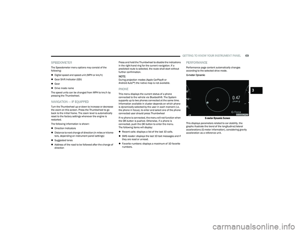
PERFORMANCE
Performance page content automatically changes
according to the selected drive mode.
G-meter Dynamic
G-meter Dynamic Screen
This displays parameters related to car stability, the
graphs illustrate the trend of the longitudinal/lateral
accelerations (G-meter information), considering gravity
acceleration as a reference unit.
3
23_GG_OM_EN_USC_t.book Page 69
Page 80 of 288

78GETTING TO KNOW YOUR INSTRUMENT PANEL
WHITE INDICATOR LIGHTS
Automatic High Beam Indicator Light —
If Equipped
This indicator appears when the automatic
high beam headlights are on Úpage 40.
Automatic Low Beam Indicator Light —
If Equipped
This indicator appears when the automatic low
beam headlights are on Úpage 40.
Sport Mode On Indicator Light
This light will turn on when Sport mode on
is active.
BLUE INDICATOR LIGHTS
High Beam Indicator Light
This indicator light will illuminate to indicate
that the high beam headlights are on. With the
low beams activated, push the multifunction
lever forward (toward the front of the vehicle) to
turn on the high beams. Pull the multifunction lever
rearward (toward the rear of the vehicle) to turn off the
high beams. If the high beams are off, pull the lever toward
you for a temporary high beam on, “flash to pass”
scenario.
Automatic High Beam Indicator Light —
If Equipped
This indicator shows that the automatic high
beam headlights are on Úpage 40.
ONBOARD DIAGNOSTIC SYSTEM — OBD II
Your vehicle is equipped with a sophisticated Onboard
Diagnostic system called OBD II. This system monitors the
performance of the emissions, engine, and automatic
transmission control systems. When these systems are
operating properly, your vehicle will provide excellent
performance and fuel economy, as well as emissions well
within current government regulations.
If any of these systems require service, the OBD II system
will turn on the Malfunction Indicator Light (MIL). It will
also store diagnostic codes and other information to
assist your service technician in making repairs. Although
your vehicle will usually be drivable and not need towing,
see an authorized dealer for service as soon as possible.
CAUTION!
Prolonged driving with the MIL on could cause further
damage to the emission control system. It could also
affect fuel economy and driveability. The vehicle
must be serviced before any emissions tests can be
performed.
If the MIL is flashing while the vehicle is running,
severe catalytic converter damage and power loss
will soon occur. Immediate service is required.
23_GG_OM_EN_USC_t.book Page 78
Page 140 of 288

138MULTIMEDIA
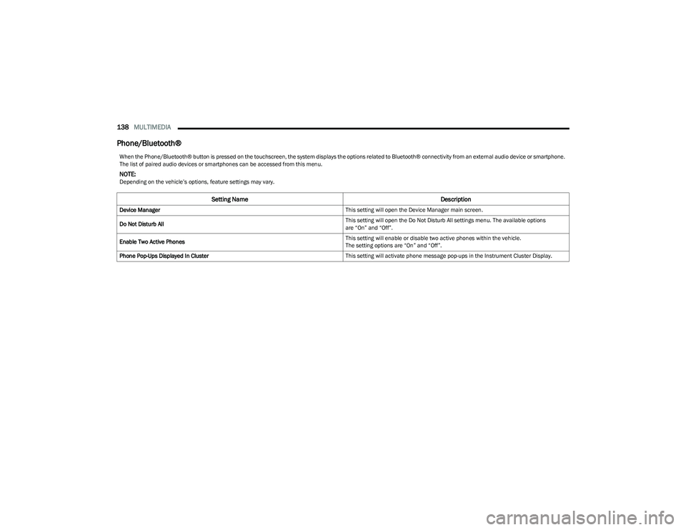
Phone/Bluetooth®
When the Phone/Bluetooth® button is pressed on the touchscreen, the system displays the options related to Bluetooth® connectivity from an external audio device or smartphone.
The list of paired audio devices or smartphones can be accessed from this menu.
NOTE:Depending on the vehicle’s options, feature settings may vary.
Setting Name Description
Device Manager This setting will open the Device Manager main screen.
Do Not Disturb All This setting will open the Do Not Disturb All settings menu. The available options
are “On” and “Off”.
Enable Two Active Phones This setting will enable or disable two active phones within the vehicle.
The setting options are “On” and “Off”.
Phone Pop-Ups Displayed In Cluster This setting will activate phone message pop-ups in the Instrument Cluster Display.
23_GG_OM_EN_USC_t.book Page 138
Page 152 of 288

150MULTIMEDIA
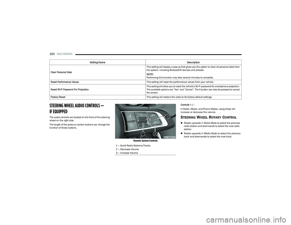
STEERING WHEEL AUDIO CONTROLS —
IF EQUIPPED
The audio controls are located on the front of the steering
wheel on the right side.
The length of the press on certain buttons can change the
function of these buttons.
Remote System Controls
Controls + / -
In Radio, Media, and Phone Modes, using these will
increase or decrease the volume.
STEERING WHEEL ROTARY CONTROL
Rotate upwards in Radio Mode to select the previous
radio station and downwards to select the next radio
station.
Rotate upwards in Media Mode to select the previous
track and downwards to select the next track.
Clear Personal Data
This setting will display a pop-up that gives you the option to clear all personal data from
the system, including Bluetooth® devices and presets.
NOTE:Performing this function may take several minutes to complete.
Reset Performance Values This setting will reset the performance values from your vehicle.
Reset Wi-Fi Password For Projection This setting will allow you to reset the vehicle’s Wi-Fi password for smartphone projection.
The available options are “Yes” and “Cancel”. The X button can also be pressed to cancel
the screen.
Factory Reset This setting will restore the radio to its factory default settings.
Setting NameDescription
1 — Scroll Radio Stations/Tracks
2 — Decrease Volume
3 — Increase Volume
23_GG_OM_EN_USC_t.book Page 150