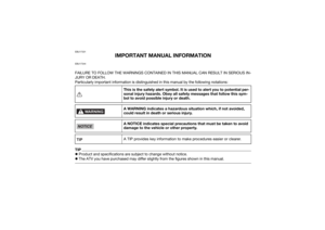
Page 25 of 126
3-7
3
UBD366E0.book Page 7 Thursday, June 10, 2021 2:39 PM
Page 26 of 126
4-1
4
EBU17681
DESCRIPTION
EBU17691Left view
EBU17701Right view
1. Fuel tank cap
2. Fuel cock
3. Air filter
4. Fuse
5. Battery
6. Rear shock absorber
7. Kickstarter lever cap
1 2 3 4,576
1. Spark arrester
2. Reflector
3. Tool kit
4. Front shock absorber
5. Spark plug
6. Engine oil filler cap
7. Transmission oil filler cap123 4
76 5
UBD366E0.book Page 1 Thursday, June 10, 2021 2:39 PM
Page 27 of 126
4-2
4
EBU17715Controls and instruments1. Rear brake lever
2. Handlebar switches
3. Parking brake lock plate
4. Starter (choke) lever
5. Main switch
6. Throttle lever
7. Front brake lever
8. Drive select lever
1
2
3
5
6
7
4
8
UBD366E0.book Page 2 Thursday, June 10, 2021 2:39 PM
Page 28 of 126
5-1
5
EBU17739
INSTRUMENT AND CONTROL FUNCTIONS
EBU33850Main switchThe positions of the main switch are as follows:
ON
All electrical systems are supplied with power, and
the engine can be started. The key cannot be re-
moved.
OFF
All electrical systems are off. The key can be re-
moved.
EBU17794Indicator lightsEBU17861Neutral indicator light “ ”
This indicator light comes on when the transmis-
sion is in the neutral position.EBU17831Reverse indicator light “ ”
This indicator light comes on when the transmis-
sion is in the reverse position.
ON
OFF
1. Reverse indicator light
Page 29 of 126
5-2
5
EBU18068Handlebar switchesEBU18081Engine stop switch “ / ”
Set this switch to “ ” before starting the engine.
The engine stop switch controls the ignition and
stops the engine when it is running. Use this
switch to stop the engine in an emergency situa-
tion. The engine will not start or run when this
switch is set to “ ”.
EBU18102Start switch “ ”
Push this switch to crank the engine with the start-
er. See the starting instructions on page 7-1 prior
to starting the engine.EBU18286Throttle leverPush the throttle lever to increase engine speed.
Spring tension returns the lever to the rest position
when released. Always check that the throttle le-
ver returns normally before starting the engine.
1. Engine stop switch “ / ”
2. Start switch “ ”
21
1. Throttle lever
1
UBD366E0.book Page 2 Thursday, June 10, 2021 2:39 PM
Page 30 of 126

5-3
5
EBU33802Speed limiterYour ATV was delivered with two speed limiter de-
vices. A vehicle speed limiter adjusting screw and
a removable engine speed limiter plate. Yamaha
recommends that all beginning riders start off with
the vehicle speed limiter adjusting screw fully
turned in and the engine speed limiter plate in-
stalled to limit the amount of speed available while
they learn.
The vehicle speed limiter keeps the throttle from
fully opening, even when the throttle lever is
pushed to the maximum. The adjusting screw may
be gradually turned out as the beginner becomes
more familiar with operating the ATV. Parents
should decide when to adjust the ATV for more
power as their youngster’s riding skills improve.
Once the ATV rider can operate with skill at the top
speed permitted by adjusting the vehicle speed
limiter alone, the engine speed limiter plate can be
removed. Since removal of this plate will result in
a significant increase in power, turn the vehicle
speed limiter adjusting screw completely back in
again and adjust it out in stages as done previous-
ly.Vehicle speed limiter
1. Loosen the locknut.
2. To increase the maximum engine power available and the maximum speed of the ATV,
turn the adjusting screw in direction (a). To
decrease the maximum engine power avail-
able and the maximum speed of the ATV, turn
the adjusting screw in direction (b). Do not
turn the adjusting screw out more than 14.5
mm (0.57 in) or the throttle cable could be
damaged. Always make sure the throttle lever
free play is adjusted to 1.5–4.0 mm (0.06–
0.16 in). (See page 9-20.) WARNING! Im-
proper adjustment of the speed limiter and
throttle could cause throttle cable damage
or improper throttle operation. You could
lose control, resulting in an accident.
[EWB00242]
UBD366E0.book Page 3 Thursday, June 10, 2021 2:39 PM
Page 31 of 126
5-4
5
3. Tighten the locknut.
Engine speed limiter plate
When the engine speed limiter plate is installed,
engine speed is limited to 4900 r/min. When this
plate is removed, top engine speed (8500 r/min) is
available.
Remove the plate as follows. 1. Remove the seat. (See page 5-13.)
2. Loosen the screws, and then remove the plate as shown. 3. Tighten the screws.
4. Install the seat.
TIPStore the engine speed limiter plate with the Own-
er’s Manual so that it is readily available whenever
you want to reduce top engine speed.
1. Locknut
2. Adjusting screw
3. No more than 14.5 mm (0.57 in)
1
3
2
(b)
(a)
1. Screw
2. Engine speed limiter plate
12
UBD366E0.book Page 4 Thursday, June 10, 2021 2:39 PM
Page 32 of 126
5-5
5
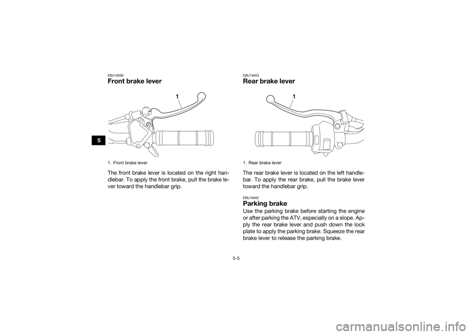
EBU18393Front brake leverThe front brake lever is located on the right han-
dlebar. To apply the front brake, pull the brake le-
ver toward the handlebar grip.
EBU18403Rear brake leverThe rear brake lever is located on the left handle-
bar. To apply the rear brake, pull the brake lever
toward the handlebar grip.EBU18462Parking brakeUse the parking brake before starting the engine
or after parking the ATV, especially on a slope. Ap-
ply the rear brake lever and push down the lock
plate to apply the parking brake. Squeeze the rear
brake lever to release the parking brake.
1. Front brake lever
1
1. Rear brake lever
1
UBD366E0.book Page 5 Thursday, June 10, 2021 2:39 PM