Page 41 of 110
The brake control system regulates hy-
draulic brake pressure for the front and
rear wheels independently when the
brakes are")
Instrument and control functions
4-20
4
EAU91461
Brake control system (BC)The brake control system regulates hy-
draulic brake pressure for the front and
rear wheels independently when the
brakes are applied and wheel lock is
detected. This system has two settings
which can be changed in the settings
MENU. (See page 4-15.)
BC1 is standard ABS, which adjusts
brake pressure based on vehicle
speed and wheel speed data. BC1 is
designed to engage and maximize
braking when the vehicle is upright.
BC2 uses additional data from the IMU
to regulate applied brake power when
cornering to suppress lateral wheel
slip.
Regarding ABS, operate the brakes as
you would conventional brakes. When
the brake control system engages, a
pulsating sensation may be felt at the
brake lever or brake pedal as the hy-
draulic unit rapidly applies and reduces
brake pressure. In this situation, con-
tinue to apply the brake lever and
brake pedal to allow the ABS to work—
do not “pump the brakes” as this will
reduce braking effectiveness.
WARNING
EWA16051
Always keep a sufficient d istance
from the vehicle ahead to match the
ri din g speed even with ABS.
The ABS performs best with
lon g b rakin g d istances.
On certain surfaces, such as
rou gh or g ravel roa ds, the b rak-
in g d istance may be lon ger with
the ABS than without.The ABS hydraulic unit is monitored by
the ABS ECU, which will revert the sys-
tem to conventional braking if a mal-
function occurs.
WARNING
EWA20891
The brake control system is not a
su bstitute for the use of proper ri d-
in g an d brakin g techniques. The
b rake control system cannot pre-
vent all loss of traction due to over-
b rakin g from excessive spee d, or
lateral wheel slip when brakin g on
slippery surfaces.
TIPThe ABS performs a self-diagnostic
test when the vehicle is started and
reaches a speed of 5 km/h (3 mi/h).
During this test, a clicking noise may
be audible from the hydraulic control
unit, and a vibration may be felt at the
brake lever or pedal, but this is normal.NOTICE
ECA20100
Be careful not to d amage the wheel
sensor or wheel sensor rotor; other-
wise, improper performance of the
ABS will result.1. Front wheel sensor rotor
2. Front wheel sensor
1 1 1
2 2
UB7NE1E0.book Page 20 Friday, September 3, 2021 11:25 AM
Page 42 of 110
Instrument and control functions
4-21
4
EAU13077
Fuel tank capTo open the fuel tank cap
Open the fuel tank cap lock cover, in-
sert the key, and then turn it 1/4 turn
clockwise. The lock will be released
and the fuel tank cap can be opened.
To close the fuel tank cap
With the key still inserted, push down
the fuel tank cap. Turn the key 1/4 turn
counterclockwise, remove it, and then
close the lock cover.
TIPThe fuel tank cap cannot be closed un-
less the key is in the lock. In addition,
the key cannot be removed if the cap is
not properly closed and locked.
WARNING
EWA11092
Make sure that the fuel tank cap is
properly close d after fillin g fuel.
Leakin g fuel is a fire hazar d.
1. Rear wheel sensor rotor
2. Rear wheel sensor
1 1 1 2 2
1. Fuel tank cap lock cover
2. UnlockK
1
2
UB7NE1E0.book Page 21 Friday, September 3, 2021 11:25 AM
Page 43 of 110

Instrument and control functions
4-22
4
EAU13222
FuelMake sure there is sufficient gasoline in
the tank.
WARNING
EWA10882
Gasoline an d gasoline vapors are
extremely flammab le. To avoid fires
an d explosions an d to re duce the
risk of injury when refueling , follow
these instructions.1. Before refueling, turn off the en- gine and be sure that no one is sit-
ting on the vehicle. Never refuel
while smoking, or while in the vi-
cinity of sparks, open flames, or
other sources of ignition such as
the pilot lights of water heaters
and clothes dryers.
2. Do not overfill the fuel tank. When refueling, be sure to insert the
pump nozzle into the fuel tank filler
hole. Stop filling when the fuel
reaches the bottom of the filler
tube. Because fuel expands when
it heats up, heat from the engine or
the sun can cause fuel to spill out
of the fuel tank. 3. Wipe up any spilled fuel immedi-
ately. NOTICE: Immediately
wipe off spille d fuel with a clean,
d ry, soft cloth, since fuel may
d eteriorate painte d surfaces or
plastic parts.
[ECA10072]
4. Be sure to securely close the fuel tank cap.
WARNING
EWA15152
Gasoline is poisonous an d can
cause injury or d eath. Handle gaso-
line with care. Never siphon gasoline
b y mouth. If you shoul d swallow
some gasoline or inhale a lot of gas-
oline vapor, or g et some gasoline in
your eyes, see your doctor imme di- ately. If g
asoline spills on your skin,
wash with soap an d water. If gaso-
line spills on your clothin g, chan ge
your clothes.
EAU86072
Your Yamaha engine was designed to
use unleaded gasoline with a research
octane number of 95 or higher. If en-
gine knocking or pinging occurs, use a
gasoline of a different brand or higher
octane rating.
1. Fuel tank filler tube
2. Maximum fuel level
1
2
Recommen ded fuel:
Unleaded gasoline (E10 acceptable)
Octane num ber (RON):
95
Fuel tank capacity: 14 L (3.7 US gal, 3.1 Imp.gal)
Fuel tank reserve:
2.8 L (0.74 US gal, 0.62 Imp.gal)
UB7NE1E0.book Page 22 Friday, September 3, 2021 11:25 AM
Page 44 of 110
.
Confirm the gasoline pump nozzle
has the sa")
Instrument and control functions
4-23
4
TIP This mark identifies the recom-
mended fuel for this vehicle as
specified by European regulation
(EN228).
Confirm the gasoline pump nozzle
has the same fuel identification
mark.Gasohol
There are two types of gasohol: gaso-
hol containing ethanol and that con-
taining methanol. Gasohol containing
ethanol can be used if the ethanol con-
tent does not exceed 10% (E10). Gas-
ohol containing methanol is not
recommended by Yamaha because it
can cause damage to the fuel system
or vehicle performance problems.
NOTICE
ECA11401
Use only unlea ded g asoline. The use
of lea ded g asoline will cause severe
d amag e to internal en gine parts,
such as the valves an d piston rin gs,
as well as to the exhaust system.
EAU86160
Fuel tank overflow hoseThe overflow hose drains excess gaso-
line and directs it safely away from the
vehicle.
Before operating the vehicle: Check the fuel tank overflow hose
connection.
Check the fuel tank overflow hose
for cracks or damage, and replace
it if necessary.
Make sure that the fuel tank over-
flow hose is not blocked, and
clean it if necessary.
Make sure that the fuel tank over-
flow hose is positioned as shown.
E5
E10
1. Fuel tank overflow hose
2. White mark
3. Clamp
111
32
22
UB7NE1E0.book Page 23 Friday, September 3, 2021 11:25 AM
Page 45 of 110
 to reduce harmful exhaust
emissions.
W")
Instrument and control functions
4-24
4
TIPSee page 7-10 for canister information.
EAU13435
Catalytic converterThe exhaust system contains catalytic
converter(s) to reduce harmful exhaust
emissions.
WARNING
EWA10863
The exhaust system is hot after op-
eration. To prevent a fire hazar d or
b urns:
Do not park the vehicle near
possi ble fire hazar ds such as
g rass or other materials that
easily burn.
Park the vehicle in a place
where pe destrians or child ren
are not likely to touch the hot
exhaust system.
Make sure that the exhaust sys-
tem has cooled down before
d oin g any maintenance work.
Do not allow the en gine to id le
more than a few minutes. Lon g
i d lin g can cause a buil d-up of
heat.
EAU57992
SeatTo remove the seat 1. Open the seat lock cover, insert the key into the seat lock, and then
turn the key counterclockwise.
2. While holding the key in that posi- tion, slide the seat backward and
then lift the rear of the seat up, and
then pull the seat off.
To install the seat 1. Insert the projections into the seat holders as shown.1. Seat lock cover
2. Seat lock
3. Unlock.
3 3
1 2 3
1
2
UB7NE1E0.book Page 24 Friday, September 3, 2021 11:25 AM
Page 46 of 110
Instrument and control functions
4-25
4
2. Push the rear of the seat down tolock it in place.
3. Remove the key.
TIPMake sure that the seat is properly se-
cured before riding.
EAU91560
Ri der footrest positionThe rider footrests can be adjusted to
one of two positions. From the factory,
the footrests are in the low position.
Have a Yamaha dealer adjust the posi-
tions of the rider footrests.
EAU46833
Han dle bar position The handlebar can be adjusted to one
of two positions to suit the rider’s pref-
erence. Have a Yamaha dealer adjust
the position of the handlebar.
1. Projection
2. Seat holder2 2 2 1
1
1. Handlebar
1
UB7NE1E0.book Page 25 Friday, September 3, 2021 11:25 AM
Page 47 of 110

Instrument and control functions
4-26
4
EAU76345
A djustin g the front fork
WARNING
EWA14671
Always a djust the sprin g preloa d on
b oth fork leg s equally, otherwise
poor han dlin g an d loss of sta bility
may result.Each front fork leg is equipped with a
spring preload adjusting bolt, the right
front fork leg is equipped with a re-
bound damping force adjusting screw
and the left front fork leg with a com-
pression damping force adjusting
screw.NOTICE
ECA10102
To avoi d d amag ing the mechanism,
d o not attempt to turn b eyond the
maximum or minimum settin gs.Sprin g preloa d
Turn the adjusting bolt in direction (a)
to increase the spring preload.
Turn the adjusting bolt in direction (b)
to decrease the spring preload. The spring preload setting is deter-
mined by measuring distance A,
shown in the illustration. The shorter
distance A is, the higher the spring pre-
load; the longer distance A is, the lower
the spring preload.
Re
boun d d ampin g force
The rebound damping force is adjust-
ed on the right fork leg only.
Turn the adjusting screw in direction (a)
to increase the rebound damping
force.
Turn the adjusting screw in direction (b)
to decrease the rebound damping
force.
To set the rebound damping force, turn
the adjuster in direction (a) until it
stops, and then count the clicks in di-
rection (b).
TIPBe sure to perform this adjustment on
the right fork leg.
1. Spring preload adjusting bolt
1. Distance A
(b)
1 1 1
(a)
(b)(a)
1
Sprin
g preloa d settin g:
Minimum (soft):
Distance A = 19.0 mm (0.75 in)
Standard:
Distance A = 15.0 mm (0.59 in)
Maximum (hard): Distance A = 4.0 mm (0.16 in)
UB7NE1E0.book Page 26 Friday, September 3, 2021 11:25 AM
Page 48 of 110
, the 0 click
position and the 1 click position
may be the same.
When turning the damping for")
Instrument and control functions
4-27
4
TIP When turning the damping force
adjuster in direction (a), the 0 click
position and the 1 click position
may be the same.
When turning the damping force
adjuster in direction (b), it may
click beyond the stated specifica- tions, however such adjustments
are ineffective and may damage
the suspension.
Compression
dampin g force
The compression damping force is ad-
justed on the left fork leg only.
Turn the adjusting screw in direction (a)
to increase the compression damping
force.
Turn the adjusting screw in direction (b)
to decrease the compression damping
force.
To set the compression damping
force, turn the adjuster in direction (a)
until it stops, and then count the clicks
in direction (b).TIPBe sure to perform this adjustment on
the left fork leg.
TIP When turning the damping force
adjuster in direction (a), the 0 click
position and the 1 click position
may be the same.
When turning the damping force
adjuster in direction (b), it may
click beyond the stated specifica-
1. Rebound damping force adjusting screwReboun d d ampin g setting :
Minimum (soft): 11 click(s) in direction (b)
Standard: 6 click(s) in direction (b)
Maximum (hard):
1 click(s) in direction (b)
(b)
1 1 1
(a)
1. Compression damping force adjusting screwCompression dampin g settin g:
Minimum (soft): 11 click(s) in direction (b)
Standard: 6 click(s) in direction (b)
Maximum (hard):
1 click(s) in direction (b)
(b)
1 1 1
(a)
UB7NE1E0.book Page 27 Friday, September 3, 2021 11:25 AM
 1
1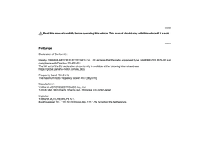 2
2 3
3 4
4 5
5 6
6 7
7 8
8 9
9 10
10 11
11 12
12 13
13 14
14 15
15 16
16 17
17 18
18 19
19 20
20 21
21 22
22 23
23 24
24 25
25 26
26 27
27 28
28 29
29 30
30 31
31 32
32 33
33 34
34 35
35 36
36 37
37 38
38 39
39 40
40 41
41 42
42 43
43 44
44 45
45 46
46 47
47 48
48 49
49 50
50 51
51 52
52 53
53 54
54 55
55 56
56 57
57 58
58 59
59 60
60 61
61 62
62 63
63 64
64 65
65 66
66 67
67 68
68 69
69 70
70 71
71 72
72 73
73 74
74 75
75 76
76 77
77 78
78 79
79 80
80 81
81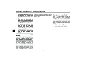 82
82 83
83 84
84 85
85 86
86 87
87 88
88 89
89 90
90 91
91 92
92 93
93 94
94 95
95 96
96 97
97 98
98 99
99 100
100 101
101 102
102 103
103 104
104 105
105 106
106 107
107 108
108 109
109
