Page 17 of 110
Description
2-3
2
EAU10431
Controls and instruments
1
2
4
6
5
7
8
3
1. Clutch lever (page 4-18)
2. Left handlebar switches (page 4-3)
3. Main switch/steering lock (page 4-2)
4. Instrument panel (page 4-5, 4-9)
5. Right handlebar switches (page 4-3)
6. Front brake fluid reservoir (page 7-20)
7. Throttle grip (page 7-25)
8. Brake lever (page 4-19)
UB7NE1E0.book Page 3 Friday, September 3, 2021 11:25 AM
Page 18 of 110

Special features
3-1
3
EAU91323
“D-MODE”“D-MODE” is an electronically con-
trolled engine performance system.
WARNING
EWA18440
Do not change the d rive mo de while
the vehicle is movin g.The “D-MODE” system consists of 4
different control maps which regulate
engine response and output, thus pro-
viding you with a selection of modes to
fit your preferences and the riding envi-
ronment.
D-MODE 1 - Sporty engine response
D-MODE 2 - Moderate engine re-
sponse
D-MODE 3 - Mild engine response
D-MODE 4 - Mild engine response and
limits engine outputTIP The current “D-MODE” setting is
shown in the MODE display. (See
page 4-11.)
The current “D-MODE” setting is
saved when the vehicle is turned
off.
The “D-MODE” is controlled by
the MODE switches, see page 4-4
for more information.
EAU91434
“TCS-MODE”This model is equipped with the trac-
tion control system, the slide control
system (SCS), and the lift control sys-
tem (LIF). These are grouped together
into “TCS-MODE”. “TCS-MODE” has
4 settings:
“TCS-MODE M” is customizable in the
settings MENU, see page 4-15.
Traction control system
The traction control system helps
maintain traction when accelerating. If
sensors detect that the rear wheel is
starting to slip (uncontrolled spinning),
the traction control system assists by
regulating engine power as needed un-
til traction is restored. The stability
MODE Tr a c -
tion
con- trol
sys- tem SCS LIF
TCS-MODE 1 111
TCS-MODE 2 222
TCS-MODE M 1, 2, 3 OFF,
1, 2, 3 OFF,
1, 2, 3
TCS-MODE OFF OFF OFF OFF
UB7NE1E0.book Page 1 Friday, September 3, 2021 11:25 AM
Page 19 of 110

Special features
3-2
3
control indicator light “ ” flashes to
let the rider know that traction control
has engaged.
This traction control system automati-
cally adjusts according to the vehicle’s
lean angle. To maximize acceleration,
when the vehicle is upright a lesser
amount of traction control is applied.
When cornering, a greater amount of
traction control is applied.
TIP
The traction control system may
engage when the vehicle travels
over a bump.
You may notice slight changes in
engine and exhaust sounds when
the traction control or other sys-
tems engage.
The traction control system can
only be turned off by setting “TCS-
MODE” to “OFF”, using the MODE
switches. See page 4-4 for more
information on “TCS-MODE”.
When “TCS-MODE” has been set
to “OFF”, the traction control sys-
tem, SCS and LIF systems are all
turned off together.
WARNING
EWA15433
The traction control system is not a
substitute for ri din g appropriately
for the con ditions. Traction control
cannot prevent loss of traction d ue
to excessive spee d when enterin g
turns, when acceleratin g har d at a
sharp lean an gle, or while brakin g,
an d cannot prevent front wheel slip-
pin g. As with any vehicle, approach
surfaces that may be slippery with
caution an d avoi d especially slip-
pery surfaces.When the vehicle power is on, the trac-
tion control system automatically turns
on. The traction control system can be turned on or off manually only when
the key is in the “ON” position and the
motorcycle is stopped.
TIP
the rear wheel if the motorcycle gets
stuck in mud, sand, or other soft sur-
faces.NOTICE
ECA16801
Use only the specifie
d tires. (See
pa ge 7-15.) Usin g different size d
tires will prevent the traction control
system from controllin g tire rotation
accurately.SCS
The slide control system regulates en-
gine power output when a sideward
slide is detected in the rear wheel. It
adjusts power output based on data
from the IMU (Inertial Measurement
Unit). This system supports the traction
control system to contribute to a
smoother ride.
Traction control system
UB7NE1E0.book Page 2 Friday, September 3, 2021 11:25 AM
Page 20 of 110

Special features
3-3
3LIF
The lift control system reduces the rate
at which the front wheel rises during
extreme acceleration, such as during
starts or out-of-corner exits. When
front-wheel lift is detected, engine
power is regulated to slow front-wheel
lift while still providing good accelera-
tion.
EAU91341
Quick shifterThe quick shifter allows for clutch le-
ver-less, electronically-assisted shift-
ing. When the sensor on the shift rod
detects the appropriate motion in the
shift pedal, engine power output is mo-
mentarily adjusted to allow for the gear
change to occur.
The quick shifter does not operate
when the clutch lever is pulled, there-
fore normal shifting can be done even
when the quick shifter is set to on.
Check the quick shifter indicator for
current status and usability informa-
tion.
Upshiftin
g con ditions
Vehicle speed of at least 20 km/h
(12 mi/h)
Engine speed of at least 2200
r/min
Accelerating (open throttle) Downshiftin
g con ditions
Vehicle speed of at least 20 km/h
(12 mi/h)
Engine speed of at least 2000
r/min
Engine speed sufficiently away
from red zone
Decelerating and throttle fully-
closed
TIPQS and QS can be individ-
ually set.
Shifting into or out of neutral must
be done using the clutch lever.
Quick shifter usab ility Indicator
Upshifting OK
Downshifting OK
Quick shifter cannot be used
Quick shifter turned off
UB7NE1E0.book Page 3 Friday, September 3, 2021 11:25 AM
Page 21 of 110
Special features
3-4
3
EAU91350
BCThe brake control system regulates hy-
draulic brake pressure for the front and
rear wheels when the brakes are ap-
plied and wheel lock is detected. This
system has two settings.
BC1 is standard ABS, which adjusts
brake pressure based on vehicle
speed and wheel speed data. BC1 is
designed to engage and maximize
braking when the vehicle is upright.
BC2 uses additional data from the IMU
to regulate applied brake power when
cornering to suppress lateral wheel
slip.
WARNING
EWA20891
The brake control system is not a
su bstitute for the use of proper ri d-
in g an d brakin g techniques. The
b rake control system cannot pre-
vent all loss of traction due to over-
b rakin g from excessive spee d, or
lateral wheel slip when brakin g on
slippery surfaces.
ABS
BC1/BC2 BC2 BC2
UB7NE1E0.book Page 4 Friday, September 3, 2021 11:25 AM
Page 22 of 110

Instrument and control functions
4-1
4
EAU1097B
Immo bilizer systemThis vehicle is equipped with an immo-
bilizer system to help prevent theft by
re-registering codes in the standard
keys. This system consists of the fol-
lowing:
a code re-registering key
two standard keys
a transponder (in each key)
an immobilizer unit (on the vehicle)
an ECU (on the vehicle)
a system indicator light (page 4-7) A
bout the keys
The code re-registering key is used to
register codes in each standard key.
Store the code re-registering key in a
safe place. Use a standard key for daily
operation.
When key replacement or re-register-
ing is necessary, bring the vehicle and
the code re-registering key along with
any remaining standard keys to a
Yamaha dealer to have them re-regis- tered.
TIP Keep the standard keys as well as
keys of other immobilizer systems
away from the code re-registering
key.
Keep other immobilizer system
keys away from the main switch
as they may cause signal interfer-
ence.NOTICE
ECA11823
DO NOT LOSE THE CODE RE-REG-
ISTERING KEY! CONTACT YOUR
DEALER IMMEDIATELY IF IT IS
LOST! If the cod e re-registering key
is lost, the existin g stan dar d keys can still b
e used to start the vehicle.
However, re gisterin g a new stan-
d ar d key is impossi ble. If all keys
have been lost or damag ed , the en-
tire immo bilizer system must be re-
placed . Therefore, han dle the keys
carefully. Do not su bmerse in water.
Do not expose to hi gh tempera-
tures.
Do not place near mag nets.
Do not place near items that
transmit electrical si gnals.
Do not han dle rou ghly.
Do not grin d or alter.
Do not disassem ble.
Do not put two keys of any im-
mo bilizer system on the same
key rin g.
1. Code re-registering key (red bow)
2. Standard keys (black bow)UB7NE1E0.book Page 1 Friday, September 3, 2021 11:25 AM
Page 23 of 110

Instrument and control functions
4-2
4
EAU10474
Main switch/steerin g lockThe main switch/steering lock controls
the ignition and lighting systems, and is
used to lock the steering. The various
positions are described below.TIPBe sure to use the standard key (black
bow) for regular use of the vehicle. To
minimize the risk of losing the code re-
registering key (red bow), keep it in a
safe place and only use it for code re-
registering.
EAU84035
ON
All electrical circuits are supplied with
power and the vehicle lights are turned
on. The engine can be started. The key
cannot be removed.TIP The headlight(s) will turn on when
the engine is started.
To prevent battery drain, do not
leave the key in the “ON” position
without the engine running.
EAU10664
OFF
All electrical systems are off. The key
can be removed.
WARNING
EWA10062
Never turn the key to “OFF” or
“LOCK” while the vehicle is movin g.
Otherwise the electrical systems will
b e switched off, which may result in
loss of control or an acci dent.
EAU73803
LOCK
The steering is locked and all electrical
systems are off. The key can be re-
moved.
To lock the steering1. Turn the handlebars all the way to
the left.
2. With the key in the “OFF” position, push the key in and turn it to
“LOCK”.
3. Remove the key.
ON
OFF
LOCK
1. PushK
2. TurnK12
UB7NE1E0.book Page 2 Friday, September 3, 2021 11:25 AM
Page 24 of 110
Instrument and control functions
4-3
4
TIPIf the steering will not lock, try turning
the handlebars back to the right slight-
ly.To unlock the steeringPush the key in and turn it to “OFF”.
EAU66055
Han dle bar switchesLeft
Right
1. Push.
2. Turn.12
1. Pass switch
 1
1 2
2 3
3 4
4 5
5 6
6 7
7 8
8 9
9 10
10 11
11 12
12 13
13 14
14 15
15 16
16 17
17 18
18 19
19 20
20 21
21 22
22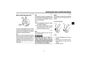 23
23 24
24 25
25 26
26 27
27 28
28 29
29 30
30 31
31 32
32 33
33 34
34 35
35 36
36 37
37 38
38 39
39 40
40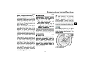 41
41 42
42 43
43 44
44 45
45 46
46 47
47 48
48 49
49 50
50 51
51 52
52 53
53 54
54 55
55 56
56 57
57 58
58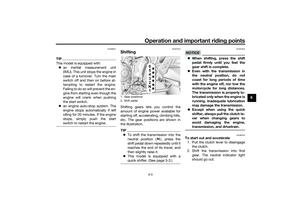 59
59 60
60 61
61 62
62 63
63 64
64 65
65 66
66 67
67 68
68 69
69 70
70 71
71 72
72 73
73 74
74 75
75 76
76 77
77 78
78 79
79 80
80 81
81 82
82 83
83 84
84 85
85 86
86 87
87 88
88 89
89 90
90 91
91 92
92 93
93 94
94 95
95 96
96 97
97 98
98 99
99 100
100 101
101 102
102 103
103 104
104 105
105 106
106 107
107 108
108 109
109
2. Left handlebar switches (page 4-3)
3. Main switch/steering lock (page 4-2)
4. Instrument panel (page")

