Page 33 of 110

Instrument and control functions
4-12
4
When unable to shift, QS is
white.
If the quick shifter function is turned
OFF, QS itself is not displayed.
The quick shifter functions can be
turned on or off in the setting MENU.
See page 4-15.
TIPThe upshift and downshift functions
are independent and can be activated
separately.
For more information on the quick
Settin
g menu icon “ ”
Choose this icon and push the wheel
switch to change the settings MENU
screen. (See page 4-14.)
Grip warmer in dicator (Option)
The grip warmers can be used when
the engine is running. There are 10
temperature levels. When activated,
the indicator will display the tempera-
ture level from 1 (lowest) to 10 (high-
est). To activate the grip warmer, use the
wheel switch to highlight the grip
warmer display with the cursor.
Press the wheel switch inward to se-
lect the grip warmer function.
Once selected, rotate the wheel switch
up and down to adjust the temperature
level.
Press the wheel switch inward to con-
firm the temperature level and exit the
grip warmer function.
NOTICE
ECA17932
Be sure to wear g loves when
using the grip warmers.
Do not use the grip warmers in
warm weather.
If the han dle bar grip or throttle
g rip becomes worn or d am-
a g ed , stop usin g the g rip warm-
ers an d replace the grips.The function of the wheel switch can
be locked into grip warmer mode by
pressing and holding the wheel switch
inward while the grip warmer indicator
is highlighted by the cursor. In this mode, the temperature levels
can be instantly adjusted by rotating
the wheel switch up/down.
To exit this mode and return the wheel
switch to its normal functionality, press
and hold the wheel switch inward.
TIPThe current grip warmer setting is
saved when the vehicle is turned off.Lap timer
This stopwatch function can be acti-
vated through the setting MENU. (See
page 4-14.)
Once activated, the vehicle information
display is replaced with:1. Lap count
2. Current lap time
3. Latest/Previous lap time
LAP
02
LATEST
00:12.3
4
00:3 0.23
2
1
3
UB7NE1E0.book Page 12 Friday, September 3, 2021 11:25 AM
Page 34 of 110

Instrument and control functions
4-13
4 To start the timer, press the pass
switch.
Each press of the pass switch will in-
crease the lap count by 1 and reset the
current lap timer.
To pause the lap timer, press the wheel
switch inward.
To unpause the timer, press the pass
switch and the timer will resume with-
out counting a new lap.
To exit the lap time mode, turn it off in
the settings MENU. (See page 4-14.)
TIP
The engine must be running to
start the lap timer.
The headlight will flash when the
pass switch is pressed.
Whenever the lap timer is paused,
it can be resumed using the pass
switch.Brake control icon “BC”
This icon is replaced by the auxiliary
system warning and coolant tempera-
ture warning indicators when they are
activated.
For more information on the BC sys-
tem see “BC” on page 3-4. Error mo
de warnin g “Err”
When an internal error occurs (e.g.,
communication with a system control-
ler has been cut off), the error mode
warning will appear as follows.
“Err” and “ ” indicator light indicates
an ECU error.
“Err” only indicates an ABS ECU error.
TIPDepending on the nature of the error,
the display may not function properly
and the traction control system set-
tings may be impossible to change.
Additionally, ABS may not function
properly. Use extra care when braking
and have a Yamaha dealer check the
vehicle immediately.Auxiliary system warnin g“”
This icon appears if a problem is de-
tected in a non-engine-related system.
Coolant temperature warnin g“”
This icon appears if the coolant tem-
perature reaches 116 °C (241 °F) or
higher. Stop the vehicle and turn off the
engine. Allow the engine to cool.
NOTICE
ECA10022
Do not continue to operate the en-
g ine if it is overheatin g.Oil pressure warnin g“”
This icon appears when the engine oil
pressure is low. When the vehicle is
first turned on, engine oil pressure has
yet to build, so this icon will come on
and stay on until the engine has been
started.TIPIf a malfunction is detected, the oil
pressure warning icon will flash repeat-
edly.NOTICE
ECA26410
Do not continue to operate the en-
g ine if the oil pressure is low.
UB7NE1E0.book Page 13 Friday, September 3, 2021 11:25 AM
Page 35 of 110

Instrument and control functions
4-14
4
EAU9145A
Settin gs MENUThe settings MENU screen contains
the following settings modules. Select
a module to make related settings
changes. Settin
gs MENU access an d opera-
tion
How to use the settings MENU:
Rotate the wheel switch up or down to
highlight items or increase/decrease
values and briefly press the wheel
switch inward to confirm the selection.
Press and hold the wheel switch until
the screen returns to the main display
to exit the MENU at any time.
TIP Certain settings menu screens
have an upward pointing triangle
mark item. Select the triangle
mark to save settings changes
and exit the current screen.
Should vehicle motion be detect-
ed, the screen will automatically
exit the settings MENU and return
to the main display.
To ensure that the desired settings
changes are saved, be sure to exit
each menu via the triangle mark (if
displayed). Exiting the settings
menu by pressing and holding the
wheel switch may not save set-
tings changes.
“Display Settin g”
This module allows you to switch the
lap time mode and tachometer color
mode ON/OFF.
When the lap time mode is selected,
the twin vehicle information displays
on the main screen will display a lap
timer and a lap counter. To exit the lap
time mode, the turn lap timer OFF in
the display setting module.
Mo dule Description
“Exit” Exit MENU and return the
main display
“Display Set-
ting” Switch lap time mode
on/off and adjust the ta-
chometer color
“Manual TCS
Setting” Adjust traction control sys-
tem/SCS/LIF settings for
the “TCS-MODE M”
“Vehicle Set-
ting” Adjust BC/quick shifter
settings
“Shift Indica-
tor” Turn the shift indicator
on/off and adjust tachom-
eter settings
“Maintenance” View and reset mainte-
nance intervals
Display S
etting
Exit
Manual TCS S ettingVehicle S ettingShift Indicator
km/h
MENU
Page 36 of 110

Instrument and control functions
4-15
4 To change the tachometer to color
mode, select ON.
“Manual TCS Settin
g”
This module allows you to customize
the “TCS-MODE M” which is accessi-
ble on the main display using the
MODE switches.
Traction control system
This model uses a variable traction
control system. For each setting level,
the further the vehicle is leaned over,
the greater the amount of traction con-
trol (system intervention) is applied.
There are 3 setting levels available for
the “TCS-MODE M”. Setting level 1 applies the least amount
of overall system intervention, while
setting level 3 applies the greatest
amount of overall traction control.
TIP
The traction control system can
only be turned on or off via the
main screen using the MODE
switches.
SCS and LIF can be turned off in-
dependently of traction control
system for “TCS-MODE M”.
When “TCS-MODE” has been set
to “OFF” on the main screen: trac-
tion control system, SCS and LIF
are all turned off together.SCSSCS can be set to OFF, 1, 2, and 3.
OFF turns the slide control system off,
setting level 1 provides the least
amount of system intervention, and
setting level 3 provides the greatest
amount of system intervention.
LIFLIF can be set to OFF, 1, 2, and 3. Setting level 1 provides the least
amount of system intervention and set-
ting 3 most strongly reduces the rate of
wheel lift.
OFF turns LIF off.
“Vehicle Setting
”
The vehicle setting module allows you
to adjust setting for the BC and quick
shifter.
TCS 1SC S 1LIF 1
km/h
Manual TCS Setting
BC SettingQS S etting
km/h
Vehicle Setting
UB7NE1E0.book Page 15 Friday, September 3, 2021 11:25 AM
Page 37 of 110

Instrument and control functions
4-16
4
BC
The brake control system has two set-
tings, BC1 and BC2. Select BC1 when
only standard ABS is desired. Select
BC2 to have the brake control system
further regulate brake pressure while
cornering to suppress lateral wheel
slip.TIPFor skilled riders and when riding at the
track, due to varying conditions, the
BC2 brake system may engage sooner
than expected relative to your desired
cornering speed or intended cornering
line.
Quick shifterThe quick shifter indicators are divided
into QS and QS sections. QS
and QS are not linked and can be in-
dependently turned on or off.
The quick shifter can be set to ON or
OFF.
OFF turns the respective upshift or
downshift function off, and the clutch
lever must then be used when shifting
in that direction.TIPIf the quick shifter setting cannot be
changed: turn the engine off with the
gear position set to neutral, then
change the setting.
“Shift In
dicator”
This module allows a custom shift indi-
cator to be set. When the engine r/min
(rotations per minute) are in the speci-
fied range, the gear indicator will flash.
This module has 3 options:
“IND Mode” - the shift indicator can be
turned ON/OFF
“IND Start” - the r/min at which the in-
dicator starts flashing can be chosen.
Once selected, rotate the wheel switch
up/down to increase or decrease the
r/min value by increments of 200 r/min.
“IND Start” is settable between 6000 -
12800 r/min.
“IND Stop” - the r/min at which the in-
dicator stops flashing can be chosen.
Once selected, rotate the wheel switch
up/down to increase or decrease the
km/h
BC Setting
BC
2
km/h
QS Setting
Q S ONQS ON
km/h
Shift Indicator
IND Mode ONIND Start 8000 r/minIND Stop 10000 r/min
UB7NE1E0.book Page 16 Friday, September 3, 2021 11:25 AM
Page 38 of 110

Instrument and control functions
4-17
4 r/min value by increments of 200 r/min.
“IND Stop” is settable between 6200 -
13000 r/min.
“Maintenance”
This module allows you to record the
distance traveled between engine oil
changes (use the OIL item), and for two
other items of your choice (use INTER-
VAL 1 and INTERVAL 2).
To reset a maintenance trip meter, se-
lect it and then press and hold the
wheel switch.
TIPMaintenance item names cannot be
changed.
“Unit”
This module allows you to switch the
display between metric and imperial
measurement units.
When using kilometers, the fuel con-
sumption units can be changed be-
tween “km/L” or “L/100km”. When
using miles, MPG will be available.
Temperature units can be switched
between Celsius and Fahrenheit. “Brig
htness”
This module allows you to adjust the
general brightness level of the display
screen.
Select the desired brightness level by
rotating the wheel switch, and then
press the wheel switch to fix the setting
and return to the top MENU screen.
“Clock”
OIL
INTERVAL 1INTERVAL 2 1000
km/h
km
1000
km
1000
km
Maintenance
km or mile
kmL/100km
Page 39 of 110

Instrument and control functions
4-18
4
This module allows you to set the
clock.
When the clock module is selected, the
hours will be highlighted.
Set the hours by rotating the wheel
switch. Push the switch to confirm and
highlight the minutes.
After confirming the minutes, you will
be returned to the top MENU screen.
“All Reset”
This module resets all settings items
(except the odometer and clock) to
their default or factory presets.
Select YES to reset all items. After se-
lecting YES, all items will be reset and
the screen will automatically return to
the top MENU screen.
EAU12823
Clutch leverTo disengage the drivetrain from the
engine, such as when shifting gears,
pull the clutch lever toward to the han-
dlebar. Release the lever to engage the
clutch and transmit power to the rear
wheel.TIPThe lever should be pulled rapidly and
released slowly for smooth shifting.
(See page 6-3.)
EAU83692
Shift pe
dalThe shift pedal is located on the left
side of the motorcycle. To shift the
transmission to a higher gear, move
the shift pedal up. To shift the trans-
mission to a lower gear, move the shift
pedal down. (See page 6-3.)
The shift rod is equipped with a shift
sensor, which is part of the quick shift-
er. The shift sensor reads up and down
movement, as well as the strength of
the input force when the shift pedal is
moved.
NOYES
km/h
All Reset
1. Clutch lever
1 1 1
1. Shift pedal
2. Shift rod
1 1 1
2 2
UB7NE1E0.book Page 18 Friday, September 3, 2021 11:25 AM
Page 40 of 110
Instrument and control functions
4-19
4
TIPTo prevent unintended shifts, the quick
shifter is programmed to ignore un-
clear input signals. Therefore, be sure
to shift using quick and sufficiently
forceful inputs.
EAU26827
Brake leverThe brake lever is located on the right
side of the handlebar. To apply the
front brake, pull the lever toward the
throttle grip.
The brake lever is equipped with a
brake lever position adjusting dial. To
adjust the distance between the brake
lever and the throttle grip, push the
brake lever away from the throttle grip
and rotate the adjusting dial. Make
sure the setting number on the adjust-
ing dial aligns with the match mark on
the brake lever.
EAU12944
Brake ped alThe brake pedal is located on the right
side of the motorcycle. To apply the
rear brake, press down on the brake
pedal.
1. Brake lever
2. Distance
3. Match mark
4. Adjusting dial
1
2
4
3
1. Brake pedal
111
UB7NE1E0.book Page 19 Friday, September 3, 2021 11:25 AM
 1
1 2
2 3
3 4
4 5
5 6
6 7
7 8
8 9
9 10
10 11
11 12
12 13
13 14
14 15
15 16
16 17
17 18
18 19
19 20
20 21
21 22
22 23
23 24
24 25
25 26
26 27
27 28
28 29
29 30
30 31
31 32
32 33
33 34
34 35
35 36
36 37
37 38
38 39
39 40
40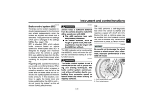 41
41 42
42 43
43 44
44 45
45 46
46 47
47 48
48 49
49 50
50 51
51 52
52 53
53 54
54 55
55 56
56 57
57 58
58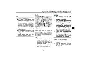 59
59 60
60 61
61 62
62 63
63 64
64 65
65 66
66 67
67 68
68 69
69 70
70 71
71 72
72 73
73 74
74 75
75 76
76 77
77 78
78 79
79 80
80 81
81 82
82 83
83 84
84 85
85 86
86 87
87 88
88 89
89 90
90 91
91 92
92 93
93 94
94 95
95 96
96 97
97 98
98 99
99 100
100 101
101 102
102 103
103 104
104 105
105 106
106 107
107 108
108 109
109