Page 121 of 211
Page 122 of 211

Keep the air intake slots in front of the windscreen free of snow, ice and leaves to ensure
heating and cooling is not impaired, and to prevent the windows from misting over.
Controls
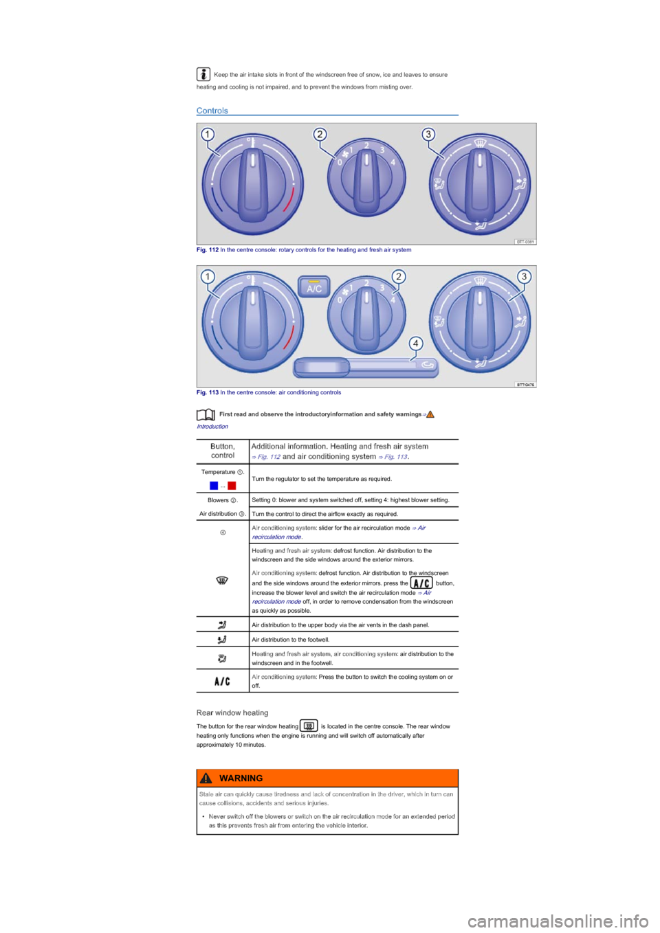
Fig. 112 In the centre console: rotary controls for the heating and fresh air system
Fig. 113 In the centre console: air conditioning controls
First read and observe the introductoryinformation and safety warnings⇒
Introduction
Button,
control
Additional information. Heating and fresh air system
⇒ Fig. 112 and air conditioning system ⇒ Fig. 113.
Temperature ①.
Turn the regulator to set the temperature as required.
...
Blowers ②.Setting 0: blower and system switched off, setting 4: highest blower setting.
Air distribution ③.Turn the control to direct the airflow exactly as required.
④Air conditioning system: slider for the air recirculation mode ⇒ Air
recirculation mode.
Heating and fresh air system: defrost function. Air distribution to the
windscreen and the side windows around the exterior mirrors.
Air conditioning system: defrost function. Air distribution to the windscreen
and the side windows around the exterior mirrors. press the button,
increase the blower level and switch the air recirculation mode ⇒ Air
recirculation mode off, in order to remove condensation from the windscreen
as quickly as possible.
Air distribution to the upper body via the air vents in the dash panel.
Air distribution to the footwell.
Heating and fresh air system, air conditioning system: air distribution to the
windscreen and in the footwell.
Air conditioning system: Press the button to switch the cooling system on or
off.
Rear window heating
The button for the rear window heating is located in the centre console. The rear window
heating only functions when the engine is running and will switch off automatically after
approximately 10 minutes.
Stale air can quickly cause tiredness and lack of concentration in the driver, which in turn can
cause collisions, accidents and serious injuries.
\f
Page 123 of 211
General information on the heating and fresh air system
First read and observe the introductoryinformation and safety warnings⇒
Introduction
The required interior temperature cannot be lower than the outside temperature as the heating and
fresh air system cannot cool or dehumidify the air.
Settings for optimal road visibility
\f
Page 124 of 211
Vents
The vents ⇒ Fig. 114① should be left open to ensure that the vehicle interior is sufficiently heated,
ventilated and cooled.
\f
Page 125 of 211
Page 126 of 211

Fig. 115 In the instrument cluster: variant A: fuel gauge for petrol, variant B: fuel gauge for petrol
Fig. 116 In the instrument cluster display: fuel gauge for petrol
First read and observe the introductoryinformation and safety warnings⇒
Introduction
The fuel gauge can vary according to the vehicle equipment level ⇒ Fig. 115 or ⇒ Fig. 116.
Lit upNeedle position
⇒ Fig. 115
Possible cause ⇒Solution
Red marking ①
Fuel tank nearly empty.
Reserve quantity is being used
⇒ Capacities.
Fill the tank with petrol
as soon as possible ⇒
.
Blue marking ②
Natural gas fuel tank nearly
empty.
Reserve quantity is being used.
Refuel with natural gas
as soon as possible ⇒
.
Flashes for
approximately
10 seconds
Position of the
bar ⇒ Fig. 116
Possible cause ⇒Solution
Reserve fuel
marking flashes for
approximately 10
seconds (four small
segmentsyf
Fuel tank nearly empty.
Reserve quantity is being used
⇒ Capacities.
Fill the tank as soon as
possible ⇒.
Several warning and indicator lamps will light up briefly as a functional check when the ignition is
switched on. They will switch off after a few seconds.
Natural gas engines
Things to note: if the vehicle is parked for an extended period directly after refuelling, it may well
occur that the pointer for the natural gas engine does not indicate the fuel level shown directly after
refuelling. This does not mean that there is a leak in the system but but rather that, for technical
reasons the pressure has been decreased in the natural gas tank.
The small arrow next to the petrol pump symbol ⇒ Fig. 115 in the display instrument shows
you the side of the vehicle on which the tank flap is located.
Only applies for vehicles with a fuel gauge in the instrument cluster ⇒ Fig. 115.
Only applies for vehicles with a fuel gauge in the instrument cluster display ⇒ Fig. 116.
Filling the tank with petrol
ayf
byf
Driving the vehicle when the fuel level is too low could lead to your vehicle breaking down in
traffic, accidents and serious injuries.
\f
Page 127 of 211
Fig. 117 Open tank flap with tank cap attached to the holder
First read and observe the introductoryinformation and safety warnings⇒
Introduction
Switch off the engine, ignition and the mobile telephone before filling the tank and leave them
switched off during the process.
Opening the tank cap
\f
Page 128 of 211
Switch off the engine, ignition and the mobile telephone before filling the tank and leave them
switched off during the process ⇒.
Please read and follow the instructions for the natural gas refuelling system.
The vehicle is not constructed for use with Liquefied Natural Gas (LNGyf ⇒. Before refilling with
natural gas check that you are using the correct fuel ⇒ Fuel.
Opening the tank cap
The gas filler neck is located under the tank flap next to the petrol filler neck.
\f