2022 TOYOTA YARIS CROSS inflation pressure
[x] Cancel search: inflation pressurePage 425 of 618

423
7
CV Owner's Manual_Europe_M52N20_en
7-2. Steps to take in an emergency
When trouble arises
21Temporarily store the bottle and
compressor in the luggage com-
partment.
22 To spread the liquid sealant
evenly within the tire, immedi-
ately drive safely for about 5 km
(3 miles) below 80 km/h (50
mph).
23 After driving for about 5 km (3
miles), stop your vehicle in a
safe place on a hard, flat sur-
face and connect the compres-
sor.
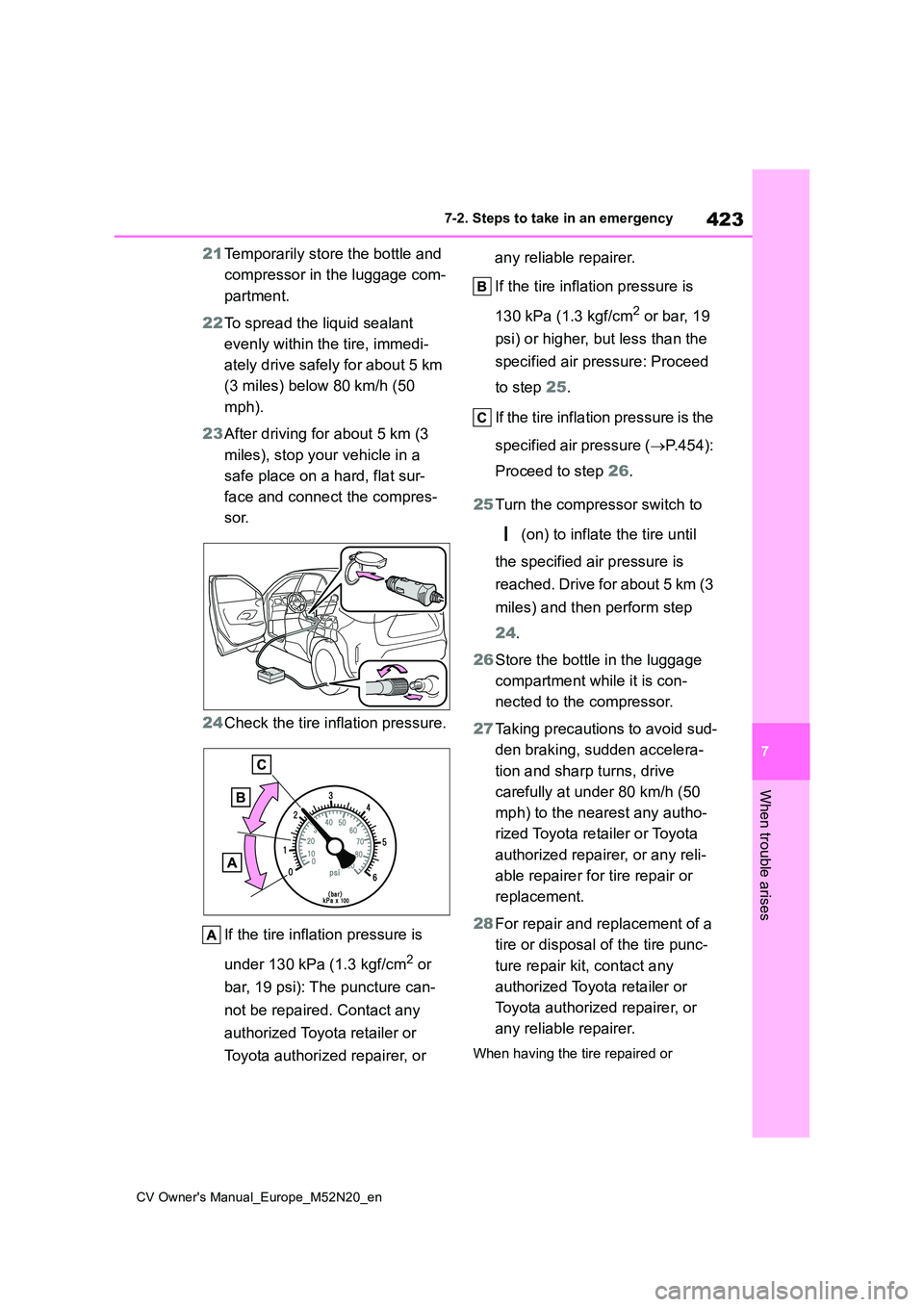
24 Check the tire inflation pressure.
If the tire inflation pressure is
under 130 kPa (1.3 kgf/cm2 or
bar, 19 psi): The puncture can-
not be repaired. Contact any
authorized Toyota retailer or
Toyota authorized repairer, or
any reliable repairer.
If the tire inflation pressure is
130 kPa (1.3 kgf/cm2 or bar, 19
psi) or higher, but less than the
specified air pressure: Proceed
to step 25.
If the tire inflation pressure is the
specified air pressure ( P.454):
Proceed to step 26.
25 Turn the compressor switch to
(on) to inflate the tire until
the specified air pressure is
reached. Drive for about 5 km (3
miles) and then perform step
24 .
26 Store the bottle in the luggage
compartment while it is con-
nected to the compressor.
27 Taking precautions to avoid sud-
den braking, sudden accelera-
tion and sharp turns, drive
carefully at under 80 km/h (50
mph) to the nearest any autho-
rized Toyota retailer or Toyota
authorized repairer, or any reli-
able repairer for tire repair or
replacement.
28 For repair and replacement of a
tire or disposal of the tire punc-
ture repair kit, contact any
authorized Toyota retailer or
Toyota authorized repairer, or
any reliable repairer.
When having the tire repaired or
Page 426 of 618

424
CV Owner's Manual_Europe_M52N20_en
7-2. Steps to take in an emergency
replaced, make sure to tell any autho-
rized Toyota retailer or Toyota autho- rized repairer, or any reliable repairer that the sealant is injected.
■If the tire is inflated to more than the specified air pressure
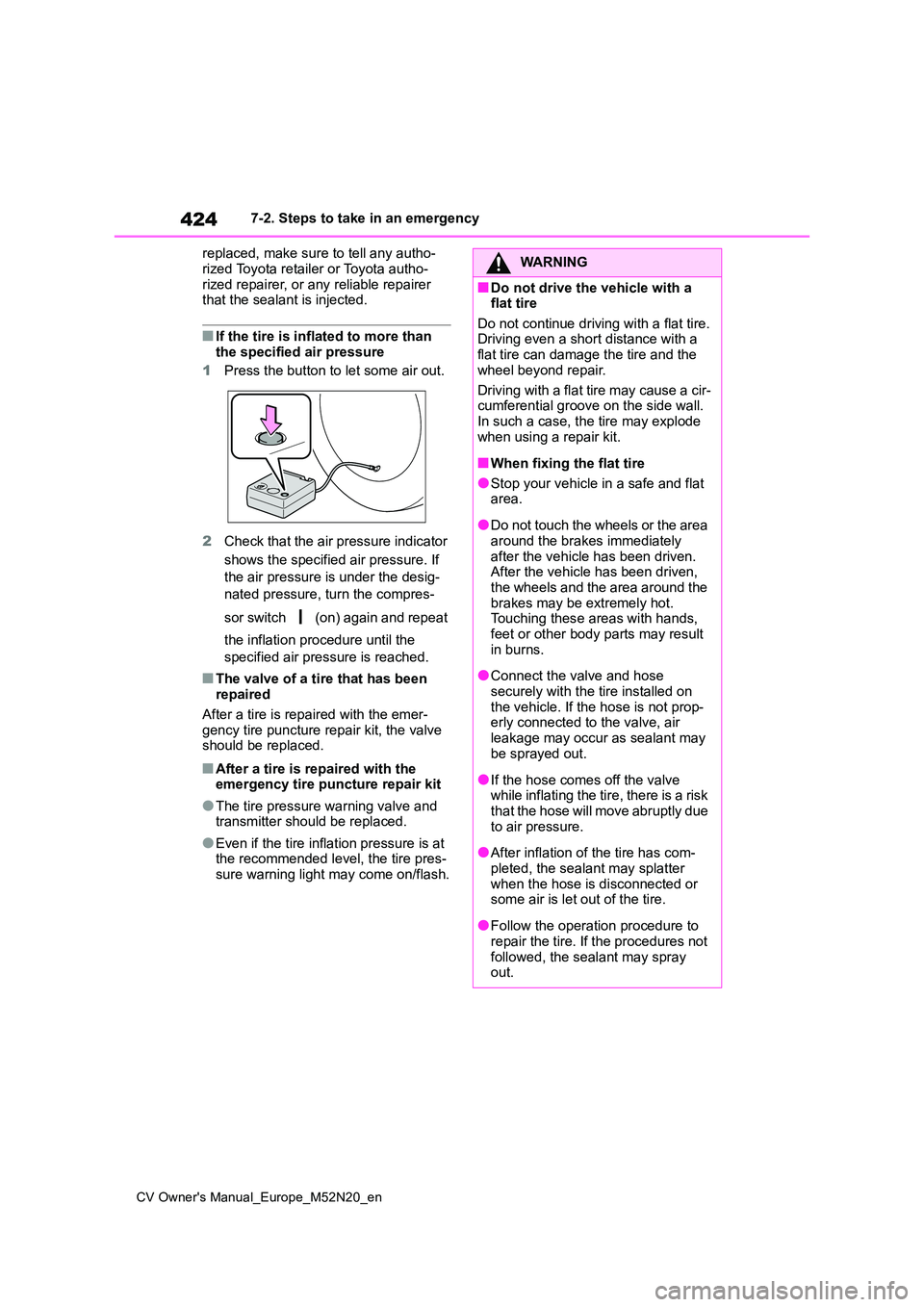
1 Press the button to let some air out.
2 Check that the air pressure indicator
shows the specified air pressure. If
the air pressure is under the desig-
nated pressure, turn the compres-
sor switch (on) again and repeat
the inflation procedure until the
specified air pressure is reached.
■The valve of a tire that has been repaired
After a tire is repaired with the emer-
gency tire puncture repair kit, the valve should be replaced.
■After a tire is repaired with the emergency tire puncture repair kit
●The tire pressure warning valve and transmitter should be replaced.
●Even if the tire inflation pressure is at the recommended level, the tire pres-
sure warning light may come on/flash.
WARNING
■Do not drive the vehicle with a flat tire
Do not continue driving with a flat tire. Driving even a short distance with a flat tire can damage the tire and the
wheel beyond repair.
Driving with a flat tire may cause a cir- cumferential groove on the side wall.
In such a case, the tire may explode when using a repair kit.
■When fixing the flat tire
●Stop your vehicle in a safe and flat area.
●Do not touch the wheels or the area around the brakes immediately
after the vehicle has been driven. After the vehicle has been driven, the wheels and the area around the
brakes may be extremely hot. Touching these areas with hands, feet or other body parts may result
in burns.
●Connect the valve and hose
securely with the tire installed on the vehicle. If the hose is not prop-erly connected to the valve, air
leakage may occur as sealant may be sprayed out.
●If the hose comes off the valve while inflating the tire, there is a risk that the hose will move abruptly due
to air pressure.
●After inflation of the tire has com-
pleted, the sealant may splatter when the hose is disconnected or some air is let out of the tire.
●Follow the operation procedure to repair the tire. If the procedures not
followed, the sealant may spray out.
Page 427 of 618

425
7
CV Owner's Manual_Europe_M52N20_en
7-2. Steps to take in an emergency
When trouble arises
WARNING
●Keep back from the tire while it is
being repaired, as there is a chance
of it bursting while the repair opera-
tion is being performed. If you
notice any cracks or deformation of
the tire, turn (off) the compres-
sor switch and stop the repair oper-
ation immediately.
●The repair kit may overheat if oper- ated for a long period of time. Do
not operate the repair kit continu- ously for more than 40 minutes.
●Parts of the repair kit become hot during operation. Be careful when handling the repair kit during and
after operation. Do not touch the metal part around the connecting area between the bottle and com-
pressor. It will be extremely hot.
●Do not attach the vehicle speed
warning sticker to an area other than the one indicated. If the sticker is attached to an area where an
SRS airbag is located, such as the pad of the steering wheel, it may prevent the SRS airbag from oper-
ating properly.
●To avoid risk of burst or severe
leakage, do not drop or damage the bottle. Visually inspect the bottle before use. Do not use a bottle with
shock, crack, scratch, leakage or any other damage. In such case, immediately replace.
■Driving to spread the liquid seal-
ant evenly
Observe the following precautions to reduce the risk of accidents.
Failing to do so may result in a loss of vehicle control and cause death or serious injury.
●Drive the vehicle carefully at a low speed. Be especially careful when
turning and cornering.
●If the vehicle does not drive straight or you feel a pull through the steer-ing wheel, stop the vehicle and
check the following.
• Tire condition. The tire may have
separated from the wheel.
• Tire inflation pressure. If the tire
inflation pressure is 130 kPa (1.3
kgf/cm2 or bar, 19 psi) or less, the tire may be severely damaged.
NOTICE
■When performing an emergency repair
●A tire should only be repaired with
the emergency tire puncture repair kit if the damage is caused by a sharp object such as nail or screw
passing through the tire tread. Do not remove the sharp object from the tire. Removing the object
may widen the opening and disena- ble emergency repair with the repair kit.
●The repair kit is not waterproof. Make sure that the repair kit is not
exposed to water, such as when it is being used in the rain.
●Do not put the repair kit directly onto dusty ground such as sand at the side of the road. If the repair kit
vacuums up dust etc., a malfunc- tion may occur.
●Do not turn the bottle upside down when using it, as doing so may cause damage to the compressor.
■Precautions for the emergency tire puncture repair kit
●The repair kit power source should be 12 V DC suitable for vehicle use. Do not connect the repair kit to any
other source.
Page 434 of 618

432
CV Owner's Manual_Europe_M52N20_en
7-2. Steps to take in an emergency
.
When replacing an aluminum wheel
with an aluminum wheel, turn the wheel
nuts until the washers come into
contact with the disc wheel .
3 Lower the vehicle.
4 Firmly tighten each wheel nut
two or three times in the order
shown in the illustration.
Tightening torque:
103 N•m (10.5 kgf•m, 76 ft•lbf)
5 Stow the flat tire, tire jack and all
tools.
■The full-size spare tire (if equipped)
●The full-size spare tire has a “Tempo- rary use only” label on the outer sur-
face of the wheel. Use the full-size spare tire temporarily, and only in an emergency.
●Make sure to check the tire inflation pressure of the full-size spare tire.
( P.454)
■The compact spare tire (if equipped)
●The compact spare tire is identified by the label “TEMPORARY USE ONLY” on the tire sidewall. Use the compact
spare tire temporarily, and only in an emergency.
●Make sure to check the tire inflation pressure of the compact spare tire. ( P.454)
■When the compact spare tire (if
equipped) is equipped
The vehicle becomes lower when driv- ing with the compact spare tire com-
pared to when driving with standard tires.
■When using the compact spare tire
(if equipped)
As the compact spare tire is not equipped with a tire pressure warning
valve and transmitter, low inflation pres- sure of the compact spare tire will not be indicated by the tire pressure warning
Page 456 of 618

454
CV Owner's Manual_Europe_M52N20_en
8-1. Specifications
*1: Minimum pedal clearance when depressed with a force of 300 N (31.0 kgf, 67.4
lbf) while the engine is running.
*2: Make sure to confirm that the brake warning light (yellow) doe s not illuminate. (If
the brake warning light illuminates, refer to P.81, 410)
16-inch tires
17-inch tires
Parking brake indicator*2
When pulling the parking brake switch for 1 to 2
seconds: comes on
When pushing the parking brake switch for 1 to
2 seconds: turns off
Fluid typeSAE J1704 or FMVSS No.116 DOT 4
Steering
Free playLess than 30 mm (1.2 in.)
Tires and wheels
Tire size205/65R16 95H
Tire inflation pressure
(Recommended cold tire
inflation pressure)
Front tire
230 kPa (2.3 kgf/cm2 or bar, 33 psi)
Rear tire
220 kPa (2.2 kgf/cm2 or bar, 32 psi)
Wheel size16 6 1/2J
Wheel nut torque103 N•m (10.5 kgf•m, 76 ft•lbf)
Tire size215/55R17 94V
Tire inflation pressure
(Recommended cold tire
inflation pressure)
Front tire
220 kPa (2.2 kgf/cm2 or bar, 32 psi)
Rear tire
200 kPa (2.0 kgf/cm2 or bar, 29 psi)
Wheel size17 7J
Wheel nut torque103 N•m (10.5 kgf•m, 76 ft•lbf)
Page 457 of 618

455
8
CV Owner's Manual_Europe_M52N20_en
8-1. Specifications
Vehicle specifications
18-inch tires
Compact spare tire (if equipped)
*: If equipped
A: HIR2 halogen bulbs
B: Wedge base bulbs (amber)
C: Wedge base bulbs (clear)
Tire size215/50R18 92V
Tire inflation pressure
(Recommended cold tire
inflation pressure)
Front tire
220 kPa (2.2 kgf/cm2 or bar, 32 psi)
Rear tire
200 kPa (2.0 kgf/cm2 or bar, 29 psi)
Wheel size18 7J
Wheel nut torque103 N•m (10.5 kgf•m, 76 ft•lbf)
Tire sizeT145/90D16 106M
Tire inflation pressure
(Recommended cold tire
inflation pressure)
420 kPa (4.2 kgf/cm2 or bar, 60 psi)
Wheel size16 4T
Wheel nut torque103 N•m (10.5 kgf•m, 76 ft•lbf)
Light bulbs
Light bulbsWTyp e
Exterior
Halogen headlights (bulb type)55A
Front turn signal lights (bulb type)21B
Rear turn signal lights (bulb type)21B
Back up light (bulb type)16C
License plate light5C
Interior
Vanity lights*8C
Interior lights/personal lights5C
Luggage compartment light5C
Page 469 of 618

467
8
CV Owner's Manual_Europe_M52N20_en
8-3. Initialization
Vehicle specifications
8- 3. In it ia li za ti on
*: If equipped
Items to initialize
The following items must be initialized for normal system operation
after such cases as the battery being reconnected, or maintenan ce
being performed on the vehicle:
List of items to initialize
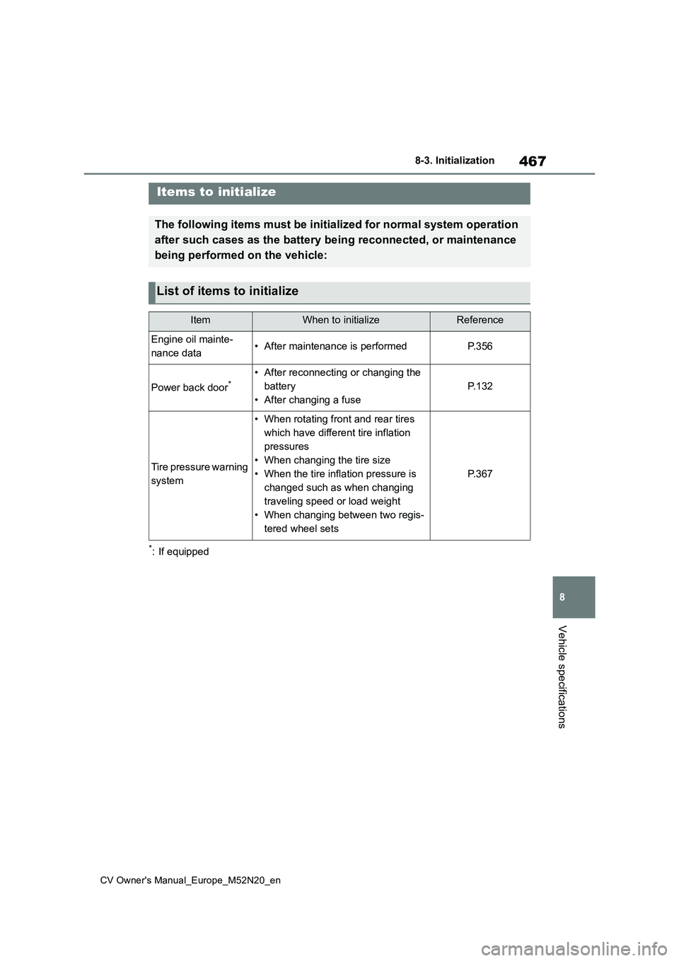
ItemWhen to initializeReference
Engine oil mainte-
nance data• After maintenance is performedP. 3 5 6
Power back door*• After reconnecting or changing the
battery
• After changing a fuse
P. 1 3 2
Tire pressure warning
system
• When rotating front and rear tires
which have different tire inflation
pressures
• When changing the tire size
• When the tire inflation pressure is
changed such as when changing
traveling speed or load weight
• When changing between two regis-
tered wheel sets
P. 3 6 7
Page 484 of 618

482
CV Owner's Manual_Europe_M52N20_en
Alphabetical Index
Secondary Collision Brake .......... 301
Sensor
Automatic headlight system ....... 193
Automatic High Beam system .... 201
BSM (Blind Spot Monitor) .......... 272
Inside rear view mirror ............... 150
LTA (Lane Tracing Assist) .......... 228
Parking Support Brake function
(static objects) ......................... 277
Radar sensor ..................... 212, 273
Rain-sensing windshield wipers . 206
RCTA (Rear Crossing Traffic Alert)
................................................. 284
Toyota parking assist-sensor ..... 277
Shift lever
If the shift lever cannot be shifted
from P ...................................... 180
Manual transmission .................. 183
Multidrive.................................... 179
Shift lock system .......................... 180
Side airbags .................................... 38
Side mirrors
Adjustment ................................. 150
BSM (Blind Spot Monitor) .......... 272
Folding ....................................... 151
RCTA (Rear Crossing Traffic Alert)
................................................. 284
Side turn signal lights .................. 186
Replacing light bulbs .................. 387
Turn signal lever ........................ 186
Side windows ................................ 153
Smart entry & start system .......... 136
Antenna location ........................ 136
Entry functions ................... 119, 125
Starting the engine ..................... 174
Snow tires ..................................... 307
Spare tire ....................................... 426
Inflation pressure ....................... 454
Storage location ......................... 427
Spark plug ..................................... 452
Specifications ............................... 448
Speed limiter ................................. 261
Warning message ...................... 262
Speedometer ............................. 85, 89
Steering lock
Column lock release........... 173, 175
Steering lock system warning mes-
sage ......................................... 175
Steering wheel
Adjustment ................................. 148
Audio switches ........................... 338
Heated steering wheel ............... 322
Meter control switches .........95, 101
Stop & Start system...................... 267
Function ..................................... 267
System information display ..99, 105
Warning light .............................. 407
Stop & Start system information dis-
play ........................................99, 105
Stop lights
Emergency brake signal............. 301
Replacing light bulbs ..................387
Storage features ........................... 326
Stuck
If the vehicle becomes stuck ...... 444
Sun visors ..................................... 337
Switches
Activating the Adaptive High-beam
System ..................................... 198
Airbag manual on-off switch ......... 47
Audio remote control switches ... 338
Automatic High Beam system .... 201
Brake Hold switch ...................... 190
Display change button............ 87, 92
Door lock switches ..................... 122
Driving mode select switch......... 299
Dynamic radar cruise control switch
................................................. 250
Dynamic radar cruise control with
full-speed range switch ............238
Emergency flashers switch ........ 394
Engine switch .....................173, 174