Page 357 of 618

355
6
CV Owner's Manual_Europe_M52N20_en
6-3. Do-it-yourself maintenance
Maintenance and care
■Checking the engine oil
1 Park the vehicle on level
ground. After warming up the
engine and turning it off, wait
more than 5 minutes for the oil
to drain back into the bottom of
the engine.
2 Holding a rag under the end,
pull the dipstick out.
3 Wipe the dipstick clean.
4 Reinsert the dipstick fully.
5 Holding a rag under the end,
pull the dipstick out and check
the oil level.
Low
Normal
Excessive
The shape of the dipstick may differ
depending on the type of vehicle or
engine.
6 Wipe the dipstick and reinsert it
fully.
■Checking the oil type and pre-
paring the item needed
Make sure to check the oil type and
prepare the items needed before
adding oil.
Engine oil selection
P.450
Oil quantity (Low Full)
1.5 L (1.6 qt., 1.3 Imp. qt.)
Item
Clean funnel
■Adding engine oil
If the oil level is below or near the
low level mark, add engine oil of the
same type as that already in the
engine.
1 Remove the oil filler cap by turn-
ing it counterclockwise.
2 Add engine oil slowly, checking
the dipstick.
3 Install the oil filler cap by turning
it clockwise.
■Engine oil consumption
A certain amount of engine oil will be
Page 361 of 618

359
6
CV Owner's Manual_Europe_M52N20_en
6-3. Do-it-yourself maintenance
Maintenance and care
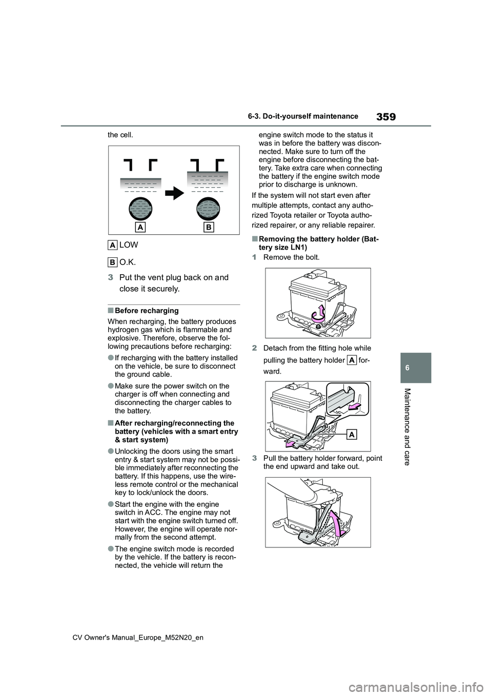
the cell.
LOW
O.K.
3 Put the vent plug back on and
close it securely.
■Before recharging
When recharging, the battery produces hydrogen gas which is flammable and explosive. Therefore, observe the fol-
lowing precautions before recharging:
●If recharging with the battery installed
on the vehicle, be sure to disconnect the ground cable.
●Make sure the power switch on the charger is off when connecting and
disconnecting the charger cables to the battery.
■After recharging/reconnecting the battery (vehicles with a smart entry
& start system)
●Unlocking the doors using the smart
entry & start system may not be possi- ble immediately after reconnecting the battery. If this happens, use the wire-
less remote control or the mechanical key to lock/unlock the doors.
●Start the engine with the engine switch in ACC. The engine may not start with the engine switch turned off.
However, the engine will operate nor- mally from the second attempt.
●The engine switch mode is recorded by the vehicle. If the battery is recon-nected, the vehicle will return the
engine switch mode to the status it
was in before the battery was discon- nected. Make sure to turn off the engine before disconnecting the bat-
tery. Take extra care when connecting the battery if the engine switch mode prior to discharge is unknown.
If the system will not start even after
multiple attempts, contact any autho-
rized Toyota retailer or Toyota autho-
rized repairer, or any reliable repairer.
■Removing the battery holder (Bat-
tery size LN1)
1 Remove the bolt.
2 Detach from the fitting hole while
pulling the battery holder for-
ward.
3 Pull the battery holder forward, point the end upward and take out.
Page 379 of 618

377
6
CV Owner's Manual_Europe_M52N20_en
6-3. Do-it-yourself maintenance
Maintenance and care
4Pull out the glove box and dis-
connect the lower claws.
5 Unlock the filter cover ( ), pull
the filter cover out of the claws
( ), and remove the filter
cover.
6 Remove the filter.
7 Replace the air conditioning fil-
ter with a new one.
The “ UP” marks shown on the filter
and the filter case should be pointing
up.
■Checking interval
Inspect and replace the air conditioning filter according to the maintenance schedule. In dusty areas or areas with
heavy traffic flow, early replacement may be required. (For scheduled main-tenance information, please refer to the
“Toyota Service Booklet” or “Toyota War- ranty Booklet”.)
■If air flow from the vents decreases dramatically
The filter may be clogged. Check the fil- ter and replace if necessary.
NOTICE
■When using the air conditioning system
Make sure that a filter is always
installed. Using the air conditioning system without a filter may cause damage to
the system.
Page 382 of 618

380
CV Owner's Manual_Europe_M52N20_en
6-3. Do-it-yourself maintenance
6Operate the or switch
and check that the doors can be
locked/unlocked.
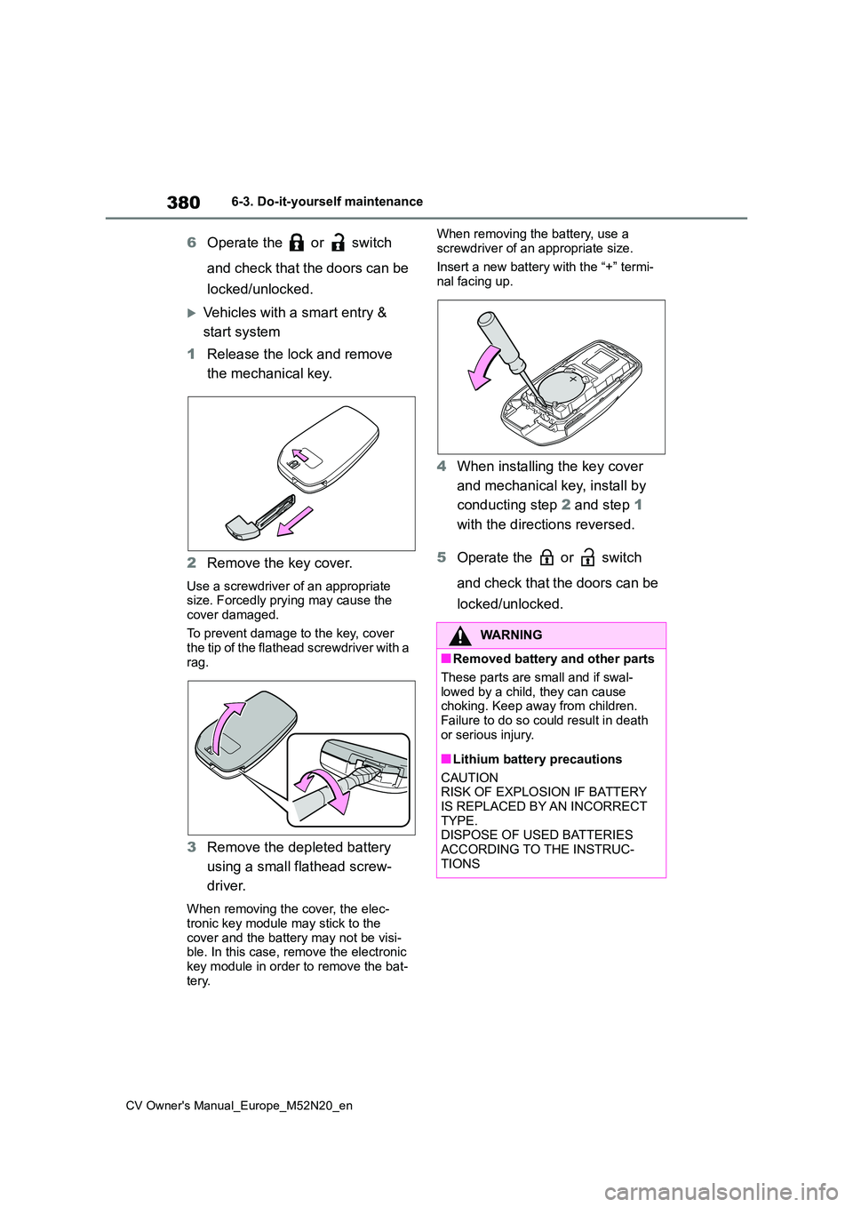
Vehicles with a smart entry &
start system
1 Release the lock and remove
the mechanical key.
2 Remove the key cover.
Use a screwdriver of an appropriate size. Forcedly prying may cause the
cover damaged.
To prevent damage to the key, cover the tip of the flathead screwdriver with a
rag.
3 Remove the depleted battery
using a small flathead screw-
driver.
When removing the cover, the elec- tronic key module may stick to the
cover and the battery may not be visi- ble. In this case, remove the electronic key module in order to remove the bat-
tery.
When removing the battery, use a
screwdriver of an appropriate size.
Insert a new battery with the “+” termi- nal facing up.
4 When installing the key cover
and mechanical key, install by
conducting step 2 and step 1
with the directions reversed.
5 Operate the or switch
and check that the doors can be
locked/unlocked.
WARNING
■Removed battery and other parts
These parts are small and if swal-
lowed by a child, they can cause choking. Keep away from children.
Failure to do so could result in death or serious injury.
■Lithium battery precautions
CAUTION RISK OF EXPLOSION IF BATTERY
IS REPLACED BY AN INCORRECT TYPE.DISPOSE OF USED BATTERIES
ACCORDING TO THE INSTRUC- TIONS
Page 384 of 618
382
CV Owner's Manual_Europe_M52N20_en
6-3. Do-it-yourself maintenance
Under the driver’s side instru-
ment panel (left-hand drive vehi-
cles)
Remove the lid.
Make sure to push the claw when
removing/installing the lid.
Under the passenger’s side
instrument panel (right-hand
drive vehicles)
• Vehicles without a footwell lights
Remove the cover and then remove the
lid.
Make sure to push the claw when
removing/installing the lid.
• Vehicles with a footwell lights
Remove the cover.
Rotate the cover 90 degrees clockwise.
Page 389 of 618

387
6
CV Owner's Manual_Europe_M52N20_en
6-3. Do-it-yourself maintenance
Maintenance and care
■LED light bulbs
The lights other than the following lights
each consist of a number of LEDs. If any of the LEDs burn out, take your vehicle to any authorized Toyota retailer or
Toyota authorized repairer, or any reli- able repairer to have the light replaced.
●Headlights (bulb type)
●Front turn signal lights (bulb type)
●Rear turn signal lights (bulb type)
●License plate lights
●Back-up light (bulb type)
■Condensation build-up on the
inside of the lens
Temporary condensation build-up on the inside of the headlight lens does not
indicate a malfunction. Contact any authorized Toyota retailer or Toyota authorized repairer, or any reliable
repairer for more information in the fol- lowing situations:
●Large drops of water have built up on the inside of the lens.
●Water has built up inside the head-light.
■When replacing light bulbs
P. 3 8 4
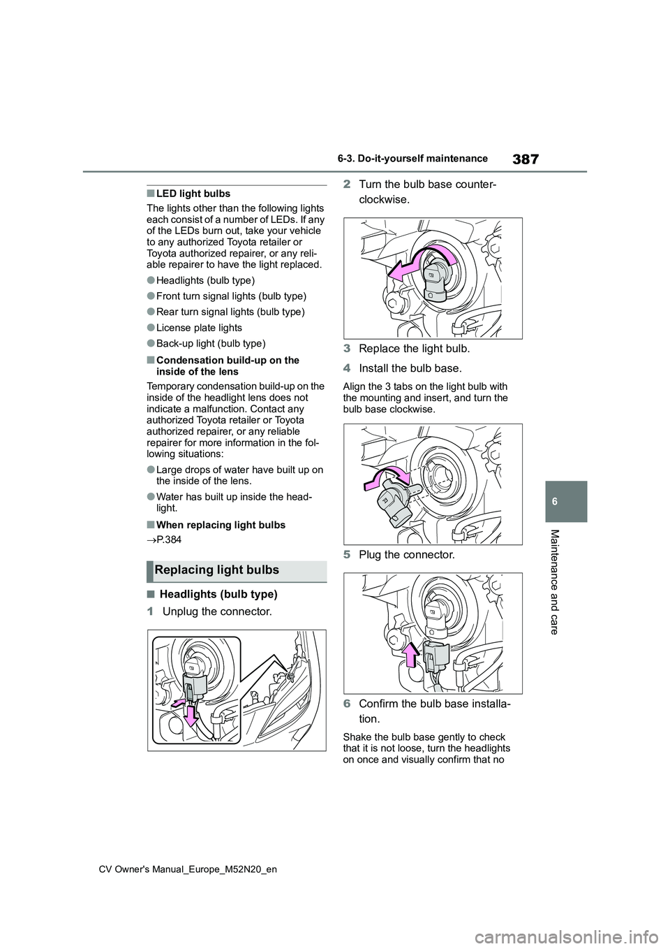
■Headlights (bulb type)
1 Unplug the connector.
2 Turn the bulb base counter-
clockwise.
3 Replace the light bulb.
4 Install the bulb base.
Align the 3 tabs on the light bulb with the mounting and insert, and turn the
bulb base clockwise.
5 Plug the connector.
6 Confirm the bulb base installa-
tion.
Shake the bulb base gently to check that it is not loose, turn the headlights
on once and visually confirm that no
Replacing light bulbs
Page 390 of 618
388
CV Owner's Manual_Europe_M52N20_en
6-3. Do-it-yourself maintenance
light is leaking through the mounting.
■Front turn signal lights (bulb
type)
1 Turn the bulb base counter-
clockwise.
2 Remove the light bulb.
3 When installing, reverse the
steps listed.
■Rear turn signal lights (bulb
type)
1 Open the back door.
2 Remove the 2 bolts and pull the
lamp assembly toward the rear
of the vehicle to remove it.
3 Turn the bulb base counter-
clockwise.
4 Remove the light bulb.
5 When installing the light bulb,
install by conducting 3 and 4
with the directions reversed.
6 Install the lamp assembly.
Align the guides and pins on the
lamp assembly with the mounting when
Page 392 of 618
390
CV Owner's Manual_Europe_M52N20_en
6-3. Do-it-yourself maintenance
2Remove the light bulb.
3 Install a new light bulb.
4 Install the lens.
1 Fit the lens into either the right
or left fitting portion.
2 Push the lens into place.
After installation, confirm that the lens is
properly installed by gently pulling it.
Fitting portion
■Back-up light (bulb type)
1 Open the back door and remove
the cover.
Press down on the notch on the cover
and remove the cover.
It is recommended for safeguarding to wrap the tip of the screwdriver with a
cloth, etc., in order to prevent scratches to the vehicle.
The back-up light (bulb type) position
will differ for right-hand drive vehicles. ( P.386)
2Turn the bulb base counter-
clockwise.