2022 TOYOTA TUNDRA HYBRID ECO mode
[x] Cancel search: ECO modePage 26 of 618
261-1. For safe use
Owners Manual_USA_M0C031_en
1-1.For safe use
Use only floor mats designed
specifically for vehicles of the
same model and model year as
your vehicle. Fix them securely
in place onto the carpet.
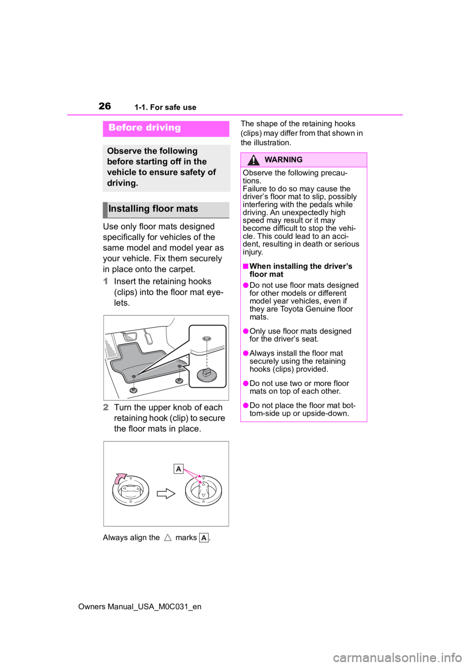
1Insert the retaining hooks
(clips) into the floor mat eye-
lets.
2 Turn the upper knob of each
retaining hook (clip) to secure
the floor mats in place.
Always align the marks . The shape of the retaining hooks
(clips) may differ from that shown in
the illustration.
Before driving
Observe the following
before starting off in the
vehicle to ensure safety of
driving.
Installing floor mats
WARNING
Observe the following precau-
tions.
Failure to do so may cause the
driver’s floor mat to slip, possibly
interfering with t
he pedals while
driving. An unexpectedly high
speed may result or it may
become difficult to stop the vehi-
cle. This could lead to an acci-
dent, resulting in death or serious
injury.
■When installing the driver’s
floor mat
●Do not use floor mats designed
for other models or different
model year vehicles, even if
they are Toyota Genuine floor
mats.
●Only use floor mats designed
for the driver’s seat.
●Always install the floor mat
securely using the retaining
hooks (clips) provided.
●Do not use two or more floor
mats on top of each other.
●Do not place the floor mat bot-
tom-side up or upside-down.
Page 67 of 618
671-2. Child safety
Owners Manual_USA_M0C031_en
1
For safety and security
WARNING
●When installing a child restraint
system in the rear center seat,
adjust both seat cushions to the
same position and align both
seatbacks at the same angle.
Otherwise, the child restraint
system cannot be securely
restrained and t his may cause
death or serious injuries in the
event of sudden braking, sud-
den swerving or an accident.
●If the seat is adjusted, reconfirm
the security of the child restraint
system.
■When installing a booster
seat
To prevent the belt from going into
ALR lock mode, do not fully
extend the shoulder belt. ALR
mode causes the belt to tighten
only. This could cause injury or
discomfort to the child. ( P.31,
33)
■Do not use a seat belt
extender
If a seat belt extender is used
when installing a child restraint
system, the seat belt will not
securely hold the child restraint
system, which could cause death
or serious injury to the child or
other passengers in the event of
sudden braking, sudden swerv-
ing or an accident.
Page 89 of 618
892-1. Instrument cluster
Owners Manual_USA_M0C031_en
2
Vehicle status information and indicators
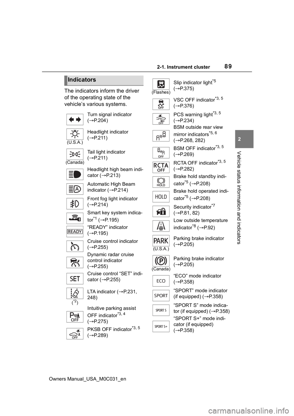
The indicators inform the driver
of the operating state of the
vehicle’s various systems.
Indicators
Turn signal indicator
( P.204)
(U.S.A.)
Headlight indicator
( P.211)
(Canada)
Tail light indicator
( P.211)
Headlight high beam indi-
cator ( P.213)
Automatic High Beam
indicator ( P.214)
Front fog light indicator
( P.214)
Smart key system indica-
tor
*1 ( P.195)
“READY” indicator
( P.195)
Cruise control indicator
( P.255)
Dynamic radar cruise
control indicator
( P.255)
Cruise control “SET” indi-
cator ( P.255)
(*2)
LTA indicator ( P.231,
248)
Intuitive parking assist
OFF indicator
*3, 4
( P.275)
PKSB OFF indicator
*3, 5
( P.289)
(Flashes)
Slip indicator light*5
( P.375)
VSC OFF indicator
*3, 5
( P.376)
PCS warning light
*3, 5
( P.234)
BSM outside rear view
mirror indicators
*5, 6
( P.268, 282)
BSM OFF indicator
*3, 5
( P.269)
RCTA OFF indicator
*3, 5
( P.282)
Brake hold standby indi-
cator
*5 ( P.208)
Brake hold operated indi-
cator
*5 ( P.208)
Security indicator
*7
( P.81, 82)
Low outside temperature
indicator
*8 ( P. 9 2 )
(U.S.A.)
Parking brake indicator
( P.205)
(Canada)
Parking brake indicator
( P.205)
“ECO” mode indicator
( P.358)
“SPORT” mode indicator
(if equipped) ( P.358)
“SPORT S” mode indica-
tor (if equipped) ( P.358)
“SPORT S+” mode indi-
cator (if equipped)
( P.358)
Page 90 of 618
902-1. Instrument cluster
Owners Manual_USA_M0C031_en
*1: This light illuminates on the multi-information display with a
message.
*2: Depending on the operating con-ditions of the system, the color
and state (illuminat ed/blinking) of
the indicator change.
*3: The light comes on when the system is turned off.
*4: Intuitive parking assist OFF indi-cator turns on wh en the power
switch is turned t o ON while the
Intuitive parking assist function is
on. It will turn off after a few sec-
onds.
*5: These lights tu rn on when the
power switch is turned to ON to
indicate that a system check is
being performed. They will turn
off after the hybrid system is
started, or after a few seconds.
There may be a malfunction in a
system if the lights do not turn
on, or turn off. Have the vehicle
inspected by your Toyota dealer.
*6: This light illuminates on the out- side rear view mirrors.
*7: This light illuminates on the over-head console.
*8: When the outside temperature is approximately 37°F (3°C) or
lower, the indicator will flash for
approximately 10 seconds, then
stay on.
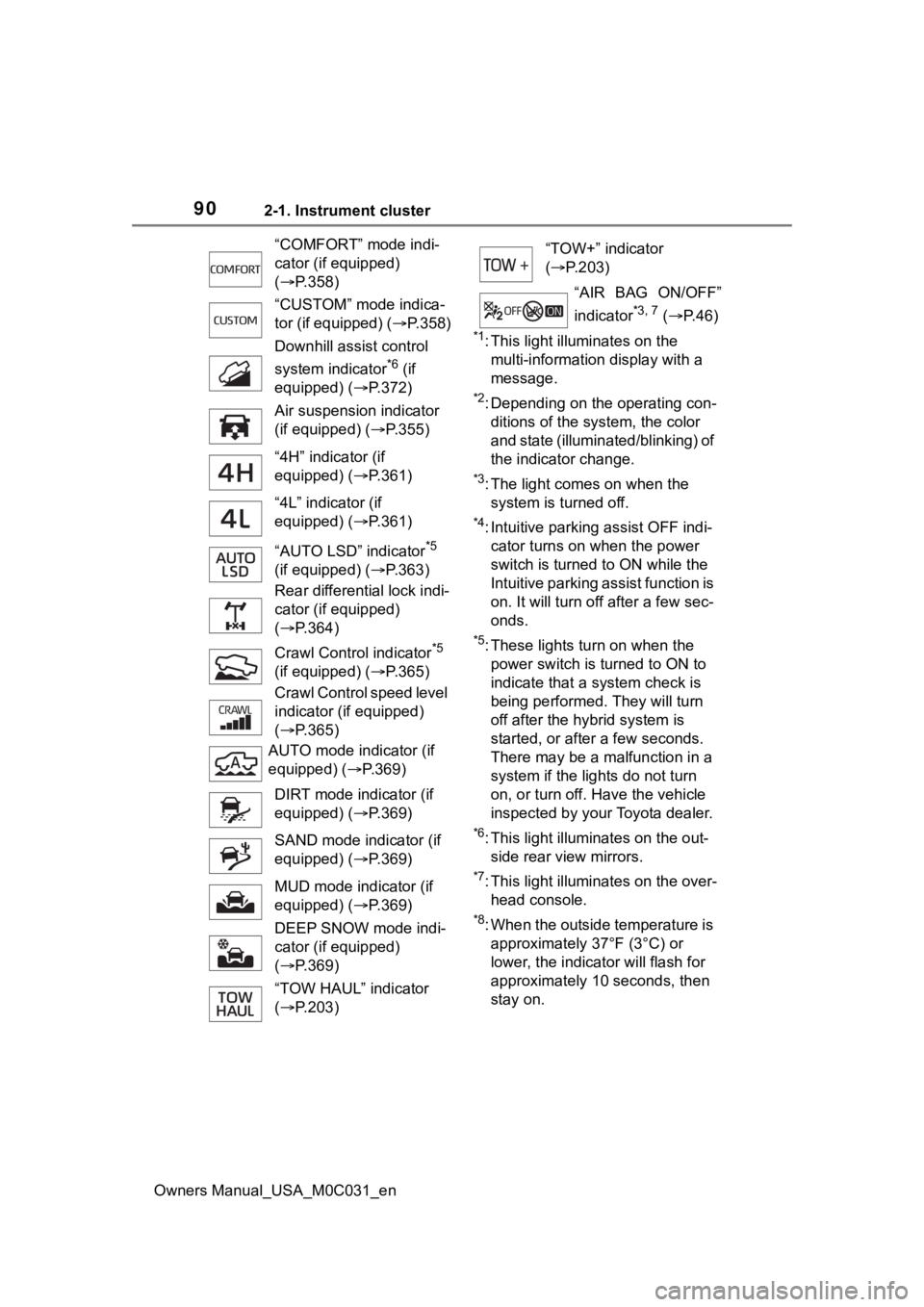
“COMFORT” mode indi-
cator (if equipped)
(
P.358)
“CUSTOM” mode indica-
tor (if equipped) ( P.358)
Downhill assist control
system indicator
*6 (if
equipped) ( P.372)
Air suspension indicator
(if equipped) ( P.355)
“4H” indicator (if
equipped) ( P.361)
“4L” indicator (if
equipped) ( P.361)
“AUTO LSD” indicator
*5
(if equipped) ( P.363)
Rear differential lock indi-
cator (if equipped)
( P.364)
Crawl Contro l indicator
*5
(if equipped) ( P.365)
Crawl Control speed level
indicator (if equipped)
( P.365)
AUTO mode indicator (if
equipped) ( P.369)
DIRT mode indicator (if
equipped) ( P.369)
SAND mode indicator (if
equipped) ( P.369)
MUD mode indicator (if
equipped) ( P.369)
DEEP SNOW mode indi-
cator (if equipped)
( P.369)
“TOW HAUL” indicator
( P.203)
“TOW+” indicator
( P.203)
“AIR BAG ON/OFF”
indicator
*3, 7 ( P. 4 6 )
Page 110 of 618
1103-1. Key information
Owners Manual_USA_M0C031_en
3-1.Key information
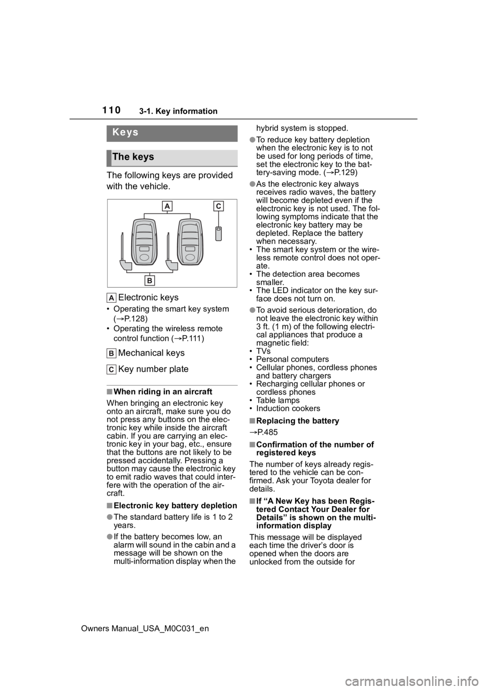
The following keys are provided
with the vehicle.Electronic keys
• Operating the smart key system ( P.128)
• Operating the wireless remote control function ( P. 111 )
Mechanical keys
Key number plate
■When riding in an aircraft
When bringing an electronic key
onto an aircraft, make sure you do
not press any buttons on the elec-
tronic key while inside the aircraft
cabin. If you are carrying an elec-
tronic key in your bag, etc., ensure
that the buttons are not likely to be
pressed accidentally. Pressing a
button may cause the electronic key
to emit radio waves that could inter-
fere with the oper ation of the air-
craft.
■Electronic key battery depletion
●The standard battery life is 1 to 2
years.
●If the battery becomes low, an
alarm will sound in the cabin and a
message will be s hown on the
multi-information display when the hybrid system is stopped.
●To reduce key battery depletion
when the electronic key is to not
be used for long periods of time,
set the electronic key to the bat-
tery-saving mode. (
P.129)
●As the electronic key always
receives radio waves, the battery
will become depleted even if the
electronic key is not used. The fol-
lowing symptoms indicate that the
electronic key battery may be
depleted. Replace the battery
when necessary.
• The smart key system or the wire- less remote contro l does not oper-
ate.
• The detection area becomes smaller.
• The LED indicator on the key sur- face does not turn on.
●To avoid serious deterioration, do
not leave the electronic key within
3 ft. (1 m) of the following electri-
cal appliances that produce a
magnetic field:
•TVs
• Personal computers
• Cellular phones, cordless phones and battery chargers
• Recharging cellular phones or cordless phones
• Table lamps
• Induction cookers
■Replacing the battery
P.485
■Confirmation of the number of
registered keys
The number of keys already regis-
tered to the vehi cle can be con-
firmed. Ask your Toyota dealer for
details.
■If “A New Key has been Regis-
tered Contact Your Dealer for
Details” is shown on the multi-
information display
This message will be displayed
each time the driver’s door is
opened when the doors are
unlocked from the outside for
Keys
The keys
Page 112 of 618
1123-1. Key information
Owners Manual_USA_M0C031_en
■Theft deterrent panic mode
When is pressed for longer
than about one second, an alarm
will sound intermittently and the
vehicle lights will f lash to deter any
person from trying to break into or
damage your vehicle.
To stop the alarm, press any button
on the electronic key.
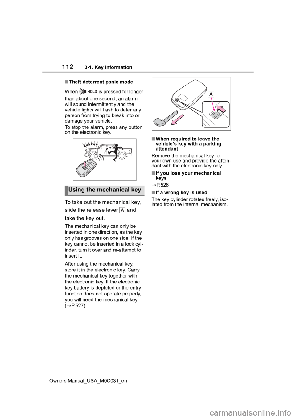
To take out the mechanical key,
slide the release lever and
take the key out.
The mechanical key can only be
inserted in one direction, as the key
only has grooves on one side. If the
key cannot be inserted in a lock cyl-
inder, turn it over and re-attempt to
insert it.
After using the mechanical key,
store it in the electronic key. Carry
the mechanical k ey together with
the electronic key. If the electronic
key battery is dep leted or the entry
function does not operate properly,
you will need the m echanical key.
( P.527)
■When required to leave the
vehicle’s key wi th a parking
attendant
Remove the mechanical key for
your own use and p rovide the atten-
dant with the elec tronic key only.
■If you lose your mechanical
keys
P.526
■If a wrong key is used
The key cylinder rotates freely, iso-
lated from the internal mechanism.Using the mechanical key
Page 119 of 618
1193-2. Opening, closing and locking the doors and tailgate
Owners Manual_USA_M0C031_en
3
Before driving
●A board is not completely stowed
●Vehicle speed is approximately 3
mph (5 km/h) or higher
The boards will not automatically
deploy again when vehicle speed
returns to less th an 3 mph (5 km/h).
■If “Running Board Unable to
Deploy” is displayed on the
multi-Information display
The board may not be completely
deployed.
Close and open the door once more
or use the switch inside the vehicle
( P.119) and completely deploy the
board.
■If “Power Steps Unable to
Retract” is displayed on the
multi-Information display
The boards may not be completely
stowed.
Check that nothing is caught
between the boards and the vehicle.
■If “Power Steps System Mal-
function See Owner’s Manual”
is displayed on the multi-infor-
mation display
The system may be malfunctioning.
Have the vehicle inspected by Toy-
ota dealer.
■When snow or mud is attached
to the boards or the boards are
frozen
The power running boards may not
operate correctly. Before stepping
on a board, check that it is com-
pletely deployed. If the power run-
ning boards are not operating
correctly, turn the power steps
switch off and refrain from use.
■After recharging/reconnecting
the 12-volt battery
If the power running boards have
not completely deployed or stowed,
the boards may not move in the
intended direction the first time they
are operated. However, from the
second time onwards, the boards
will resume nor mal operation.
■When getting in and out of the
vehicle
Take care because clothes and
shoes may become dirty due to con-
tact with the lower part of the vehicle
body.
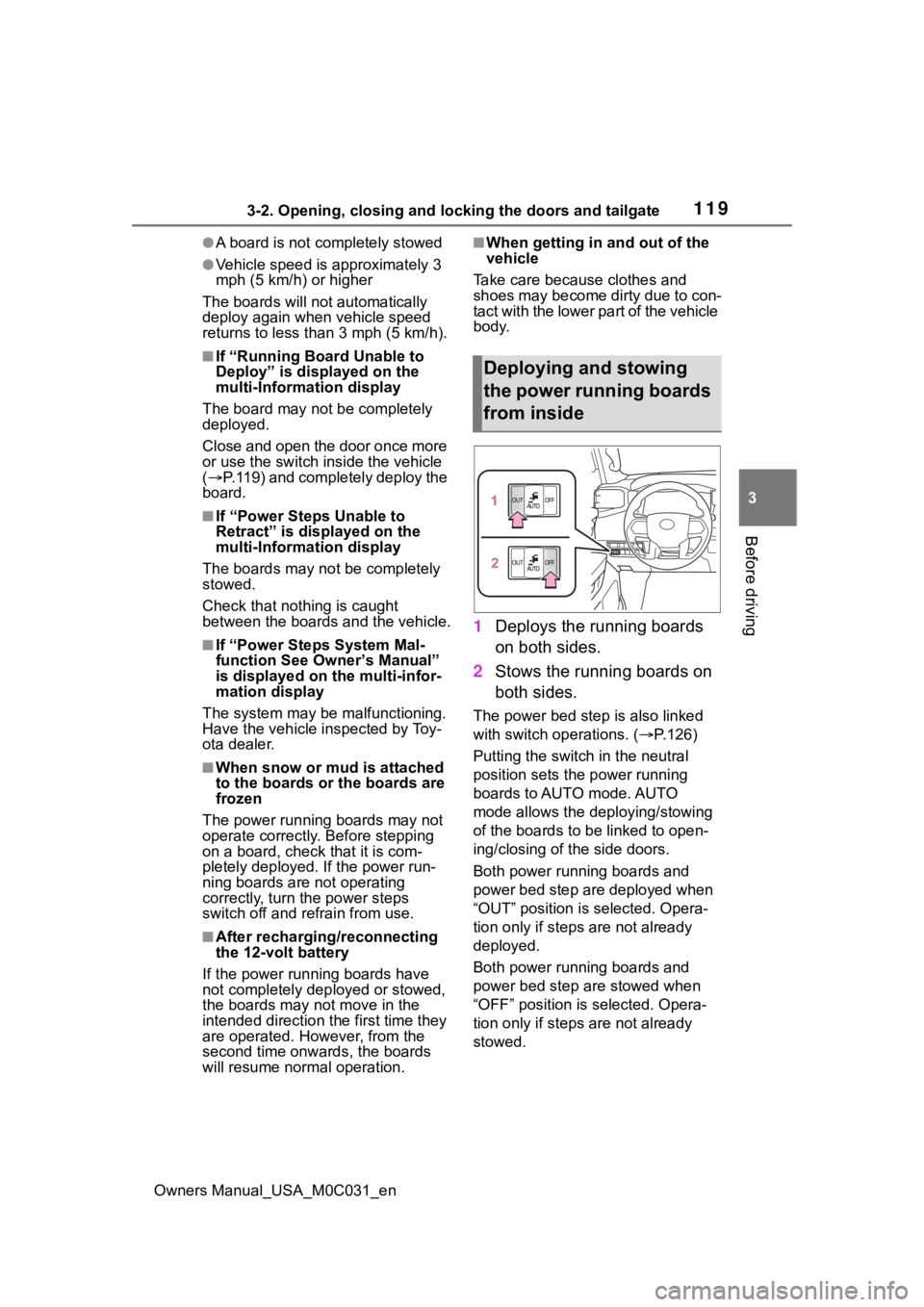
1 Deploys the running boards
on both sides.
2 Stows the running boards on
both sides.
The power bed step is also linked
with switch operations. ( P.126)
Putting the switch in the neutral
position sets the power running
boards to AUTO mode. AUTO
mode allows the deploying/stowing
of the boards to b e linked to open-
ing/closing of the side doors.
Both power running boards and
power bed step are deployed when
“OUT” position is selected. Opera-
tion only if steps are not already
deployed.
Both power running boards and
power bed step are stowed when
“OFF” position is s elected. Opera-
tion only if steps are not already
stowed.
Deploying and stowing
the power running boards
from inside
Page 128 of 618

1283-2. Opening, closing and locking the doors and tailgate
Owners Manual_USA_M0C031_en
■Antenna location
Antennas outside the cabin
Antennas inside the cabin
Antenna inside rear bumper
■Effective range (areas within
which the electronic key is
detected)
When locking or unlocking the
doors
The system can be operated when
the electronic key is within about 2.3
ft. (0.7 m) of an outside door handle.
(Only the doors de tecting the key
can be operated.)
When starting the hybrid system
or changing power switch modes
The system can be operated when
the electronic key i s inside the vehi-
cle.
When opening the tailgate
The system can be operated when
the electronic key is within about 2.3
ft. (0.7 m) of the tailgate release but-
ton.
■Alarms and warning messages
An alarm sounds and warning mes-
sages are displayed on the multi-
information disp lay to protect
against unexpect ed accidents or
theft of the vehicle resulting from
erroneous operation. When a warn-
ing message is displayed, take
appropriate measures based on the
displayed message. ( P.511)
When only an alarm sounds, cir-
cumstances and correction proce-
dures are as follows.
●When an exterior alarm sounds
once for 5 seconds
Smar t key system
The following operations
can be performed simply by
carrying the electronic key
on your person, for example
in your pocket. The driver
should always carry the
electronic key.
Locks and unlocks the
doors ( P.113)
Opens the tailgate
( P.121)
Starts the hybrid system
( P.195)