2022 TOYOTA SUPRA mirror
[x] Cancel search: mirrorPage 119 of 498
117
3
3-1. CONTROLS
CONTROLS
The head restraints are integrated
into the seatback and cannot be
adjusted.
The distance from the back of the
head is set via the backrest angle.
Adjust the distance so that the head
restraint is as close as possible to
the back of the head.
The head restraints cannot be
removed.
The mirror setting is saved for the
current driver profile. When the
vehicle is unlocked with the vehicle
key, this setting is called up auto-
matically if the f unction, see page
76, for this has been activated.
The current exterior mirror position
can be saved with the memory
function, see page 119.
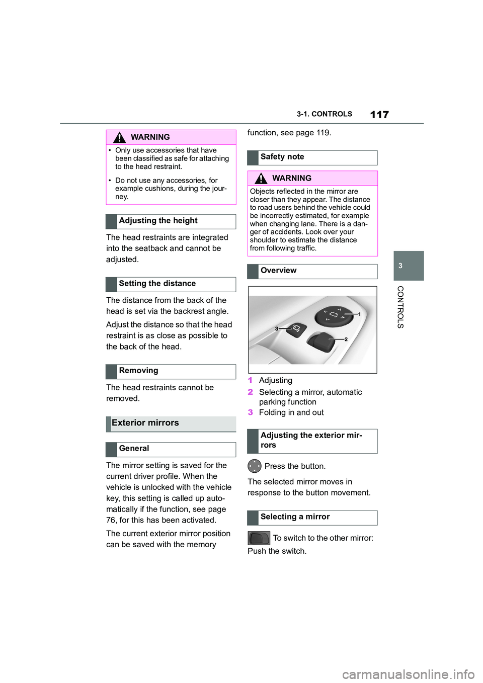
1 Adjusting
2 Selecting a mirror, automatic
parking function
3 Folding in and out
Press the button.
The selected mirror moves in
response to the button movement.
To switch to the other mirror:
Push the switch.
WA R N I N G
• Only use accessories that have
been classified as safe for attaching
to the head restraint.
• Do not use any accessories, for
example cushions, during the jour- ney.
Adjusting the height
Setting the distance
Removing
Exterior mirrors
General
Safety note
WA R N I N G
Objects reflected in the mirror are
closer than they appear. The distance to road users behind the vehicle could
be incorrectly estimated, for example
when changing lane. There is a dan-
ger of accidents. Look over your shoulder to estimate the distance
from following traffic.
Overview
Adjusting the exterior mir-
rors
Selecting a mirror
Page 120 of 498
1183-1. CONTROLS
In the event of an electrical fault,
press the edges of the mirror glass
to adjust the mirror.
Press the button.
Folding in is possible up to a speed
of approx. 20 km/h, 15 mph.
Folding the mirrors in and out is
useful in the following situations:
•In car washes.
• In narrow streets.
Folded-in mirrors automatically fold
out when the vehicle reaches a
speed of approx. 40 km/h, 25 mph.
If required, both exterior mirrors are
automatically heated when
drive-ready state is switched on.
The exterior mirror on the driver's
side is automatically dimmed. Pho-
tocells in the rear -view mirror, see
page 118, to control this function.
When reverse gear is engaged, the
mirror glass on the front passenger
side is tilted downwards. This
improves the view of the kerb or
other obstacles near the ground, for
example when parking.
1 Push the switch to the
driver's mirror position.
2 Engage selector lever position
R.
Push the switch to the front passen-
ger's mirror position.
The rear-view mirror is dimmed
automatically.
The function is controlled by photo-
cells:
• In the mirror glass.
• On the back of the mirror.
Malfunction
Folding in and out
NOTICE
Because of its width, the vehicle could
sustain damage in car washes. There is a danger of damage to property.
Before washing, fold the mirrors in
manually or with the button.
Automatic heating
Automatically dimming
Automatic parking function,
exterior mirror
Principle
Activating
Deactivating
Rear-view mirror, automatic
dim
General
Page 121 of 498
119
3
3-1. CONTROLS
CONTROLS
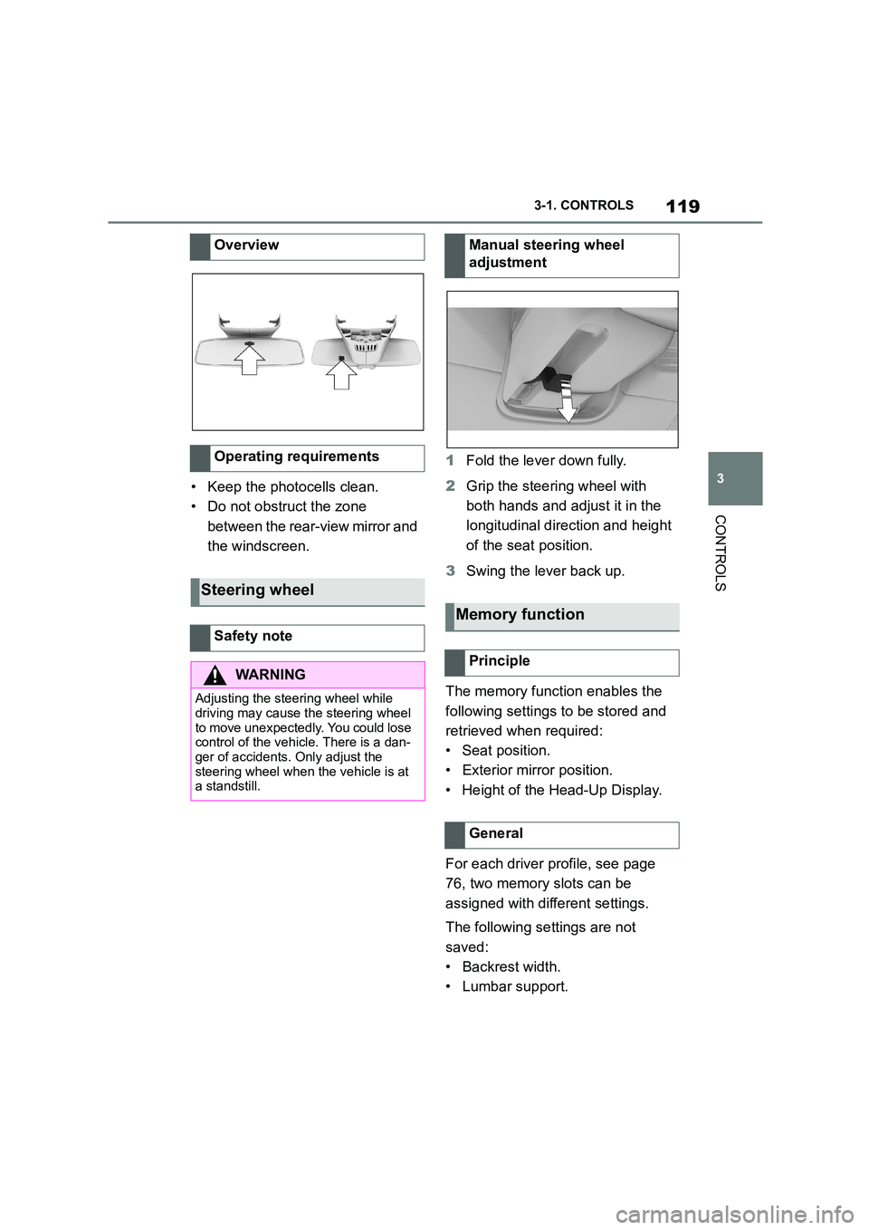
• Keep the photocells clean.
• Do not obstruct the zone
between the rear-view mirror and
the windscreen.
1 Fold the lever down fully.
2 Grip the steering wheel with
both hands and adjust it in the
longitudinal direction and height
of the seat position.
3 Swing the lever back up.
The memory function enables the
following settings to be stored and
retrieved when required:
• Seat position.
• Exterior mirror position.
• Height of the Head-Up Display.
For each driver profile, see page
76, two memory slots can be
assigned with different settings.
The following settings are not
saved:
• Backrest width.
• Lumbar support.
Overview
Operating requirements
Steering wheel
Safety note
WA R N I N G
Adjusting the steering wheel while
driving may cause the steering wheel
to move unexpectedly. You could lose control of the vehicle. There is a dan-
ger of accidents. Only adjust the
steering wheel when the vehicle is at a standstill.
Manual steering wheel
adjustment
Memory function
Principle
General
Page 152 of 498
1503-1. CONTROLS
tor lever position P engaged and
then press it.
The procedure can take a few sec-
onds. Any sounds that occur are
normal.
Do not fold in the exterior mirrors
while driving or while operating the
turn indicators or hazard warning
lights to ensure that the turn indica-
tors in the exterior mirrors are well
recognisable.
Press the lever beyond the resist-
ance point.
Briefly press the lever up or down.
The duration of the triple turn signal
can be set.
Via Toyota Supra Command:
1 "My Vehicle"
2 "Vehicle settings"
3 "Exterior lighting"
4 "One-touch turn signal"
5 Select the desired setting.
Press the lever as far as the resist-
ance point and hold it there for as
long as you wish to indicate a turn.
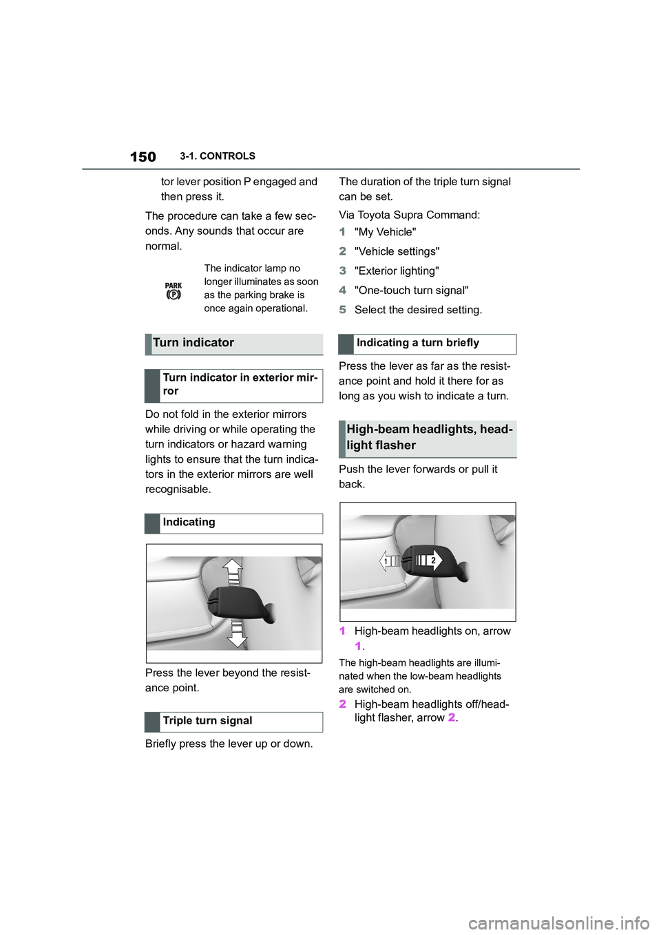
Push the lever forwards or pull it
back.
1 High-beam headlights on, arrow
1 .
The high-beam headlights are illumi-
nated when the low-beam headlights
are switched on.
2 High-beam headlights off/head-
light flasher, arrow 2.
The indicator lamp no
longer illuminates as soon
as the parking brake is
once again operational.
Turn indicator
Turn indicator in exterior mir-
ror
Indicating
Triple turn signal
Indicating a turn briefly
High-beam headlights, head-
light flasher
Page 154 of 498

1523-1. CONTROLS
Press the lever down.
To switch off: press lever down-
wards until position 0 is reached.
To flick-wipe: press the lever
downwards from position 0.
The lever returns to position 0 when
released.
The rain sensor automatically con-
trols the wiper operation depend-
ing on the rain intensity.
The sensor is mounted on the wind-
screen, directly in front of the
rear-view mirror.
Press the lever upwards from the
home position once, arrow 1.
Wiping is started.
The LED in the wiper lever is illumi-
nated.
If there is frost, a wiping process
may not be started.
Press the lever back to the home
position.
Switching off the wiper sys-
tem and flick-wiping
Rain sensor
Principle
General
Safety note
NOTICE
In car washes, the wipers may inad-
vertently start moving if the rain sen- sor is activated. There is a danger of
damage to property. Deactivate the
rain sensor in car washes.
Activating
Deactivating
Page 173 of 498
171
3
3-1. CONTROLS
CONTROLS
2 "Vehicle status"
3 "Service requirements"
4 "Date:"
5 Select the desired setting.
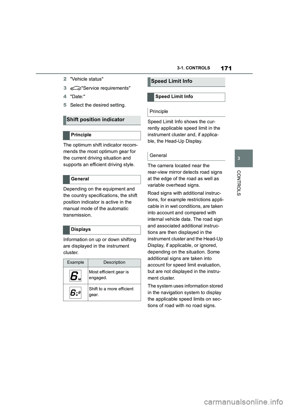
The optimum shift indicator recom-
mends the most optimum gear for
the current driving situation and
supports an efficient driving style.
Depending on the equipment and
the country specifications, the shift
position indicator is active in the
manual mode of the automatic
transmission.
Information on up or down shifting
are displayed in the instrument
cluster.
Speed Limit Info shows the cur-
rently applicable speed limit in the
instrument cluster and, if applica-
ble, the Head-Up Display.
The camera located near the
rear-view mirror detects road signs
at the edge of the road as well as
variable overhead signs.
Road signs with additional instruc-
tions, for example restrictions appli-
cable in in wet conditions, are taken
into account and compared with
internal vehicle data. The road sign
and associated additional instruc-
tions are then displayed in the
instrument cluster and the Head-Up
Display, if applic able, or ignored,
depending on the situation. Some
additional signs are taken into
account for speed limit evaluation,
but are not displayed in the instru-
ment cluster.
The system uses information stored
in the navigation system to display
the applicable speed limits on sec-
tions of road with no road signs.
Shift position indicator
Principle
General
Displays
ExampleDescription
Most efficient gear is
engaged.
Shift to a more efficient
gear.
Speed Limit Info
Speed Limit Info
Principle
General
Page 176 of 498

1743-1. CONTROLS
The camera in the area of the inte-
rior rear-view mirror detects traffic
signs at the edge of the road as
well as variable overhead signs.
Road signs with additional instruc-
tions, for example restrictions appli-
cable in wet weather, are taken into
account and correlated with infor-
mation in the vehicle, such as the
windscreen wiper signal. The road
sign and corresponding additional
signs are then displayed in the
instrument cluster and the Head-Up
Display, if applicable, or ignored,
depending on the situation. Some
additional signs are taken into
account in the evaluation of the
speed limit, but are not displayed in
the instrument cluster.
The system considers the informa-
tion saved in the navigation system
as applicable and also displays the
speed limits present on unmarked
sections of road.
Overtaking restriction signs and
end of restriction signs that are
detected by the camera are indi-
cated by corresponding symbols in
the instrument cluster and, if appli-
cable, the Head-Up Display.
The system considers overtaking
restrictions and ends of restrictions
that are indicated by means of
signs.
Nothing will be displayed in the fol-
lowing situations:
In countries where overtaking
restrictions are primarily shown
by road markings.
On routes without signs.
In the case of railway crossings,
lane markings and other situa-
tions which indicate an overtak-
ing restriction but which are not
signposted to this effect.
Depending on the equipment ver-
sion, an additional symbol with dis-
tance information may also be
displayed to indicate the end of the
overtaking restriction display.
The system is controlled using the
General
Overtaking restriction dis-
play
Principle
General
Safety note
WA R N I N G
The system does not relieve you of
your personal responsibility to assess the visibility conditions and traffic situ-
ation correctly. There is a danger of
accidents. Adapt your driving style to the traffic conditions. Observe the
traffic situation and intervene actively
if the situation warrants it.
Overview
Sensors
Page 178 of 498
1763-1. CONTROLS
Via Toyota Supra Command:
1 "My vehicle"
2 "System settings"
3 "Displays"
4 "Instrument cluster"
5 Select the desired setting:
"Warning when speeding": acti-
vate or deactivate the flashing of
the Speed Limit Info display in
the instrument cluster and the
Head-Up Display when the cur-
rently applicable speed limit is
exceeded.
"Show speeding": the speed limit
detected by the Speed Limit Info
is indicated by a mark in the
speedometer in the instrument
cluster.
The function may be restricted and
may display incorrec t information in
the following situations, for exam-
ple:
In thick fog, wet conditions or
snow.
If signs are fully or partially
obscured by objects, stickers or
paint.
If the vehicle is too close to the
vehicle ahead.
In the case of bright oncoming
light or strong reflections.
When the windscreen in front of
the rear-view mirror is covered
with condensation, dirt, stickers,
etc.
If the camera has overheated
due to excessively high tempera-
tures and has been temporarily
deactivated.
As a result of incorrect detection
by the camera.
If the speed limits stored in the
navigation system or road data
are incorrect.
In the case of speed limits that
depend or the time of day or day
of the week.
In areas not covered by the navi-
gation system.
If there are deviations in relation
to navigation, for example due to
changes in road routing.
In the case of electronic road
signs.
When overtaking buses or trucks
with road sign stickers.
If traffic signs do not correspond
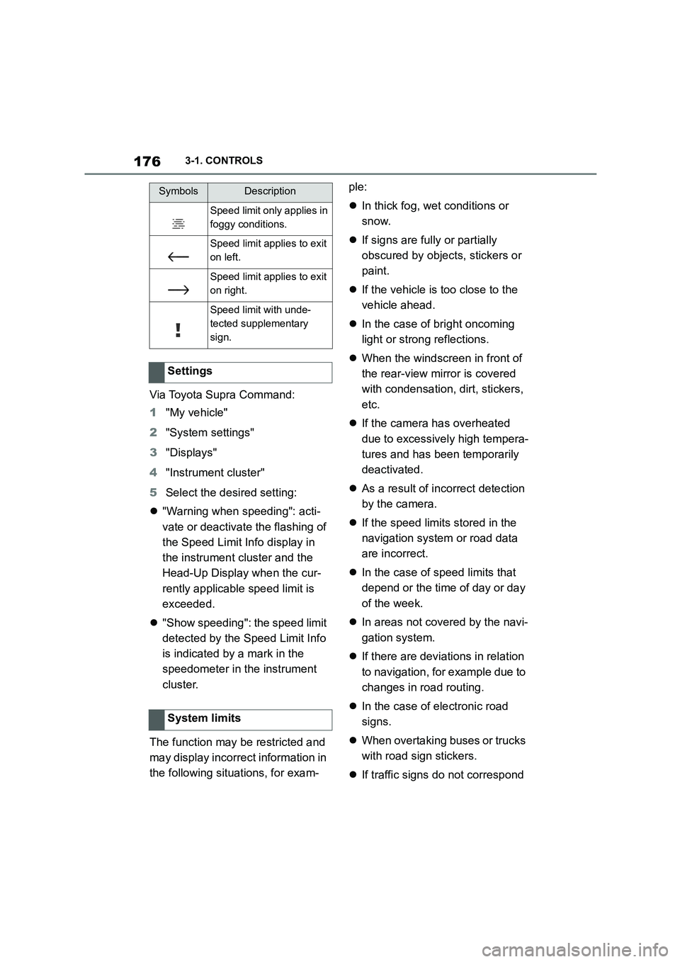
Speed limit only applies in
foggy conditions.
Speed limit applies to exit
on left.
Speed limit applies to exit
on right.
Speed limit with unde-
tected supplementary
sign.
Settings
System limits
SymbolsDescription