2022 TOYOTA SUPRA battery
[x] Cancel search: batteryPage 114 of 498
1123-1. CONTROLS
• Insert the seat belt into the belt
guide.
• Place the seat belt tightly over
the pelvis and shoulder, close to
the body and without twisting.
• Make sure that the seat belt is
positioned low at the hip in the
area of the pelvis. The seat belt
must not press on the abdomen.
• The seat belt must not be rubbed
on sharp edges, be routed over
solid or breakable objects or be
trapped.
• Avoid wearing bulky clothing.
• Keep the seat belt taut by occa-
sionally pulling upwards on the
upper section.
WA R N I N G
Care should be taken to avoid con-
tamination of the webbing by pol-
ishes, oils and chemicals and particularly battery acid. Cleaning
may safely be carried out using a mild
soap and water solution. The belt should be replaced if webbing
becomes frayed, contaminated or
damaged. Seat belts should not be
worn with straps twisted. Each seat belt assembly must only be used by
one occupant; it is forbidden to put a
belt around a child being carried on the occupant’s lap.
It is essential to replace the entire assembly after it has been worn in a
severe impact even if damage to the
assembly is not obvious.
WA R N I N G
No modifications or additions should
be made by the user that will either
prevent the seat belt adjusting
devices from operating to remove slack, or prevent the seat belt assem-
bly from being adjusted to remove
slack.
WA R N I N G
If the rear backrest is not locked, the
protective effect of the middle seat belt is not ensured. There is a danger
of injury or even death. Lock the wider
rear seat backrest when using the middle seat belt.
WA R N I N G
The protective function of the seat
belts may be limited or may even fail completely in the following situations:
• The seat belts or belt buckles are damaged, dirty or have been modi-
fied in another way.
• The seat belt tensioners or belt retractors have been modified.
Seat belts can be damaged in an accident without the damage neces-
sarily being apparent. There is a dan-
ger of injury or danger to life. Do not modify seat belts, seat belt buckles,
seat belt tensioners, belt retractors
and belt anchor points and ensure that they are kept clean. After an acci-
dent, have the seat belts inspected at
any authorized Toyota retailer or Toyota authorized repairer, or any reli-
able repairer.
Correct seat belt use
Page 148 of 498
1463-1. CONTROLS
On steep downward gradients.
Brake not pressed strongly
enough.
High outside temperature and
operation of the automatic air
conditioning.
Interior not heated or cooled to
the desired temperature.
Where there is a risk of conden-
sation when the automatic air
conditioning is switched on.
Engine or other parts not at oper-
ating temperature.
Engine cooling is required.
Sharp steering angle or steering
operation.
Vehicle battery is heavily dis-
charged.
At high altitudes.
Bonnet is unlocked.
Park Assistant is activated.
Stop-and-go traffic.
Selector lever position in N or R.
After reversing.
Use of fuel with high ethanol
content.
For driving off, the engine automati-
cally starts under the following con-
ditions:
By releasing the brake pedal.
After starting the engine, accelerate
as normal.
After an automatic shut down, the
engine will not rest art automatically,
if one of the following conditions is
met:
Driver's seat belt unbuckled and
driver's door open.
Bonnet has been unlocked.
Several indicator lamps illuminate
for various lengths of time.
The engine can only be started
using the start/stop button.
Even if you do not want to drive off,
the engine restarts automatically in
the following situations:
Very high temperature in the
interior when the cooling function
is switched on.
Very low temperature in the inte-
rior when the heating is switched
on.
Where there is a risk of conden-
sation when the automatic air
conditioning is switched on.
When the steering wheel is
turned.
Shift from selector lever position
D to N or R.
Engine start
Operating requirements
Driving off
Safety function
System limits
Page 149 of 498

147
3
3-1. CONTROLS
CONTROLS
Shift from selector lever position
P to N, D or R.
Vehicle battery is heavily dis-
charged.
Start of an oil level measure-
ment.
Depending on the equipment ver-
sion and country version, the vehi-
cle has various sensors to record
the traffic situation. This enables
the intelligent auto matic Start/Stop
function to adapt to various traffic
situations and, where necessary,
behave in an anticipatory manner.
For example, in the following situa-
tions:
If a situation is detected in which
the duration of the stop is likely
to be very short, the engine is not
stopped automatically. Depend-
ing on the situation, a message
is shown on the Control Display.
If a situation is detected in which
the vehicle should drive off
immediately, the stopped engine
is started automatically.
The function may be limited if the
navigation data is invalid, outdated
or not available, for example.
The engine is not switched off auto-
matically.
During an automatic engine stop,
the engine is started.
Press the button.
The Auto Start/Stop is also deacti-
vated in selector lever position M.
The Auto Start/Stop is also deacti-
vated in the SPORT drive mode of
the Sport mode switch.
■General
With automatic engine stop, the
vehicle can be parked safely, for
Auto Start/Stop additional
function
Manually deactivating/acti-
vating the system
Principle
Using the button
Via selector lever position
Sport mode switch
Parking the vehicle during auto-
matic engine stop
Page 188 of 498
1863-1. CONTROLS
drive-ready state is switched off,
the exterior lights are switched off
automatically after a given time.
The side lights can only be
switched on in the low speed range.
The vehicle is illuminated all round.
Do not leave the side lights on for
extended periods of time, since the
vehicle battery could discharge and
it may no longer be possible to
switch on drive-ready state.
After switching on the drive-ready
state, the automat ic driving lights
control is activated.
The low-beam head lights illuminate
if drive-ready state is switched on.
To switch on the low-beam head-
lights as soon as the standby state
is switched on, press the button
again.
Depending on the country specifi-
cations, the low-beam headlights
may be switched off in the low
speed range.
Depending on the surrounding con-
ditions, the low beam headlights
may not be able to be turned off.
When parking the vehicle, it is pos-
sible to switch on a parking light on
one side.
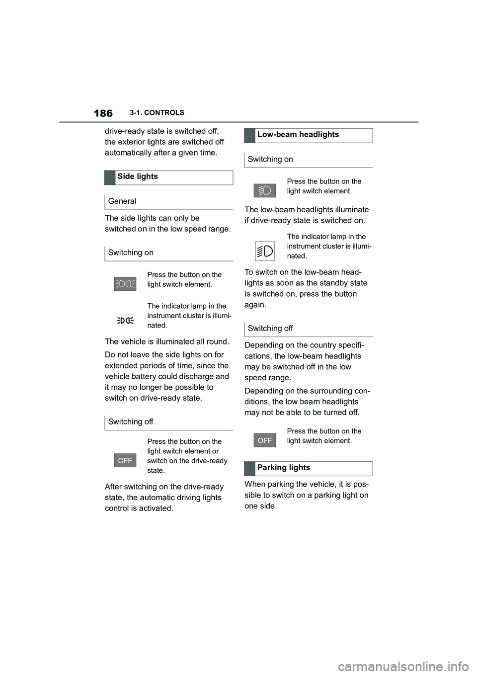
Side lights
General
Switching on
Press the button on the
light switch element.
The indicator lamp in the
instrument cluster is illumi-
nated.
Switching off
Press the button on the
light switch element or
switch on the drive-ready
state.
Low-beam headlights
Switching on
Press the button on the
light switch element.
The indicator lamp in the
instrument cluster is illumi-
nated.
Switching off
Press the button on the
light switch element.
Parking lights
Page 267 of 498
265
3
3-1. CONTROLS
CONTROLS
In order to protect the battery the
air flow rate of the automatic air
conditioning is reduced, if neces-
sary.
The air distribution for air condition-
ing can be set manually.
Windows, upper body area and
footwell.
Upper body area and footwell.
Footwell.
Windows and footwell.
Windows.
Windows and upper body.
Upper body area.
The selected air distribution is
shown on the display for automatic
air conditioning.
If there is condensation, remove it,
see page 265.
Ice and condensation are quickly
removed from the windscreen and
the front side windows.
The LED is illuminated when the
system is switched on.
The air flow can be adjusted manu-
ally when the system is switched
on.
The function is available when the
engine is running.
The rear window heating is
switched off automatically after a
certain period of time.
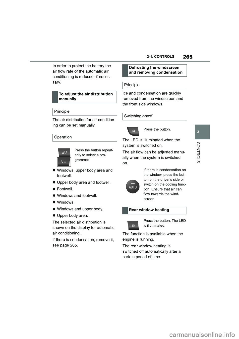
To adjust the air distribution
manually
Principle
Operation
Press the button repeat-
edly to select a pro-
gramme:
Defrosting the windscreen
and removing condensation
Principle
Switching on/off
Press the button.
If there is condensation on
the window, press the but-
ton on the driver's side or
switch on the cooling func-
tion. Ensure that air can
flow towards the wind-
screen.
Rear window heating
Press the button. The LED
is illuminated.
Page 269 of 498

267
3
3-1. CONTROLS
CONTROLS
The independent ventilation allows
the temperature of the interior to be
adjusted before the journey starts.
Depending on the set temperature
and ambient temperature, the inte-
rior is ventilated or heated using
any available residual heat from the
engine.
The system can be switched on
and off directly or for a preselected
departure time.
The switch-on time is calculated
based on the outside temperature.
The system will switch on in good
time before the preselected depar-
ture time.
Vehicle is in rest or standby state
and not in drive-ready state.
Battery is sufficiently charged.
When activated, the independent venti-
lation uses power from the vehicle bat-
tery. As a result, the maximum
activation time is restricted to protect
the battery. After the engine is started
or after driving a short distance, the
system will be av ailable again.
Ensure that the date and time
are set correctly in the vehicle.
Open the vents to allow the air to
enter the passenger compart-
ment.
The system can be switched on or
off in various ways.
The system switches off automati-
cally after a certain period of time. It
continues to run for a short time
after it has been switched off.
■General
If the vehicle is in standby state, the
independent ventilation can be
switched on or off via the buttons of
the automatic air conditioning.
■Switching on
Press any button, except:
Rear window heating.
Lower side of air flow button.
Seat heating.
■Switching off
The system switches off after leav-
ing and locking the vehicle.
Press and hold the down
button.
1 "My Vehicle"
2 "Vehicle settings"
Independent ventilation
Principle
General
Operating requirements
Switching on/off directly
General
Using the button
Via Toyota Supra Command
Page 272 of 498
2703-1. CONTROLS
cal devices when standby state or
drive-ready state is switched on.
The total load of all sockets must
not exceed 140 watts at 12 volts.
To avoid damage to the socket, do
not insert an incompatible plug.
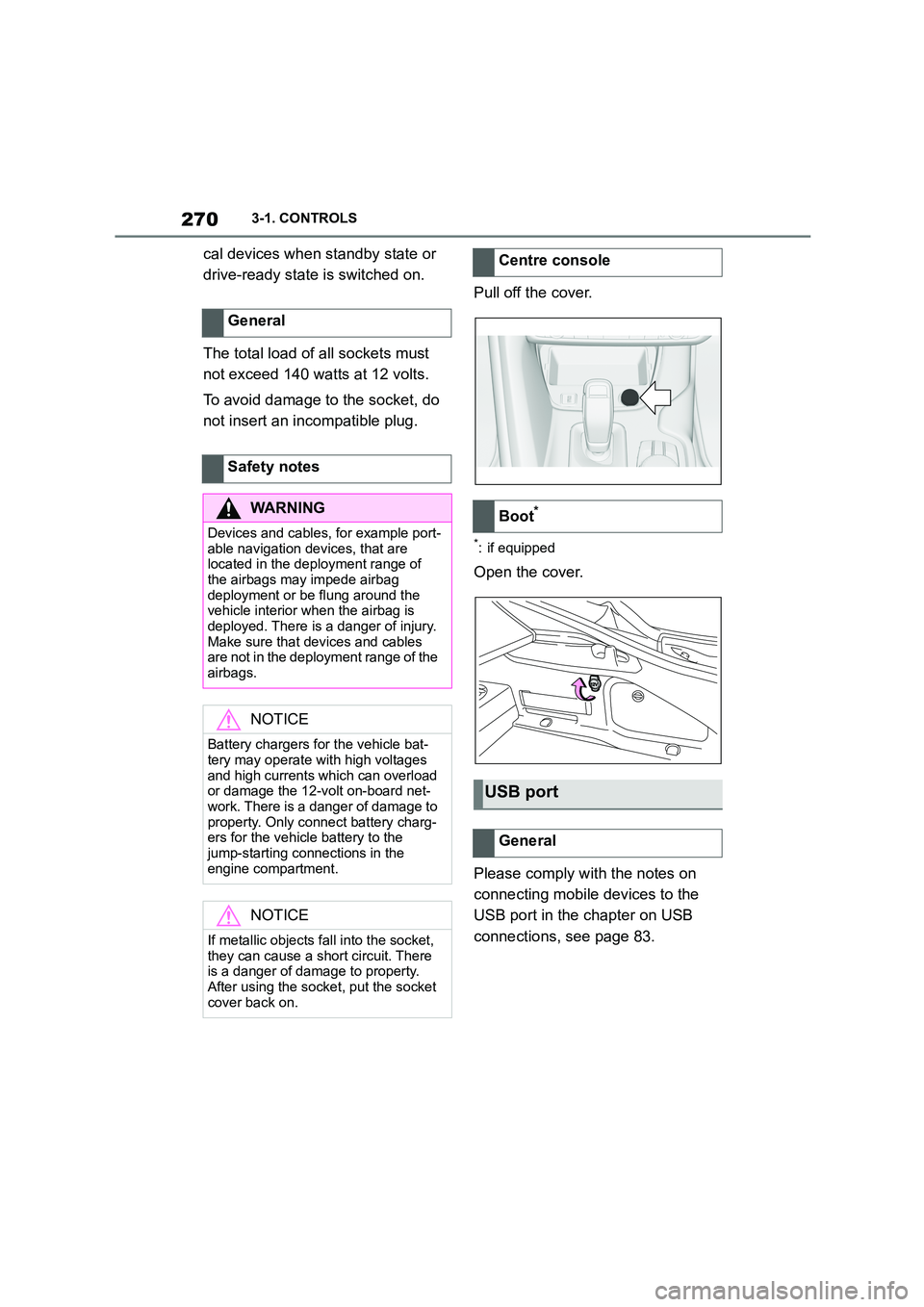
Pull off the cover.
*: if equipped
Open the cover.
Please comply with the notes on
connecting mobile devices to the
USB port in the chapter on USB
connections, see page 83.
General
Safety notes
WA R N I N G
Devices and cables, for example port-
able navigation devices, that are located in the deployment range of
the airbags may impede airbag
deployment or be flung around the vehicle interior when the airbag is
deployed. There is a danger of injury.
Make sure that devices and cables are not in the deployment range of the
airbags.
NOTICE
Battery chargers for the vehicle bat- tery may operate with high voltages
and high currents which can overload
or damage the 12-volt on-board net- work. There is a danger of damage to
property. Only connect battery charg-
ers for the vehicle battery to the jump-starting connections in the
engine compartment.
NOTICE
If metallic objects fall into the socket,
they can cause a short circuit. There
is a danger of damage to property.
After using the socket, put the socket cover back on.
Centre console
Boot*
USB port
General
Page 322 of 498
3205-1. MOBILITY
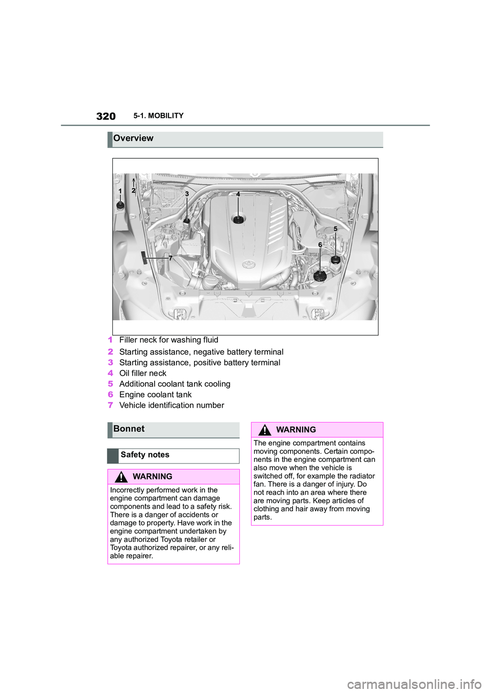
1Filler neck for washing fluid
2 Starting assistance, negative battery terminal
3 Starting assistance, positive battery terminal
4 Oil filler neck
5 Additional coolant tank cooling
6 Engine coolant tank
7 Vehicle identification number
Overview
Bonnet
Safety notes
WA R N I N G
Incorrectly performed work in the
engine compartment can damage components and lead to a safety risk.
There is a danger of accidents or
damage to property. Have work in the engine compartment undertaken by
any authorized Toyota retailer or
Toyota authorized repairer, or any reli- able repairer.
WA R N I N G
The engine compartment contains
moving components. Certain compo- nents in the engine compartment can
also move when the vehicle is
switched off, for example the radiator fan. There is a danger of injury. Do
not reach into an area where there
are moving parts. Keep articles of clothing and hair away from moving
parts.