Page 476 of 568
4767-2. Steps to take in an emergency
holding bracket from the
hoist assembly .
9 Tilt the holding bracket so
that it can easily be passed
through the wheel opening.
After passing the holding
bracket through the wheel
opening, remove the hoist
assembly . 1
Chock the tires.
2 Slightly loosen the wheel
nuts (one turn).
Vehicles with wheel locks: Use the
wheel lock key to loosen the wheel
WARNING
■When storing the spare tire
Be careful not to catch fingers or
other body parts between the
spare tire and the body of the
vehicle.
Replacing a flat tire
Flat tireWheel chock
positions
Front left-hand
sideBehind the rear
right-hand side
tire
Front right-hand
sideBehind the rear
left-hand side tire
Rear left-hand
sideIn front of the
front right-hand
side tire
Rear right-hand
sideIn front of the
front left-hand
side tire
Page 478 of 568

4787-2. Steps to take in an emergency
ered, the wire cable may be sev-
ered. Have the vehicle inspected by
your Toyota dealer.
1Remove any dirt or foreign
matter from the wheel con-
tact surface.
If foreign matter is on the wheel
contact surface, the wheel nuts
may loosen while the vehicle is in
WARNING
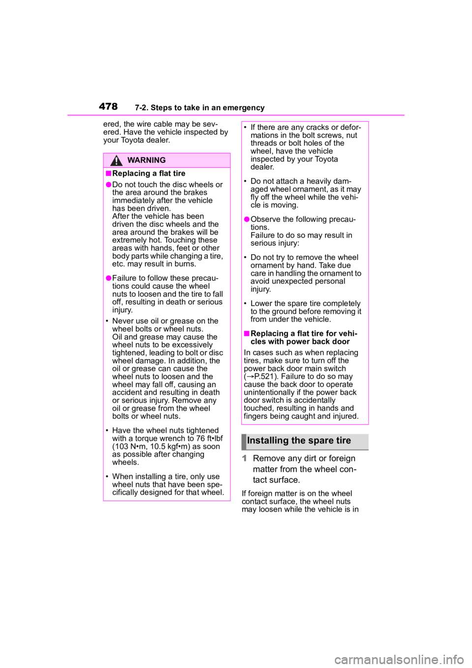
■Replacing a flat tire
●Do not touch the disc wheels or
the area around the brakes
immediately after the vehicle
has been driven.
After the vehicle has been
driven the disc wheels and the
area around the brakes will be
extremely hot. Touching these
areas with hands , feet or other
body parts while changing a tire,
etc. may result in burns.
●Failure to follow these precau-
tions could cause the wheel
nuts to loosen and the tire to fall
off, resulting in death or serious
injury.
• Never use oil or grease on the wheel bolts or wheel nuts.
Oil and grease may cause the
wheel nuts to be excessively
tightened, leading to bolt or disc
wheel damage. In addition, the
oil or grease can cause the
wheel nuts to loosen and the
wheel may fall off, causing an
accident and resulting in death
or serious injury. Remove any
oil or grease from the wheel
bolts or wheel nuts.
• Have the wheel nuts tightened with a torque wrench to 76 ft•lbf
(103 N•m, 10.5 kgf•m) as soon
as possible after changing
wheels.
• When installing a tire, only use wheel nuts that have been spe-
cifically designed for that wheel.
• If there are any cracks or defor- mations in the bolt screws, nut
threads or bolt holes of the
wheel, have the vehicle
inspected by your Toyota
dealer.
• Do not attach a heavily dam- aged wheel ornament, as it may
fly off the wheel while the vehi-
cle is moving.
●Observe the fo llowing precau-
tions.
Failure to do so may result in
serious injury:
• Do not try to remove the wheel ornament by hand. Take due
care in handling the ornament to
avoid unexpected personal
injury.
• Lower the spare tire completely to the ground before removing it
from under the vehicle.
■Replacing a flat tire for vehi-
cles with power back door
In cases such as when replacing
tires, make sure to turn off the
power back door main switch
( P.521). Failure to do so may
cause the back d oor to operate
unintentionally if the power back
door switch is accidentally
touched, resulti ng in hands and
fingers being caught and injured.
Installing the spare tire
Page 479 of 568
4797-2. Steps to take in an emergency
7
When trouble arises
motion, causing the tire to come off.
2Install the spare tire and
loosely tighten each wheel
nut by hand by approximately
the same amount.
When replacing an aluminum wheel
with an aluminum wheel, turn the
wheel nuts until the washers
come into contact with the disc
wheel .
When replacing an aluminum wheel
with a steel wheel, tighten the
wheel nuts until the tapered portion
comes into loose contact with
the disc wheel seat .
3 Lower the vehicle.
4 Firmly tighten each wheel nut
two or three times in the
order shown in the illustra-
tion.
Vehicles with wheel locks: Tighten
the wheel lock using the wheel lock
key after tightening the other wheel
nuts.
Tightening torque:
76 ft•lbf (103 N•m, 10.5 kgf•m)
WARNING
■Stowing the flat tire
Failure to follow steps listed under
stowing the tire may result in
damage to the spare tire carrier
and loss of the tire, which could
result in serious injury or death.
Page 480 of 568
4807-2. Steps to take in an emergency
1Remove the center wheel
ornament by pushing from
the reverse side.
Be careful not to lose the wheel
ornament.
2Stand the tire against the
bumper with the inner sur-
face facing toward you. Pass
the hoist assembly and
holding bracket through
the wheel opening.
3 Fully depress the secondary
latch and install the bracket to the hoist
assembly .
4 Lay the tire on the ground
with the outer surface (valve
stem) facing up.
5 Before raising the tire, make
sure that the hoist assembly
is perpendicular to the wheel
opening. (Try to place the tire
directly beneath the vehicle,
Stowing the flat tire, jack
and all tools
Page 481 of 568

4817-2. Steps to take in an emergency
7
When trouble arises
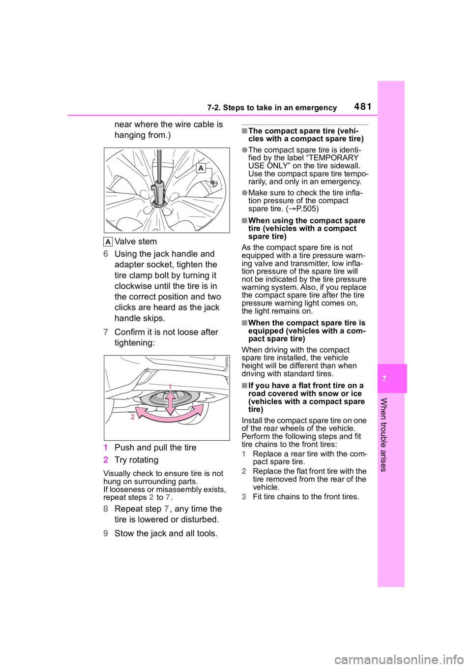
near where the wire cable is
hanging from.)
Valve stem
6 Using the jack handle and
adapter socket, tighten the
tire clamp bolt by turning it
clockwise until the tire is in
the correct position and two
clicks are heard as the jack
handle skips.
7 Confirm it is not loose after
tightening:
1 Push and pull the tire
2 Try rotating
Visually check to ensure tire is not
hung on surrounding parts.
If looseness or misassembly exists,
repeat steps 2 to 7.
8 Repeat step 7, any time the
tire is lowered or disturbed.
9 Stow the jack and all tools.
■The compact spare tire (vehi-
cles with a compact spare tire)
●The compact spare tire is identi-
fied by the label “TEMPORARY
USE ONLY” on the tire sidewall.
Use the compact spare tire tempo-
rarily, and only in an emergency.
●Make sure to check the tire infla-
tion pressure of the compact
spare tire. ( P.505)
■When using the compact spare
tire (vehicles with a compact
spare tire)
As the compact spare tire is not
equipped with a tire pressure warn-
ing valve and transm itter, low infla-
tion pressure of t he spare tire will
not be indicated by the tire pressure
warning system. Also , if you replace
the compact spare ti re after the tire
pressure warning light comes on,
the light remains on.
■When the compact spare tire is
equipped (vehicles with a com-
pact spare tire)
When driving with the compact
spare tire installed, the vehicle
height will be diffe rent than when
driving with standard tires.
■If you have a flat front tire on a
road covered wit h snow or ice
(vehicles with a compact spare
tire)
Install the compact spare tire on one
of the rear wheels of the vehicle.
Perform the following steps and fit
tire chains to the front tires:
1 Replace a rear tire with the com-
pact spare tire.
2 Replace the flat front tire with the
tire removed from the rear of the
vehicle.
3 Fit tire chains to the front tires.
Page 483 of 568

4837-2. Steps to take in an emergency
7
When trouble arises
NOTICE
■Be careful when driving over
bumps with the compact
spare tire installed on the
vehicle (vehicles with a com-
pact spare tire)
The vehicle becomes lower when
driving with the compact spare tire
compared to when driving with
standard tires. Be careful when
driving over uneven road sur-
faces.
■Driving with tire chains and
the compact spare tire (vehi-
cles with a compact spare
tire)
Do not fit tire chains to the com-
pact spare tire. Tire chains may
damage the vehicle body and
adversely affect driving perfor-
mance.
■When replacing the tires
When removing or fitting the
wheels, tires or the tire pressure
warning valve and transmitter,
contact your Toyota dealer as the
tire pressure warning valve and
transmitter may be damaged if not
handled correctly.
■When stowing the flat tire
●Ensure that there is no object
caught between the tire and the
vehicle underbody.
●Securely tighten the spare tire
clamp bolt to hold the spare
wheel carrier by the hook.
●Stow the flat tire in the spare tire
location. Failure to do so may
cause damage to the spare tire
carrier. Proper storage reduces
the possibility of injury in a colli-
sion or during sudden braking.
●Have the flat tire repaired and
the spare tire replaced with it as
soon as possible.
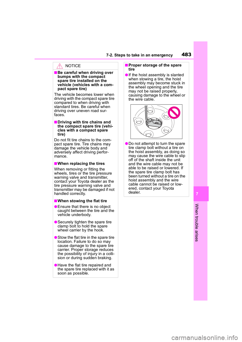
■Proper storage of the spare
tire
●If the hoist assembly is slanted
when stowing a tire, the hoist
assembly may become stuck in
the wheel opening and the tire
may not be raised properly,
causing damage to the wheel or
the wire cable.
●Do not attempt to turn the spare
tire clamp bolt without a tire on
the hoist assembly, as doing so
may cause the wire cable to slip
off of the shaft inside the unit
and the wire cable may not be
able to be raised or lowered. If
the spare tire clamp bolt has
been turned without a tire on the
hoist assembly and the wire
cable cannot be raised or low-
ered, contact your Toyota
dealer.
Page 505 of 568
5058-1. Specifications
8
Vehicle specifications
*: Minimum pedal clearance when depressed with a force of 67.4 lbf (300 N, 30.6 kgf) while the engine is running.
Ty p e A
Steering
Free playLess than 1.2 in. (30 mm)
Tires and wheels
Tire size235/65R18 106V, T165/90D18 107M (spare)
Tire inflation pressure
(Recommended cold tire
inflation pressure)
Front
36 psi (250 kPa, 2.5 kgf/cm
2 or bar)
Rear
36 psi (250 kPa, 2.5 kgf/cm
2 or bar)
Spare
60 psi (420 kPa, 4.2 kgf/cm
2 or bar)
Driving at high speeds (above 100 mph [160
km/h]) (in countries wher e such speeds are per-
mitted by law)
Add 4 psi (30 kPa, 0.3 kgf/cm
2 or bar) to the front
and rear tires. Never exceed the maximum cold
tire inflation pressure in dicated on the tire side-
wall.
Wheel size18 8 J, 18 4T (spare)
Wheel nut torque76 ft•lbf (103 N•m, 10.5 kgf•m)
Page 506 of 568

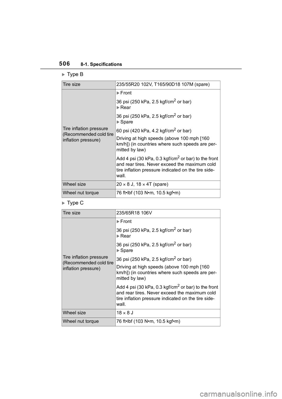
5068-1. Specifications
Ty p e B
Ty p e C
Tire size235/55R20 102V, T165/90D18 107M (spare)
Tire inflation pressure
(Recommended cold tire
inflation pressure)
Front
36 psi (250 kPa, 2.5 kgf/cm
2 or bar)
Rear
36 psi (250 kPa, 2.5 kgf/cm
2 or bar)
Spare
60 psi (420 kPa, 4.2 kgf/cm
2 or bar)
Driving at high speeds (above 100 mph [160
km/h]) (in countries wher e such speeds are per-
mitted by law)
Add 4 psi (30 kPa, 0.3 kgf/cm
2 or bar) to the front
and rear tires. Never exceed the maximum cold
tire inflation pressure in dicated on the tire side-
wall.
Wheel size20 8 J, 18 4T (spare)
Wheel nut torque76 ft•lbf (103 N•m, 10.5 kgf•m)
Tire size235/65R18 106V
Tire inflation pressure
(Recommended cold tire
inflation pressure)
Front
36 psi (250 kPa, 2.5 kgf/cm
2 or bar)
Rear
36 psi (250 kPa, 2.5 kgf/cm
2 or bar)
Spare
36 psi (250 kPa, 2.5 kgf/cm
2 or bar)
Driving at high speeds (above 100 mph [160
km/h]) (in countries wher e such speeds are per-
mitted by law)
Add 4 psi (30 kPa, 0.3 kgf/cm
2 or bar) to the front
and rear tires. Never exceed the maximum cold
tire inflation pressure in dicated on the tire side-
wall.
Wheel size18 8 J
Wheel nut torque76 ft•lbf (103 N•m, 10.5 kgf•m)