2022 TOYOTA GR SUPRA lights
[x] Cancel search: lightsPage 198 of 356

1983-1. CONTROLS
If Traction mode is activated,
TRACTION is displayed in the
instrument cluster.
In certain situations, the VSC is
activated automatically:
If Dynamic radar cruise con-
trol with full-speed range is
activated.
On a braking intervention by
the Toyota Supra Safety sys-
tems.
The vehicle has a flat tire.
*: if equipped
The active differential step-
lessly locks the rear axle
depending on the driving condi-
tions. This provides optimal
power transfer in all driving con-
ditions by helping prevent wheel
spin at either rear wheel.
The driver is responsible adapt-
ing his or her driving style to the
situation.
Activating/deactivating
Traction mode
Activating Traction mode
Press the button.
TRACTION is displayed in
the instrument cluster and
the indicator light for VSC
OFF lights up.
Deactivating Traction mode
Press the button again.
TRACTION and the VSC
OFF indicator light go out.
Display
Display in the instrument
cluster
Indicator/warning lights
The indicator light lights
up: Traction mode is acti-
vated.
Automatic program
change
Active differential*
Page 209 of 356

2093-1. CONTROLS
3
CONTROLS
Some system information can
also be displayed in the
Head-up Display.The distance information is
active in the following situations:
Dynamic radar cruise control
switched off.
Display in the Head-up Dis-
play selected, refer to page
150.
Distance too short.
Speed greater than approx.
40 mph/70 km/h.
Additional information:
• Cameras, refer to page 40.
• Radar sensors, refer to page 41.
Indicator/warning lights
SymbolDescription
Indicator light green:
system is active.
No indicator light:
system is switched
off.
Vehicle symbol
flashes:
The conditions are
not adequate for the
system to work.
The system was
deactivated but
applies the brakes
until you actively
resume control by
pressing on the
brake pedal or accel-
erator pedal.
The vehicle symbol
and distance bars
flash red and an
acoustic signal
sounds:
Brake and make an
evasive maneuver, if
necessary.
Displays in the Head-up
Display
Desired speed
The symbol is displayed
when the set desired
speed is reached.
Distance information
The symbol is displayed
when the distance from
the vehicle traveling
ahead is too short.
System limits
System limits of the sensors
Page 210 of 356

2103-1. CONTROLS
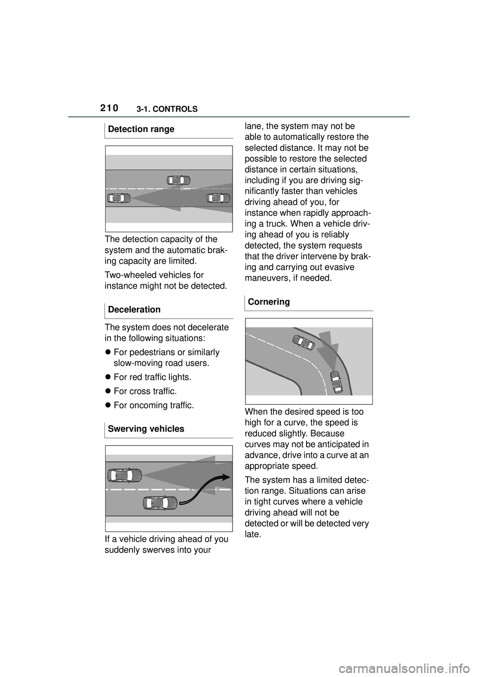
The detection capacity of the
system and the automatic brak-
ing capacity are limited.
Two-wheeled vehicles for
instance might not be detected.
The system does not decelerate
in the following situations:
For pedestrians or similarly
slow-moving road users.
For red traffic lights.
For cross traffic.
For oncoming traffic.
If a vehicle driving ahead of you
suddenly swerves into your lane, the system may not be
able to automatically restore the
selected distance. It may not be
possible to restore the selected
distance in certain situations,
including if you are driving sig-
nificantly faster than vehicles
driving ahead of you, for
instance when rapidly approach-
ing a truck. When a vehicle driv-
ing ahead of you is reliably
detected, the system requests
that the driver intervene by brak-
ing and carrying out evasive
maneuvers, if needed.
When the desired speed is too
high for a curve, the speed is
reduced slightly. Because
curves may not be anticipated in
advance, drive into a curve at an
appropriate speed.
The system has a limited detec-
tion range. Situations can arise
in tight curves where a vehicle
driving ahead will not be
detected or will be detected very
late.
Detection range
Deceleration
Swerving vehicles
Cornering
Page 213 of 356

2133-1. CONTROLS
3
CONTROLS
Speed Limit Assist is based on
the Speed Limit Info system.
Thus, also observe the system
limits of the Speed Limit Info
system, refer to page 143.
Parking Sensor is a support
when parking. Objects that you
are approaching slowly in front
of or behind the vehicle are indi-
cated by signal tones and a dis-
play on the Control Display.
Depending on the equipment version: Obstacles at the side of
the vehicle that are detected by
the side ultrasonic sensors may
also be reported by the side pro-
tection, refer to page 217, func-
tion.
The ultrasound sensors for dis-
tance measurements are
located in the bumpers and pos-
sibly on the sides of the vehicle.
The range, depending on the
obstacle and environmental
conditions, is approx. 6 ft/2 m.
An acoustic warning sounds in
case of an impending collision at
a distance to the object of
approx. 27 in/70 cm.
For objects behind the vehicle,
the acoustic warning is already
issued at a distance to the
object of approx. 5 ft/1.50 m.
Detected change of a
speed limit with imme-
diate effect.
Indicator light illumi-
nates green: the
detected speed limit
can be applied with the
SET button.
As soon as the speed
limit has been applied,
a green checkmark is
displayed.
Taking over the sug-
gested speed
As soon as the SET icon
lights up, press the button.
System limits
Parking Sensors
Concept
SymbolFunction
General information
Safety information
WARNING
The system cannot serve as a
substitute for the driver’s personal
judgment in assessing the traffic
conditions. Based on the limits of
the system, it cannot inde-
pendently react to all traffic situa-
tions. There is a risk of accident.
Adjust driving style to traffic condi-
tions. Watch traffic closely and
actively intervene where appropri-
ate.
Page 215 of 356

2153-1. CONTROLS
3
CONTROLS
On: the LED lights up.
Off: the LED goes out.
The rearview camera image is
displayed if the reverse gear is
engaged when pressing the
park assistance button.
Depending on the equipment
version, the system cannot be
switched off manually if the
reverse gear is engaged.
■General information
An intermittent tone indicates
when the vehicle is approaching
an object. For instance, if an
object is detected to the left rear
of the vehicle, a signal tone
sounds from the left rear
speaker.
The shorter the distance to the
object, the shorter the intervals.
If the distance to a detected
object is less than approx. 8
in/20 cm, a continuous tone is
sounded.
If there are objects in front of
and behind the vehicle at the
same time, with a distance
smaller than approx. 8 in/20 cm,
an alternating constant tone will sound.
The intermittent tone and con-
stant tone are switched off if the
selector lever position P is
engaged.
The intermittent tone is switched
off after a short time when the
vehicle is stationary.
■Vo l u m e
The Parking Sensor signal tone
volume can be adjusted.
Via Toyota Supra Command:
1 "My vehicle"
2 "System settings"
3 "Tone"
4 "Volume settings"
5 "Parking Sens."
6 Set the desired value.
The approach of the vehicle to
an object is shown on the Con-
trol Display. Objects that are far-
ther away are already displayed
on the Control Display before a
signal sounds.
The display appears as soon as
Switching on/off manually
Press the park assistance
button.
WARNING
Signal tones
Visual warning
Page 219 of 356

2193-1. CONTROLS
3
CONTROLS
The system is controlled by the
following sensors:
• Rearview camera.
Additional information:
Sensors of the vehicle, refer to
page 40.
The system is switched on auto-
matically if selector lever posi-
tion R is engaged when the
engine is running.
The system switches off when a
certain driving distance or speed is exceeded.
Switch the system back on, if
needed.
On: the LED lights up.
Off: the LED goes out.
The parking assistance func-
tions are shown on the Control
Display.
If the rearview camera view is
not displayed, change the view
via Toyota Supra Command:
1 If necessary, tilt the controller
to the side.
2 "Rear view camera"
The rearview camera image is
displayed.
The rearview camera is
switched on.
Keep the recording range of
the camera clear. Protruding
cargo or roof rack systems
can limit the detection range
of the camera.
Overview
Depending on the vehicle
equipment: button in the
vehicle
Park assistance button
Sensors
Switching on/off
Switching on automatically
Automatic deactivation
during forward travel
Depending on the vehicle
equipment: switching on/off
manually
Press the park assistance
button.
Switching the view via Toy-
ota Supra Command
Functional requirements
Page 231 of 356

2313-1. CONTROLS
3
CONTROLS
quickly removed from the wind-
shield and the front side win-
dows.
The LED is illuminated with the
system switched on.
The air flow can be adjusted
manually with the system
switched on.
The function is available with the
engine running.
The rear window defroster
switches off automatically after a
certain period of time.
The microfilter removes dust
and pollen from the incoming air.
Have this filter changed during
vehicle maintenance, refer to
page 301.The air flow directions can be
individually adjusted.
The air flow directions can be
adjusted for direct or indirect
ventilation.
Open the vents and position
them to ensure effective climate
control.
The air flow is directed towards
the passengers. The air flow
heats or cools noticeably,
depending on the adjusted tem-
perature.
The air flow is not directed
towards the passengers. The
car's interior is warmed or
cooled indirectly, depending on
the set temperature.
Switching on/off
Press the button.
If there is any window
condensation, press the
button on the driver's
side or switch on the air
conditioning. Make sure
that air can flow to the
windshield.
Rear window defroster
Press the button. The
LED lights up.
Microfilter
Ventilation
Concept
Adjusting the ventilation
General information
Direct ventilation
Indirect ventilation
Page 236 of 356

2363-1. CONTROLS
interior mirror simultaneously
for approximately 10 seconds
until the LED flashes green
rapidly. This erases all pro-
gramming of the buttons on
the interior mirror.
3 Press the interior mirror but-
ton to be programmed. The
LED on the interior mirror will
slowly begin flashing orange.
4 Hold the hand-held transmit-
ter for the system to be used
approx. 1 to 12 in/2.5 to 30
cm away from the buttons on
the interior mirror. The
required distance depends
on the hand-held transmitter.
5 Press and hold the button of
the desired function on the
hand-held transmitter.
Canada: if programming with the
hand-held transmitter was inter-
rupted, hold down the interior mirror
button and repeatedly press and
release the hand-held transmitter
button for 2 seconds.
6
The LED lights up green: pro-
gramming completed.
Release the button.
The LED flashes fast: pro-
gramming is not complete.
Press the button on the interior mir-
ror for 2 seconds and release. Per-
form this procedure three times to
complete the programming proce-
dure.
If the integrated universal remote
control remains nonoperational,
continue with the special features for change code wireless systems.
LED does not flash green
after 60 seconds: program-
ming not completed.
Repeat steps 3 to 6.
To program other functions on
other buttons, repeat steps 3 to
5.
If you are unable to operate the
remote-controlled system after
repeated programming, please
check if the system to be con-
trolled features a rolling code
radio system.
Refer to the owner's manual for
the system.
For systems with a rolling code
radio system, the integrated
Universal Remote Control and
the system also have to be syn-
chronized.
Please read the owner's manual
to find out how to synchronize
the system.
Synchronizing is easier with the
aid of a second person.
Synchronizing the universal
remote control with the system:
1 Park the vehicle within range
of the remote-controlled sys-
tem.
2 Program the relevant button
on the interior mirror as
described.
Special feature of the rolling
code wireless system