2022 TOYOTA GR SUPRA mirror
[x] Cancel search: mirrorPage 223 of 356

2233-1. CONTROLS
3
CONTROLS
1"My vehicle"
2 "Vehicle settings"
3 "Parking"
4 "Cross traffic alert"
5 "Cross traffic alert"
If the system was activated on
the Control Display, it is auto-
matically switched on as soon
as Parking Sensors or Pan-
orama View is active and a gear
is engaged.
If reverse gear is engaged, the
rear system is switched on.
The system is automatically
switched off in the following situ-
ations:
When the speed exceeds
walking speed.
When a certain driving dis-
tance is exceeded.
With an active parking opera-
tion of the parking assistant.
The respective display is called
up on the Control Display. A sig-
nal tone may sound and the light
in the exterior mirror may flash. The light in the exterior mirror
flashes if vehicles are detected
by the rear sensors and your
own vehicle is moving back-
wards.
In the Parking Sensors view, the
respective boundary area
flashes red, if vehicles are
detected by the sensors.
In addition to the optical indica-
tor, a warning signal sounds if
your own vehicle moves into the
respective direction.
Switching on automatically
Switching off automatically
WARNING
General informationLight in the exterior mirror
Display in the Parking Sen-
sors view
Acoustic warning
Page 234 of 356
2343-1. CONTROLS
6Set the departure time.
7 Select day of the week, if
needed.
■Functional requirement
If a departure time is to influ-
ence the switching on of
parked-car ventilation, the
respective departure time must
be activated first.
■Via Toyota Supra Command
1 "My Vehicle"
2 "Vehicle settings"
3 "Climate functions"
4 "Comfort ventilation"
5 "For departure time"
6 Activate the desired depar-
ture time.
The symbol on the automatic
air conditioning signals an acti-
vated departure time. This chapter describes all stan-
dard, country-specific and
optional features offered with
the series. It also describes fea-
tures and functions that are not
necessarily available in your
vehicle, e.g., due to the selected
options or country versions. This
also applies to safety-related
functions and systems. When
using these functions and sys-
tems, the applicable laws and
regulations must be observed.
The integrated Universal
Remote Control in the interior
mirror can operate up to 3 func-
tions of remote-controlled sys-
tems such as garage door
drives, barriers, or lighting sys-
tems.
The Integrated Universal
Remote Control replaces up to 3
different hand-held transmitters.
To operate the remote control,
the buttons on the interior mirror
must be programmed with the
Activating the departure time
Display
Interior equipment
Vehicle features and
options
Integrated Universal
Remote Control
Concept
General information
Page 235 of 356
2353-1. CONTROLS
3
CONTROLS
desired functions. The
hand-held transmitter for the
particular system is required in
order to program the remote
control.
Before selling the vehicle, delete
the stored functions for the sake
of security.
If possible, do not install the
antenna of the remote-con-
trolled system, e.g. the garage
door drive, near metal objects to
ensure the best possible opera-
tion.Additional questions are
answered by:
Your Toyota dealer.
www.homelink.com on the
Internet.
HomeLink is a registered trade-
mark of Gentex Corporation.
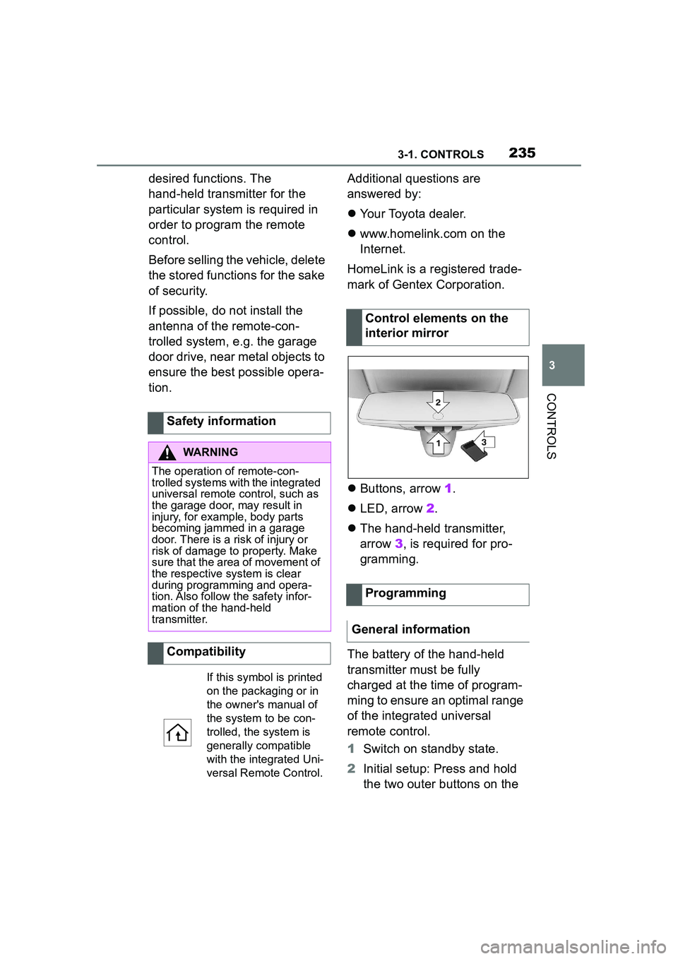
Buttons, arrow 1.
LED, arrow 2.
The hand-held transmitter,
arrow 3, is required for pro-
gramming.
The battery of the hand-held
transmitter must be fully
charged at the time of program-
ming to ensure an optimal range
of the integrated universal
remote control.
1 Switch on standby state.
2 Initial setup: Press and hold
the two outer buttons on the
Safety information
WARNING
The operation of remote-con-
trolled systems with the integrated
universal remote control, such as
the garage door, may result in
injury, for example, body parts
becoming jammed in a garage
door. There is a risk of injury or
risk of damage to property. Make
sure that the area of movement of
the respective system is clear
during programming and opera-
tion. Also follow the safety infor-
mation of the hand-held
transmitter.
Compatibility
If this symbol is printed
on the packaging or in
the owner's manual of
the system to be con-
trolled, the system is
generally compatible
with the integrated Uni-
versal Remote Control.
Control elements on the
interior mirror
Programming
General information
Page 236 of 356
2363-1. CONTROLS
interior mirror simultaneously
for approximately 10 seconds
until the LED flashes green
rapidly. This erases all pro-
gramming of the buttons on
the interior mirror.
3 Press the interior mirror but-
ton to be programmed. The
LED on the interior mirror will
slowly begin flashing orange.
4 Hold the hand-held transmit-
ter for the system to be used
approx. 1 to 12 in/2.5 to 30
cm away from the buttons on
the interior mirror. The
required distance depends
on the hand-held transmitter.
5 Press and hold the button of
the desired function on the
hand-held transmitter.
Canada: if programming with the
hand-held transmitter was inter-
rupted, hold down the interior mirror
button and repeatedly press and
release the hand-held transmitter
button for 2 seconds.
6
The LED lights up green: pro-
gramming completed.
Release the button.
The LED flashes fast: pro-
gramming is not complete.
Press the button on the interior mir-
ror for 2 seconds and release. Per-
form this procedure three times to
complete the programming proce-
dure.
If the integrated universal remote
control remains nonoperational,
continue with the special features for change code wireless systems.
LED does not flash green
after 60 seconds: program-
ming not completed.
Repeat steps 3 to 6.
To program other functions on
other buttons, repeat steps 3 to
5.
If you are unable to operate the
remote-controlled system after
repeated programming, please
check if the system to be con-
trolled features a rolling code
radio system.
Refer to the owner's manual for
the system.
For systems with a rolling code
radio system, the integrated
Universal Remote Control and
the system also have to be syn-
chronized.
Please read the owner's manual
to find out how to synchronize
the system.
Synchronizing is easier with the
aid of a second person.
Synchronizing the universal
remote control with the system:
1 Park the vehicle within range
of the remote-controlled sys-
tem.
2 Program the relevant button
on the interior mirror as
described.
Special feature of the rolling
code wireless system
Page 237 of 356
2373-1. CONTROLS
3
CONTROLS
3Locate and press the syn-
chronizing button on the sys-
tem being programmed, e.g.
at the garage gate. You have
approx. 30 seconds for the
next step.
4 Hold down the programmed
button on the interior mirror
for approximately 3 seconds
and then release it. If neces-
sary, repeat this step up to
three times in order to finish
synchronization. Once syn-
chronization is complete, the
programmed function will be
carried out.
1 Switch on standby state.
2 Press and hold the interior
mirror button to be pro-
grammed.
3 As soon as the LED on the
interior mirror flashes orange
after approx. 20 seconds,
release the button.
4 Hold the hand-held transmit-
ter for the system to be used
approx. 1 to 12 in/2.5 to 30
cm away from the buttons on
the interior mirror. The
required distance depends
on the hand-held transmitter.
5 Press and hold the button of
the desired function on the
hand-held transmitter.
Canada: if programming with the hand-held transmitter was inter-
rupted, hold down the interior mirror
button and repeatedly press and
release the hand-held transmitter
button for 2 seconds.
6
The LED can light up in dif-
ferent ways.
The LED lights up green: the
programming procedure is
completed.
Release the button.
The LED flashes fast: the
hand-held transmitter was
detected but programming is
not complete.
Press the button on the interior mir-
ror for 2 seconds and release. Per-
form this procedure three times to
complete the programming proce-
dure.
If the universal remote control
remains nonoperational, continue
with the special features for change
code wireless systems.
LED does not flash green
after 60 seconds: program-
ming not completed.
Repeat steps 3 to 6.
If the programming procedure is
not completed, the previous pro-
gramming will remain
unchanged.
Reprogramming individ-
ual buttons
Page 238 of 356
2383-1. CONTROLS
The system, such as the garage
door, can be operated using the
button on the interior mirror
while the drive-ready or standby
state is switched on. To do this,
hold down the button within
receiving range of the system
until the function is activated.
The interior mirror LED stays lit
while the wireless signal is being
transmitted.
All stored functions will be
deleted. The functions cannot
be deleted individually.
Press and hold the two outer
buttons on the interior mirror
simultaneously for approxi-
mately 10 seconds until the LED
on the interior mirror flashes
green rapidly.Fold the sun visor down or up.
A vanity mirror is located in the
sun visor behind a cover. When
the cover is opened, the mirror
lighting switches on.
The lighter socket can be used
as a socket for electrical equip-
ment when standby and
drive-ready state are switched
on.
The total load of all sockets
must not exceed 140 watts at 12
volts.
Do not damage the socket by
using non-compatible connec-
tors.
Operation
WARNING
The operation of remote-con-
trolled systems with the integrated
universal remote control, such as
the garage door, may result in
injury, for example, body parts
becoming jammed in a garage
door. There is a risk of injury or
risk of damage to property. Make
sure that the area of movement of
the respective system is clear
during programming and opera-
tion. Also follow the safety infor-
mation of the hand-held
transmitter.
Deleting stored functions
Sun visor
Glare shield
Vanity mirror
Sockets
Concept
General information
Page 311 of 356

3115-1. MOBILITY
5
MOBILITY
F1, F3, F39
F36, F61, F62, F67, F68,
F71
F4
F67, F68
SymbolMeaning
VSC Vehicle Stability
Control System
Parking brake
Air conditioning
Blower motor, Interior
ventilation
Rear window heating
Seat heating
Seat setting
Crash-security module
Switching center column,
Light switch element,
steering Operating panel
Audio
HiFi amplifier, Video mod-
ule TV
Rear-view mirror
Overhead function cen-
ter, Exterior door handle
electronics
Instrument cluster
Additional battery: Dual
Accumulator System
(DSS)
Fuel pump control elec-
tronics, Natural Vacuum
Leak Detection, Gas gen-
erator for battery safety
terminal, Remote control
receiver
Electric window opener
Heating and air-condi-
tioning system
Vehicle's diagnostic port
(interface)
Interior lights in the boot
Vertical Dynamic platform
Vertical Dynamic platform
Vertical Dynamic platform
Mono Camera (Kafas)
Head Unit
Active Sound Design
SymbolMeaning
Page 312 of 356

3125-1. MOBILITY
USB Hub
Body Domain Controller
Controller (Toyota Supra
Command)
Electric fan (air cooler),
Controlled differential
lock
12 V socket, Cigarette
lighter
Interior lights in the boot
Door lock, Exterior door
handle electronics,
Telematic Communica-
tion Box
Electronic gear box con-
trol
Telematic Communica-
tion Box, Exterior door
handle electronics
Electric fan, Rear Power
distributor
Engine control
Switching center column,
Light switch element,
Body Domain Controller
Control panels centre
console, Interior light in
the glove box, Interior
light, Interior light in the
sunvisor, Exterior mirror,
Selector lever
SymbolMeaning
Telematic Communica-
tion Box, Exterior door
handle electronics pas-
senger side
Switcher block driver's
door, Exterior mirror
SymbolMeaning