2022 TOYOTA COROLLA CROSS mirror
[x] Cancel search: mirrorPage 182 of 612
1824-3. Operating the lights and wipers
switch between the high and low
beams.
• When driving in inclement weather
(heavy rain, snow, fog, sand-
storms, etc.)
• When the windshield is obscured
by fog, mist, ice, dirt, etc.
• When the windshield is cracked or damaged
• When the camera sensor is deformed or dirty
• When the temperature of the cam-
era sensor is extremely high
• When the surrounding brightness level is equal to that of headlights,
tail lights or fog lights
• When headlights or tail lights of vehicles ahead are turned off,
dirty, changing color, or not aimed
properly
• When the vehicle is hit by water,
snow, dust, etc. from a preceding
vehicle
• When driving through an area of
intermittently changing brightness
and darkness
• When frequently and repeatedly
driving ascending/descending
roads, or roads with rough, bumpy
or uneven surfaces (such as
stone-paved roads, gravel roads,
etc.)
• When frequently and repeatedly
taking curves or driving on a wind-
ing road
• When there is a highly reflective
object ahead of the vehicle, such
as a sign or mirror
• When the back of a preceding
vehicle is highly reflective, such as
a container on a truck
• When the vehicle’s headlights are
damaged or dirty, or are not aimed
properly
• When the vehicle is listing or titling
due to a flat tire, a trailer being
towed, etc.
• When the headlights are changed between the high beams and low
beams repeatedly in an abnormal
manner
• When the driver believes that the
high beams may be flashing or
dazzling pedestrians or other driv- ers
■Temporarily lowering sensor
sensitivity
The sensitivity of the sensor can be
temporarily lowered.
1 Turn the engine switch off while
the following conditions are met.
●The headlight switch is in or
(if equipped).
●The headlight switch lever is in the
original position.
●Automatic High Beam switch is
on.
2 Turn the engine switch to ON.
3 Within 60 seconds after step 2,
repeat pushing the headlight
switch lever to the high beam
position then pulling it to the orig-
inal position quickly 10 times,
then leave the lever in the origi-
nal position.
4 If the sensitivity is changed, the
Automatic High Beam indicator
is turn on and off 3 times.
■Switching to the high
beams
Push the lever away from you.
The Automatic High Beam indicator
will turn off and the high beam indi-
cator will turn on.
Pull the lever to its original position
to activate the Automatic High
Beam system again.
Turning the high beams
on/off manually
Page 192 of 612

1924-5. Using the driving support systems
WARNING
●Do not attach objects, such as
stickers, transparent stickers,
etc., to the outer side of the
windshield in front of the front
camera (shaded area in the
illustration).From the top of the windshield
to approximately 0.4 in. (1 cm)
below the bottom of the front
camera
Approximately 7.9 in. (20 cm)
(Approximately 4.0 in. [10 cm]
to the right and left from the
center of the front camera)
●If the part of the windshield in
front of the front camera is
fogged up or covered with con-
densation or ice, use the wind-
shield defogger to remove the
fog, condensation or ice.
(
P.411, 419)
●If water droplets cannot be
properly removed from the area
of the windshield in front of the
front camera by the windshield
wipers, replace the wiper insert
or wiper blade.
●Do not attach window tint to the
windshield.
●Replace the windshield if it is
damaged or cracked.
After replacing the windshield,
the front camera must be recali-
brated. Contact your Toyota
dealer for details.
●Do not allow liquids to contact
the front camera.
●Do not allow bright lights to
shine into the front camera.
●Do not dirty or damage the front
camera.
When cleaning the inside of the
windshield, do not allow glass
cleaner to contact the lens of
the front camera. Also, do not
touch the lens.
If the lens is dirty or damaged,
contact your Toyota dealer.
●Do not subject the front camera
to a strong impact.
●Do not change the installation
position or direction of the front
camera or remove it.
●Do not disassemble the front
camera.
●Do not modify any components
of the vehicle around the front
camera (inside rear view mirror,
etc.) or ceiling.
●Do not attach any accessories
to the hood, front grille or front
bumper that may obstruct the
front camera. Co ntact your Toy-
ota dealer for details.
●If a surfboard or other long
object is to be mounted on the
roof, make sure that it will not
obstruct the front camera.
●Do not modify the headlights or
other lights.
Page 233 of 612

2334-5. Using the driving support systems
4
Driving
*: If equipped
Meter control switches
Turning the Blind Spot Monitor
on/off.
Outside rear view mirror indi-
cators
When a vehicle is detected in a
blind spot of the outside rear view
mirrors or approaching rapidly from
behind into a blind spot, the outside
rear view mirror indicator on the
detected side will illuminate. If the
turn signal lever is operated toward
the detected side, the outside rear
view mirror indicator flashes.
BSM OFF indicator
Illuminates when the Blind Spot
Monitor is disabled
■Outside rear view mirror indica-
tor visibility
In strong sunlight, the outside rear
view mirror indicator may be difficult
to see.
■When “Blind Spot Monitor
Unavailable” is shown on the
multi-information display
Ice, snow, mud, etc., may be
attached to the rear bumper around
the sensors. ( P.234) The system
should return to normal operation
after removing the ice, snow, mud,
etc. from the rear bumper. Addition-
ally, the sensors may not operate
BSM (Blind Spot Moni-
tor)*
The Blind Spot Monitor is a
system that uses rear side
radar sensors installed on
the inner side of the rear
bumper on the left and right
side to assist the driver in
confirming safety when
changing lanes.
WARNING
■Cautions regarding the use of
the system
The driver is solely responsible for
safe driving. A lways drive safely,
taking care to observe your sur-
roundings.
The Blind Spot Monitor is a sup-
plementary function which alerts
the driver that a vehicle is in a
blind spot of the outside rear view
mirrors or is approaching rapidly
from behind into a blind spot. Do
not overly rely on the Blind Spot
Monitor. As the function cannot
judge if it is safe to change lanes,
over reliance could lead to an
accident resulting in death or seri-
ous injury.
As the system may not function
correctly under certain condi-
tions, the driver’s own visual con-
firmation of safety is necessary.
System components
Page 235 of 612

2354-5. Using the driving support systems
4
Driving
Use the meter control switches
to turn on/off the function.
1Press or to select .
2 Press or to select
and then press .
■Vehicles that can be detected by the Blind Spot Monitor
The Blind Spot Monitor uses rear si de radar sensors to detect the fol-
lowing vehicles traveling in adjacent lanes and advises the driver of
the presence of such vehicles via the indicators on the outside rear
view mirrors.
Vehicles that are traveling in areas that are not visible using the
outside rear view mirrors (the blind spots)
Vehicles that are approaching r apidly from behind in areas that
are not visible using the outside rear view mirrors (the blind spots)
■The Blind Spot Monitor detection areas
The areas that vehicles can be detected in are outlined below.
WARNING
●Do not disassemble the sensor.
●Do not modify the sensor or sur-
rounding area on the rear
bumper.
●If a sensor or the rear bumper
needs to be removed/installed
or replaced, contact your Toyota
dealer.
●Do not paint the rear bumper
any color other than an official
Toyota color.
Turning the Blind Spot
Monitor on/off
Blind Spot Monitor operation
Page 236 of 612
2364-5. Using the driving support systems
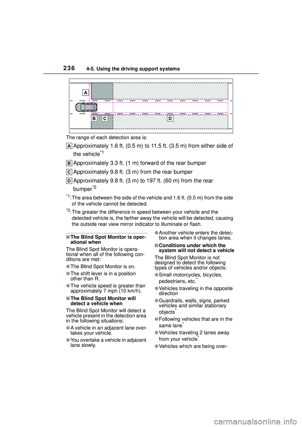
The range of each detection area is:
Approximately 1.6 ft. (0.5 m) to 11.5 ft. (3.5 m) from either side of
the vehicle
*1
Approximately 3.3 ft. (1 m) forward of the rear bumper
Approximately 9.8 ft. (3 m) from the rear bumper
Approximately 9.8 ft. (3 m) to 197 ft. (60 m) from the rear
bumper
*2
*1: The area between the side of the vehicle and 1.6 ft. (0.5 m) from the side
of the vehicle cannot be detected.
*2: The greater the difference in speed between your vehicle and the detected vehicle is, the fa rther away the vehicle will be detected, causing
the outside rear view mirror indicator to illuminate or flash.
■The Blind Spot Monitor is oper-
ational when
The Blind Spot Monitor is opera-
tional when all of the following con-
ditions are met:
●The Blind Spot Monitor is on.
●The shift lever is in a position
other than R.
●The vehicle speed is greater than
approximately 7 mph (10 km/h).
■The Blind Spot Monitor will
detect a vehicle when
The Blind Spot Monitor will detect a
vehicle present in the detection area
in the following situations:
●A vehicle in an adjacent lane over-
takes your vehicle.
●You overtake a vehicle in adjacent
lane slowly.
●Another vehicle enters the detec-
tion area when it changes lanes.
■Conditions under which the
system will not detect a vehicle
The Blind Spot Monitor is not
designed to detect the following
types of vehicles and/or objects:
●Small motorcycles, bicycles,
pedestrians, etc.*
●Vehicles traveling in the opposite
direction
●Guardrails, walls, signs, parked
vehicles and similar stationary
objects
*
●Following vehicles that are in the
same lane*
●Vehicles traveling 2 lanes away
from your vehicle*
●Vehicles which are being over-
Page 238 of 612

2384-5. Using the driving support systems
*: If equipped
Meter control switches
Turning the RCTA function on/off.
When the RCTA function is dis-
abled, the RCTA OFF indicator illu-
minates.
Outside rear view mirror indi-
cators
When a vehicle approaching from
the right or left at the rear of the
vehicle is detected, both outside
rear view mirror indicators will flash.
Audio system display
If a vehicle approaching from the
right or left at the rear of the vehicle
is detected, the RCTA icon
( P.239) for the detected side will
be displayed on the audio system
display. This illustration shows an
example of a vehicle approaching
from both sides of the vehicle.
RCTA buzzer
If a vehicle approaching from the
right or left at the rear of the vehicle
is detected, a buzzer will sound.
The buzzer also sounds for approx-
imately 1 second immediately after
the RCTA function is turned on.
Use the meter control switches
to enable/disable the RCTA
function. ( P.91)
1 Press or to select .
2 Press or to select
“RCTA” and then press .
When the RCTA function is dis-
abled, the RCTA OFF indicator
RCTA (Rear Cross Traf-
fic Aler t)*
The RCTA function uses the
BSM rear side radar sensors
installed behind the rear
bumper. This function is
intended to assist the driver
in checking areas that are
not easily visible when
backing up.
WARNING
■Cautions regarding the use of
the system
There is a limit to the degree of
recognition accuracy and control
performance that this system can
provide, do not overly rely on this
system. The driver is always
responsible for paying attention to
the vehicle’s surroundings and
driving safely. ( P.233)
■To ensure the system can
operate properly
P. 2 3 4
System components
Turning the RCTA func-
tion on/off
Page 239 of 612

2394-5. Using the driving support systems
4
Driving
( P.78) illuminates. (Each time the
engine switch is turned off then
changed to ON, the RCTA function
will be enabled automatically.)
■Outside rear view mirror indica-
tor visibility
In strong sunlight, the outside rear
view mirror indicator may be difficult
to see.
■Hearing the RCTA buzzer
The RCTA buzzer may be difficult to
hear over loud noises, such as if the
audio system volume is high.
■When “Rear Cross Traffic Alert
Unavailable” is shown on the
multi-information display
Water, snow, mud, etc., may be
attached to the rear bumper around
the sensors. ( P.234) Removing
the water, snow, mud, etc., from the
attached to the rear bumper around
the sensors to normal.
Additionally, the function may not
function normally when used in
extremely hot or cold environments.
■Rear side radar sensors
P.234
■Operation of the RCTA function
The RCTA function uses rear side ra dar sensors to detect vehicles
approaching from the right or left at the rear of the vehicle and alerts
the driver of the presence of such vehicles by flashing the outside
rear view mirror indicators and sounding a buzzer.
Approaching vehicles
Detection areas of approaching vehicles
■RCTA icon display
When a vehicle approaching
from the right or left at the rear
of the vehicle is detected, the
following will be displayed on
the audio system display.
This illustration shows an exam-
ple of a vehicle approaching from both sides of the vehicle.
RCTA function
Page 250 of 612

2504-5. Using the driving support systems
WARNING
■When using the rear view
monitor system
The rear view monitor system is a
supplemental device intended to
assist the driver when backing up.
When backing up, be sure to visu-
ally check all around the vehicle
both directly and using the mirrors
before proceeding. Observe the
following precautions to avoid an
accident that could result in death
or serious injuries.
●Never depend on the rear view
monitor system entirely when
backing up. The image and the
position of the guide lines dis-
played on the screen may differ
from the actual state. Use cau-
tion, just as you would when
backing up any vehicle.
●Be sure to back up slowly,
depressing the brake pedal to
control vehicle speed.
●The instructions given are only
guide lines. When and how
much to turn the steering wheel
will vary according to traffic con-
ditions, road surface condi-
tions, vehicle condition, etc.
when parking. It is necessary to
be fully aware of this before
using the rear view monitor sys-
tem.
●When parking, be sure to check
that the parking space will
accommodate your vehicle
before maneuvering into it.
●Do not use the rear view moni-
tor system in the following
cases:
• On icy or slick road surfaces, or in snow
• When using tire chains or emer- gency tires
• When the luggage compartment is not closed completely
• On roads that are not flat or straight, such as curves or
slopes
●In low temperatures, the screen
may darken or the image may
become faint. The image could
distort when the vehicle is mov-
ing, or you may become unable
to see the image on the screen.
Be sure to visually check all
around the vehicle both directly
and using the mirrors before
proceeding.
●If the tire sizes are changed, the
position of the fixed guide lines
displayed on the screen may
change.
●The camera uses a special lens.
The distances between objects
and pedestrians that appear in
the image displayed on the
screen will differ from the actual
distances. ( P.245)
NOTICE
■How to use the camera
●The rear view monitor system
may not operate properly in the
following cases.
• If the back of the vehicle is hit, the position and mounting angle
of the camera may change.
• As the camera has a water proof construction, do not
detach, disassemble or modify
it. This may cause incorrect
operation.